Publicidad
Enlaces rápidos
Installation Guide
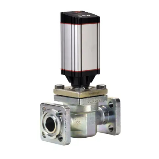
Motor operated valve
ICM 20-65
1
3
4
ICM 20
Åbne
Open
Öffnen
Ouvrir
Abrir
Abrir
6
© Danfoss | DCS (MWA) | 2015.05
ICM 25 - 65
Lukke
Close
Schließen
Fermer
Cerra
Fechar
7
DKRCI.PI.HT0.A5.ML / 520H2713
3
1
2
2
5
ICM 20
Ventilhus / Valve body /
Ventilgehäuse / Corps de vanne /
Cuerpo de válvula
Corpo da válvula
ICM 20
ICM 25
ICM 32
ICM 40
ICM 20
ICM 50
ICM 65
ICM 25 - 65
3
2
ICAD 600A/
ICAD 1200A
NV 12 mm
ICM 25 - 65
ft lbs
Nm
Pie - lbs
pés lbs
40
100
120
120
140
103
150
110
29
74
88
88
1
Publicidad

Resumen de contenidos para Danfoss ICM 20-65
- Página 1 Cuerpo de válvula Ouvrir Fermer pés lbs Corpo da válvula Abrir Cerra ICM 20 Abrir Fechar ICM 25 ICM 32 ICM 40 ICM 20 ICM 50 ICM 65 ICM 25 - 65 © Danfoss | DCS (MWA) | 2015.05 DKRCI.PI.HT0.A5.ML / 520H2713...
- Página 2 ICM sikrer kompatibilitet med regulatorer Manuel drift ca. 45° i den ene eller den anden retning. fra Danfoss, sammen med et udvalg af andre En magnetisk samling kan bruges til at rotere (2) Skub to skruetrækkere ind mellem topdæk- kontrolfunktioner, især PLC-controllere.
- Página 3 The ICM valve is designed for use with the ICAD - (2) Push two screwdrivers in between the top on completion of welding and before the valve actuator from Danfoss. The ICAD actuator on the cover and the valve body. is reassembled.
- Página 4 Das ICM-Ventil muss mit dem Pfeil in um das Funktionsmodul und seine O-Ringe Isolierung Strömungsrichtung eingebaut werden. zu lösen. Das Ventil und sein Stellantrieb müssen Beim Einbau eines ICM darf kein Kältemittel DKRCI.PI.HT0.A5.ML / 520H2713 © Danfoss | DCS (MWA) | 2015.05...
- Página 5 Das alte Modul herausnehmen. Wenden Sie sich im Zweifelsfall bitte an Danfoss. Die O-Ringe am neuen Modul mit einer Zeichnungen dienen nur zur Veranschaulichung, kleinen Menge Kälteöl ölen. nicht für die Dimensionierung oder Konstruktion. Der folgende Text gilt für die UL-gelisteten Danfoss übernimmt keine Verantwortung für...
-
Página 6: Instalación
Utiliser l’outil magnétique (fig. 6) pour - (1) Retirer les 4 boulons, puis appliquer au Danfoss d’origine, y compris pour ce qui est des le visser à fond. Appliquer un peu d’huile module une rotation de 45° environ dans joints et joints toriques. -
Página 7: Montaje
(Amônia) e R744 (CO PLC. Um sinal de controle de um controlador interna elevada. No entanto, o sistema da tubulação Danfoss ou PLC ativará o motor ICAD e através de deve ser concebido para evitar retenções de líquido ICM 25-65: um acoplamento magnético rodará... - Página 8 Uma identificação precisa da válvula é feita através Em casos de dúvida, entre em contato com a Danfoss. da placa ID na tampa superior. Após a soldagem, a superfície externa em volta das conexões do corpo Os desenhos são apenas para ilustração, não se...


