Tabla de contenido
Publicidad
Idiomas disponibles
Idiomas disponibles
Enlaces rápidos
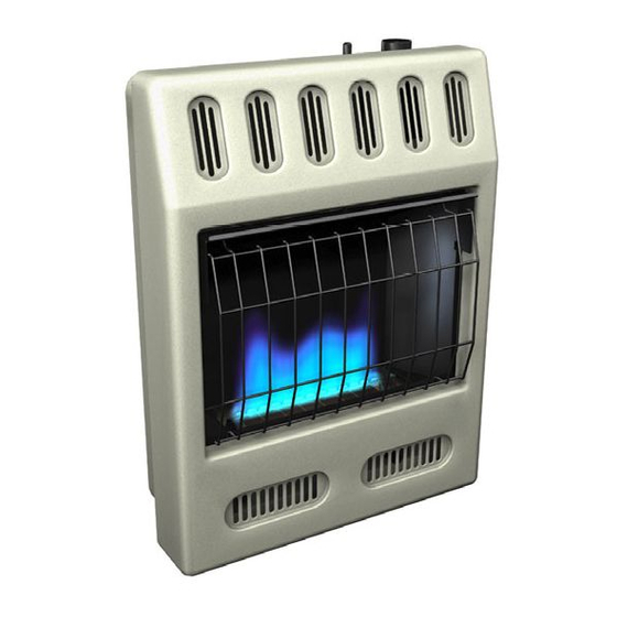
UNVeNTed (VeNT-FRee) BlUe FlaMe Gas HeaTeR
saFeTY INFoRMaTIoN aNd INsTallaTIoN MaNUal
GWN20TB, GWP20TB, GWN30TB, GWP30TB, HdB20NT, HdB20PT,
HdB30NT, HdB30PT, MN20T, MP20T, MN30T, MP30T,
VN20BTB, VP20BTB, VN30BTB, VP30BTB WMN20a, WMP20a
WARNING: If the information in this manual is not
followed exactly, a fire or explosion may result causing
property damage, personal injury or loss of life.
— Do not store or use gasoline or other flammable
vapors and liquids in the vicinity of this or any other
appliance.
— WHAT TO DO IF YOU SMELL GAS
• Do not try to light any appliance.
• Do not touch any electrical switch; do not use any
phone in your building.
• Immediately call your gas supplier from a neighbor's
phone. Follow the gas supplier's instructions.
• If you cannot reach your gas supplier, call the fire
department.
— Installation and service must be performed by a quali-
fied installer, service agency or the gas supplier.
INSTALLER: Leave this manual with the appliance.
CONSUMER: Retain this manual for future reference.
For more information, visit www.desatech.com
Models
Publicidad
Capítulos
Tabla de contenido
Solución de problemas

Manuales relacionados para Desa GWN20TB


Resumen de contenidos para Desa GWN20TB
- Página 1 UNVeNTed (VeNT-FRee) BlUe FlaMe Gas HeaTeR saFeTY INFoRMaTIoN aNd INsTallaTIoN MaNUal Models GWN20TB, GWP20TB, GWN30TB, GWP30TB, HdB20NT, HdB20PT, HdB30NT, HdB30PT, MN20T, MP20T, MN30T, MP30T, VN20BTB, VP20BTB, VN30BTB, VP30BTB WMN20a, WMP20a WARNING: If the information in this manual is not followed exactly, a fire or explosion may result causing property damage, personal injury or loss of life.
-
Página 2: Tabla De Contenido
TaBle oF CoNTeNTs Safety ..............2 Troubleshooting ..........19 Local Codes............4 Specifications ............ 23 Unpacking............4 Replacement Parts ..........23 Product Identification ........... 4 Parts ..............24 Product Features ..........4 Accessories ............26 Air For Combustion And Ventilation ..... 5 Service Hints ............. -
Página 3: Safety
saFeTY Continued Natural and Propane/LP Gas: Natural and Keep the appliance area clear propane/LP gases are fuel gases. Fuel gases and free from combustible ma- are odorless. An odor-making agent is added terials, gasoline and other flam- to fuel gases. The odor helps you detect a fuel mable vapors and liquids. -
Página 4: Local Codes
3. Check heater for any shipping damage. If heater is damaged, promptly return to 2. Remove all protective packaging applied dealer where you bought heater or call to heater for shipment. DESA Heating, LLC at 1-866-672-6040. PRodUCT PRodUCT FeaTURes IdeNTIFICaTIoN SAFETY DEvICE... -
Página 5: Air For Combustion And Ventilation
aIR FoR CoMBUsTIoN aNd VeNTIlaTIoN Unusually Tight Construction WARNING: This heater shall The air that leaks around doors and windows not be installed in a room or may provide enough fresh air for combustion space unless the required vol- and ventilation. However, in buildings of un- usually tight construction, you must provide ume of indoor combustion air additional fresh air. - Página 6 aIR FoR CoMBUsTIoN aNd VeNTIlaTIoN Continued DETERMINING FRESH-AIR FLOW 4. Compare the maximum Btu/Hr the space can support with the actual amount of Btu/ FOR HEATER LOCATION Hr used. Determining if You Have a Confined or _______ Btu/Hr (maximum can support) Unconfined Space _______ Btu/Hr (actual amount used) Use this work sheet to determine if you have a...
-
Página 7: Installation
aIR FoR CoMBUsTIoN aNd VeNTIlaTIoN Continued vENTILATION AIR Ventilation Air From Inside Building 12" This fresh air would come from an adjoining unconfined space. When ventilating to an adjoining unconfined space, you must provide Ventilation Grills Into Adjoining Room, two permanent openings: one within 12" of the Ventilation Option 2 Grills into... -
Página 8: Locating Heater
INsTallaTIoN Continued INSTALLATION ITEMS CAUTION: This heater creates Before installing heater, make sure you have warm air currents. These currents the items listed below. move heat to wall surfaces next • for propane/LP gas, external regulator (supplied by installer) to heater. Installing heater next •... - Página 9 INsTallaTIoN Continued Front Panel Screw THERMOSTAT SENSING BULB (Thermostat Models Only) The thermostat sensing bulb has been placed below the heater. 1. Place clamp on thermostat sensing bulb as shown in Figure 5. Clamp is provided in hardware package. 2. Snap clamp into upper mounting hole as shown in Figure 5.
- Página 10 INsTallaTIoN Continued 2. Mark screw locations on wall (see Figure 8). Attaching To Wall Anchor Method For attaching mounting bracket to hollow Note: Only mark last hole on each end of walls (wall areas between studs) or solid walls mounting bracket. Insert mounting screws (concrete or masonry) through these holes only.
- Página 11 INsTallaTIoN Continued Installing Bottom Mounting Screws MOUNTING HEATER TO FLOOR 1. Locate two bottom mounting holes. These WITH OPTIONAL FLOOR KIT holes are near bottom on back panel of Mounting Base Feet to Heater heater (see Figure 12). Note: A 90° elbow is required for mounting this 2.
- Página 12 INsTallaTIoN Continued CONNECTING TO GAS SUPPLY CAUTION: Use only new, black WARNING: This appliance iron or steel pipe. Internally-tinned requires a 3/8" NPT (National copper tubing may be used in Pipe Thread) inlet connection to certain areas. Check your local the pressure regulator.
- Página 13 INsTallaTIoN Continued CHECKING GAS CONNECTIONS IMPORTANT: Hold the pressure regulator with wrench when connecting it to gas pip- WARNING: Test all gas piping ing and/or fittings. Do not over tighten pipe connection to regulator. The regulator body and connections, internal and could be damaged.
- Página 14 INsTallaTIoN Continued Test Pressures Equal To or Less Than Thermostat Gas Valve 1/2 PSIG (3.5 kPa) 1. Close equipment shutoff valve (see Fig- ure 16). 2. Pressurize supply piping system by either opening propane/LP supply tank valve Meter for propane/LP gas or opening main gas valve located on or near gas meter for natural gas or using compressed air.
-
Página 15: Operation
oPeRaTIoN 6. Thermostat Models: Turn control knob FOR YOUR SAFETY READ counterclockwise to the PILOT BEFORE LIGHTING position. Press in control knob for five (5) seconds. WARNING: If you do not fol- Manual Models: Press in and turn control low these instructions exactly, knob counterclockwise to the PILOT a fire or explosion may result... -
Página 16: Blower Operation
oPeRaTIoN Continued Note: The thermostat sensing bulb measures WARNING: Always operate the temperature of air near the heater cabinet. This may not always agree with room tem- manual control heaters at the perature (depending on housing construction, locked positions. Operation installation location, room size, open air tem- between these positions may peratures, etc.). -
Página 17: Inspecting Heater
oPeRaTIoN Continued Extension Cord minutes after unit cycles off or is turned off, Use extension cord if needed. The cord must blower will shut off. Blower will cycle on and off have a three-prong, grounding plug and a in this manner. Note: If you have a heater with three-hole receptacle. -
Página 18: Cleaning And Maintenance
CleaNING aNd MaINTeNaNCe We also recommend that you keep the burner WARNING: Turn off heater tube and pilot assembly clean and free of dust and let cool before cleaning. and dirt. To clean these parts we recommend using compressed air no greater than 30 PSI. Your local computer store, hardware store or CAUTION: You must keep home center may carry compressed air in a... -
Página 19: Troubleshooting
TRoUBlesHooTING WARNING: Turn off and unplug heater and let cool before servicing. Only a qualified service person should service and repair heater. CAUTION: Never use a wire, needle or similar object to clean ODS/pilot. This can damage ODS/pilot unit. Note: All troubleshooting items are listed in order of operation. OBSERvED PROBLEM POSSIBLE CAUSE REMEDY... - Página 20 TRoUBlesHooTING Continued OBSERvED PROBLEM POSSIBLE CAUSE REMEDY ODS/pilot lights but flame 1. Control knob not fully 1. Press in control knob fully goes out when control knob pressed in is released 2. Control knob not pressed in 2. After ODS/pilot lights, keep long enough control knob pressed in 30 seconds...
- Página 21 TRoUBlesHooTING Continued OBSERvED PROBLEM POSSIBLE CAUSE REMEDY Yellow flame during burner 1. Not enough air 1. Check burner for dirt and combustion debris. If found, clean burner (see Cleaning and Maintenance, page 18) 2. Gas regulator defective 2. Replace gas regulator 3.
- Página 22 TRoUBlesHooTING Continued WARNING: If you smell gas • Shut off gas supply. • Do not try to light any appliance. • Do not touch any electrical switch; do not use any phone in your building. • Immediately call your gas supplier from a neighbor’s phone. Fol- low the gas supplier’s instructions.
-
Página 23: Specifications
Parts call DESA Heating, LLC at 1-866-672-6040. Central (see page 27) or call DESA Heating, LLC at 1-866-672-6040 for referral informa- When calling DESA Heating, LLC, have tion. A list of authorized dealers can be found ready: by visiting www.desatech.com. -
Página 24: Parts
PaRTs MODELS GWN20TB, GWP20TB, GWN30TB, GWP30TB HDB20NT, HDB20PT, HDB30NT, HDB30PT, MN20T, MP20T, MN30T, MP30T, VN20BTB, VP20BTB, VN30BTB, VP30BTB, WMN20A, WMP20A 18** 19** *Manual Control Models Only **Thermostat Models Only Battery Install Battery Positive According To Battery This Illustration Negative (Actual ignitor... - Página 25 PaRTs This list contains replaceable parts used in your heater. When ordering parts, follow the instructions listed under Replacement Parts on page 23 of this manual. NO. PART NO. DESCRIPTION QTY. 097159-04 Piezo Ignitor • • • • • • 111435-01 Electronic Ignitor •...
-
Página 26: Accessories
Purchase these accessories from your local dealer. If they can not supply these accessories, either contact your nearest Parts Central or call DESA Heating, LLC at 1-866-672-6040 for information. You can also write to the address listed on the back page of this manual. -
Página 27: Parts Central
PaRTs CeNTRal These Parts Centrals are privately owned businesses. They have agreed to support our customer’s needs by providing original replacement parts and accessories. Those Heater Guys Washer Equipment Co. 255 E. Stowell Street 1715 Main Street Upland, CA 91786 Kansas City, MO 64108 909-928-3011 KS, MO, AR... - Página 28 DESA Heating, LLC 2701 Industrial Drive Bowling Green, KY 42101 www.desatech.com 1-866-672-6040 124002-01 Rev. C 09/08...
- Página 29 CALENTADOR DE GAS DE LLAMA AZUL NO VENTILADO (SIN VENTILAS) INFORMACIÓN DE SEGURIDAD Y MANUAL DE INSTALACIÓN MODELOS GWN20TB, GWP20TB, GWN30TB, GWP30TB, HDB20NT, HDB20PT, HDB30NT, HDB30PT, MN20T, MP20T, MN30T, MP30T, VN20BTB, VP20BTB, VN30BTB, VP30BTB WMN20A, WMP20A ADVERTENCIA: si la información contenida en este manual no se sigue al pie de la letra, se puede producir un incendio o una explosión que podría ocasionar daños a la...
- Página 30 TABLA DE CONTENIDO Seguridad ............2 Solución de problemas ........22 Códigos locales ........... 4 Piezas ..............26 Identificación del producto ........5 Especificaciones ..........28 Desempaque ............5 Consejos para servicio ........28 Características del producto ........ 5 Servicio técnico ..........28 Aire para combustión y ventilación ......
-
Página 31: Seguridad
SEGURIDAD Continuación No coloque ropa ni otros mate- PELIGRO: ¡la intoxicación riales inflamables sobre el apa- con monóxido de carbono puede rato ni cerca del mismo. Nunca resultar en la muerte! coloque ningún objeto sobre el calentador. Intoxicación con monóxido de carbono: los síntomas iniciales de la intoxicación con monóxido de carbono son semejantes a los La superficie del calentador alcan- de la gripe, con dolores de cabeza, mareos... -
Página 32: Códigos Locales
SEGURIDAD Continuación 4. Si percibe olor a gas: 9. Apague el calentador antes de usar puli- • Cierre el suministro de gas, dores de muebles, ceras, limpiadores de • No intente encender ningún aparato, alfombras o productos parecidos. Si se ca- •... -
Página 33: Identificación Del Producto
3. Revise el calentador para ver si hay algún daño debido al transporte. Si el calentador 2. Retire todo el empaque de protección que está dañado, llame a DESA Heating, LLC al se agregó al calentador para su envío. 1-866-672-6040 para obtener piezas de re- puesto antes de devolverlo al distribuidor. -
Página 34: Aire Para Combustión Y Ventilación
AIRE PARA COMBUSTIÓN Y VENTILACIÓN Todos los espacios en las casas se pueden ADVERTENCIA: esta calen- clasificar en una de las tres categorías de tador no se debe instalar en una ventilación siguientes: habitación o espacio a menos 1. Construcción inusualmente sellada que se proporcione el volumen 2. -
Página 35: Determinación Del Flujo De Aire Fresco Para Ubicar El Calentador
AIRE PARA COMBUSTIÓN Y VENTILACIÓN Continuación por kW (50 pies cúbicos por 1,000 BTU/h) de Calentador sin ventilación _________ BTU/h Calentador de agua a gas* _________ BTU/h clasificación de entrada agregada de todos Horno de gas _________ BTU/h los aparatos instalados en ese espacio. Las Calentador de gas con ventilación habitaciones que se comunican directamente _________ BTU/h... -
Página 36: Aire Para Ventilación
AIRE PARA COMBUSTIÓN Y VENTILACIÓN Continuación espacios debajo del piso de la casa. Consulte ADVERTENCIA: si el área en el Código nacional de gas combustible, ANSI la que se va a operar el calenta- Z223.1/NFPA 54, Aire para combustión y ven- dor no cumple los requisitos de tilación, para conocer el tamaño requerido de las rejillas o conductos de ventilación. -
Página 37: Instalación
INSTALACIÓN • Para propano o gas LP, un regulador ex- AVISO: este calentador está terno (proporcionado por el instalador), diseñado para utilizarse como • tubería (consulte los códigos locales), calefacción adicional. Use este • sellador (resistente al propano o gas LP), calentador junto con su sistema •... -
Página 38: Bulbo Sensor De Termostato
INSTALACIÓN Continuación Puede ubicar el calentador en el piso, lejos PRECAUCIóN: si instala el de la pared. Se necesita un estante opcional calentador en la chochera de para montaje en piso. Adquiera el estante una casa para montaje en piso con el distribuidor. Con- sulte Accesorios en la página 29, si no viene • el piloto y el quemador del calen- incluida una base con su calentador. -
Página 39: Instalación Del Calentador En La Pared
INSTALACIÓN Continuación INSTALACIóN DEL CALENTADOR Fijación a anclajes de pared: este método le permite fijar el soporte de montaje en pa- EN LA PARED redes huecas (las áreas de la pared que se Soporte de montaje encuentran entre los maderos) o en paredes Localice el soporte de montaje en la caja del sólidas (de concreto o mampostería). - Página 40 INSTALACIÓN Continuación Nota: marque únicamente el último orificio 6. Inserte los tornillos de montaje en el de cada extremo del soporte de montaje. soporte y en los anclajes de pared. Inserte los tornillos de montaje en estos 7. Apriete los tornillos hasta que el soporte orificios solamente.
-
Página 41: Montaje Del Calentador En El Piso (Opcional)
INSTALACIÓN Continuación 5. Vuelva a colocar el calentador en el so- una llave para tuberías cuando conecte porte de montaje. el codo. No apriete demasiado el codo al regulador. El cuerpo del regulador se 6. Coloque los separadores entre los orifi- puede dañar. -
Página 42: Conexión Al Suministro De Gas
INSTALACIÓN Continuación CONEXIóN AL SUMINISTRO DE GAS PREcAUciÓN: utilice única- mente tubería nueva, de hierro ADVERTENCIA: este aparato negro o de acero. En ciertas requiere una conexión de entra- áreas, se puede usar tubería de da tipo NPT (rosca de tubería cobre galvanizada internamen- nacional) de 3/8" al regulador te. -
Página 43: Revisión De Las Conexiones De Gas
INSTALACIÓN Continuación Instale la trampa de sedimentos en la línea de calentador. Si la trampa de sedimentos no se suministro como se muestra en la figura 15. instala o se instala incorrectamente, el calen- Sitúe la trampa de sedimentos de manera que tador podría no funcionar correctamente. -
Página 44: Comprobación De La Presión De Las Conexiones De Gas Del Calentador
INSTALACIÓN Continuación 2. Coloque una tapa en el extremo abierto COMPROBACIóN DE LA PRESIóN DE LAS del tubo de gas donde estaba conectada CONEXIONES DE GAS DEL CALENTADOR la válvula de cierre del equipo. 1. Abra la válvula de cierre del equipo (con- sulte la figura 16). -
Página 45: Funcionamiento
FUNCIONAMIENTO POR SU SEGURIDAD, LEA INSTRUCCIONES DE ENCENDIDO ESTO ANTES DE ENCENDER 1. ¡ALTO! Lea la información seguridad EL CALENTADOR antes mencionada 2. Asegúrese de que la válvula de cierre del ADVERTENCIA: si no sigue equipo esté totalmente abierta. estas instrucciones al pie de la 3. -
Página 46: Cómo Cerrar El Suministro De Gas Al Aparato
FUNCIONAMIENTO Continuación Nota: es posible que ésta sea la primera vez PRECAUCIóN: no intente que hace funcionar el calentador después de ajustar los niveles de calefac- conectarlo al suministro de gas. Si es así, ción por medio de la válvula de es posible que deba presionar la perilla de control durante 30 segundos o más. -
Página 47: Procedimiento Para Encendido Manual
FUNCIONAMIENTO Continuación Nota: el bulbo sensor de termostato mide la PRECAUCIóN: No conecte temperatura del aire cercano al gabinete del el cable de alimentación en el calentador. Es posible que ésta no siempre tomacorriente sino hasta que la concuerde con la temperatura de la habita- ción (dependiendo de la construcción de la instalación esté... -
Página 48: Inspección Del Calentador
INSPECCIÓN DEL CALENTADOR PATRóN DE LA LLAMA DEL Revise frecuentemente los patrones de la llama del piloto y de la llama del quemador. CALENTADOR PATRóN DE LA LLAMA DEL PILOTO ADVERTENCIA: si se presen- La figura 24 muestra un patrón correcto de ta un color amarillo en las pun- la llama del piloto. -
Página 49: Limpieza Y Mantenimiento
LIMPIEZA Y MANTENIMIENTO También se recomienda que mantenga el ADVERTENCIA: apague el conjunto de tubo y piloto del calentador calentador y deje que se enfríe limpio y libre de polvo y suciedad. Para lim- antes de limpiarlo. piar estas piezas, se recomienda usar aire comprimido a una presión no mayor de 30 PSI. -
Página 50: Solución De Problemas
SOLUCIÓN DE PROBLEMAS ADVERTENCIA: apague y desconecte el calentador y deje que se enfríe antes de darle servicio. Sólo una persona de servicio capacitada debe reparar el calentador o darle servicio. PRECAUCIóN: nunca utilice un alambre, aguja u objetos parecidos para limpiar el piloto/ODS. - Página 51 SOLUCIÓN DE PROBLEMAS Continuación PROBLEMA OBSERVADO CAUSA POSIBLE REMEDIO El piloto con ODS se encien- 1. La perilla de control no está 1. Presione totalmente la pe- de pero la llama se extingue presionada completamente rilla de control cuando se suelta la perilla 2.
- Página 52 SOLUCIÓN DE PROBLEMAS Continuación PROBLEMA OBSERVADO CAUSA POSIBLE REMEDIO Llamas amarillas durante la 1. No hay suficiente aire 1. Revise el quemador en bus- combustión en el quemador ca de polvo y residuos. Si los hay, limpie el quemador (consulte Limpieza y mante- nimiento, en la página 21) 2.
- Página 53 SOLUCIÓN DE PROBLEMAS Continuación ADVERTENCIA: si percibe olor a gas, • cierre el suministro de gas. • No intente encender ningún aparato. • No toque ningún interruptor eléctrico; no use ningún teléfono en el edificio. • Llame inmediatamente a su proveedor de gas desde el teléfono de algún vecino. Siga las instrucciones del proveedor de gas. • Si no puede localizar al proveedor de gas, llame al departamento de bomberos. IMPORTANTE: si hace funcionar el calentador donde existen impurezas en el aire se pueden producir olores. Los productos de limpieza, pintura, solventes de pintura, humo de cigarro, cementos y pegamentos, alfombras o textiles nuevos, etc., producen gases.
-
Página 54: Piezas
PIEZAS ModELoS GWN20TB, GWP20TB, GWN30TB, GWP30TB HdB20NT, HdB20PT, HdB30NT, HdB30PT, MN20T, MP20T, MN30T, MP30T, VN20BTB, VP20BTB, VN30BTB, VP30BTB, WMN20A, WMP20A 18** 19** *Sólo para modelos de termostato *Manual Control Models Only **Sólo para modelos de **Thermostat Models Only manuales Battery Instale la batería Batería Positive como se muestra AAA polo Battery en esta figura negativo Negative... -
Página 55: Piezas Disponibles - (No Ilustradas)
PIEZAS Esta lista contiene las piezas reemplazables utilizadas en el calentador. Al hacer un pedido de piezas, siga las instrucciones enumeradas en Piezas de repuesto en la página 29 de este manual. N° DE N° PARTE DESCRIPCIóN CANT 097159-04 Encendido piezoeléctrico •... -
Página 56: Especificaciones
• El quemador tendrá un retraso durante el y serie de su calentador. encendido. También puede visitar el sitio web de DESA • El calentador no producirá el calor especi- Heating, LLC en www.desatech.com. ficado. -
Página 57: Piezas De Repuesto
Adquiera estos accesorios con su distribuidor local. Si no pueden proporcionarle estos accesorios, comuníquese con la Central de piezas más cercana o llame a DESA Hea- ting, LLC al 1-866-672-6040 para obtener información. También puede escribir a la dirección que aparece en la última página de este manual. -
Página 58: Central De Piezas
CENTRAL DE PIEZAS Estas Centrales de piezas son empresas privadas. Han aceptado dar asistencia a las nece- sidades de nuestros clientes ofreciendo piezas de repuesto y accesorios originales. Those Heater Guys Washer Equipment Co. 255 E. Stowell Street 1715 Main Street Upland, CA 91786, EE.UU. - Página 59 NOTAS _____________________________________________________ ______________________________________________________ ______________________________________________________ ______________________________________________________ ______________________________________________________ ______________________________________________________ ______________________________________________________ ______________________________________________________ ______________________________________________________ ______________________________________________________ ______________________________________________________ ______________________________________________________ ______________________________________________________ _____________________________________________________ ______________________________________________________ ______________________________________________________ ______________________________________________________ ______________________________________________________ ______________________________________________________ ______________________________________________________ ______________________________________________________ ______________________________________________________ ______________________________________________________ ______________________________________________________ ______________________________________________________ ______________________________________________________ _____________________________________________________ ______________________________________________________ ______________________________________________________ ______________________________________________________ ______________________________________________________ ______________________________________________________ ______________________________________________________ ______________________________________________________ ______________________________________________________ 124002-01C www.desatech.com...
- Página 60 DESA Heating, LLC 2701 Industrial Drive Bowling Green, KY 42101 www.desatech.com 1-866-672-6040 124002-01 124002 01 Rev. C NOT A UPC 09/08...