Tabla de contenido
Publicidad
Idiomas disponibles
Idiomas disponibles
Enlaces rápidos
Bedieningshandleiding en
installatieinstructies
Operation manual and
installation instructions
Bedienungshandbuch und
Einbauanleitung
Manuel d'utilisation et
instructions d'installation
Manual de manejo y
instrucciones de instalación
Manuale per l'uso e
istruzioni per l'installazione
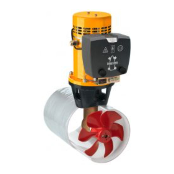
80 kgf
ø 185 mm
C o p y r i g h t © 2 0 0 1 Ve t u s d e n O u d e n n . v. S c h i e d a m H o l l a n d
Publicidad
Tabla de contenido

Manuales relacionados para Vetus 80 kgf


Resumen de contenidos para Vetus 80 kgf
- Página 1 Manuale per l’uso e istruzioni per l’installazione 80 kgf ø 185 mm C o p y r i g h t © 2 0 0 1 Ve t u s d e n O u d e n n . v. S c h i e d a m H o l l a n d...
-
Página 2: Tabla De Contenido
Inhoud Contents Inleiding Introduction Veiligheid Safety Gebruik Installatieinstructies Installation instructions Installatie aanbevelingen Installation recommendations Inbouw Installation Stroomverzorging The power supply Elektrische installatie Electrical installation Onderhoud Maintenance Storingen Trouble shooting Technische gegevens Technical data Inbouwvoorbeelden Installation examples Elektrisch schema Wiring diagram Hoofdafmetingen Principal dimensions Inhalt... -
Página 3: Inleiding
VOORZICHTIG! Indien 2 bedieningspanelen zijn geïnstalleerd; bedien de Boegschroef ‘80 kgf’ - 12 V : 3 min. bij 580 A boegschroef dan nooit gelijktijdig vanaf beide pane- ‘80 kgf’ - 24 V : 4 min. bij 280 A len. -
Página 4: Installatieinstructies
De electromotor dient steeds boven het maximale niveau voor grotere schepen. Bij van het bilge-water ( ) te worden opgesteld. deze opstelling kunnen, afhankelijk weers- omstandigheden e.d., één of beide boegschroeven worden gebruikt. 2.0525 Bedieningshandleiding en installatieinstructies Boegschroef 80 kgf, ø 185 mm... -
Página 5: Overgang Van Tunnelbuis Naar Scheepsromp
Kies de lengte ‘L’ voor een schelp tussen 1 x D en 3 x D. Een schelp dient zodanig in de scheepsromp te zijn opgeno- men dat de hartlijn van de schelp samenvalt met de te ver- wachten vorm van de boeggolf. 2.0525 Bedieningshandleiding en installatieinstructies Boegschroef 80 kgf, ø 185 mm... -
Página 6: Inbouw
Monteer de tunnelbuis. Breng de gaten aan in de tun- nelbuis en werk deze braam- vrij af. D = 30 mm d = 9,0 mm 2.0525 Bedieningshandleiding en installatieinstructies Boegschroef 80 kgf, ø 185 mm... -
Página 7: Montage Staartstuk En Tussenflens
Draai ter controle met de hand de schroef rond, deze moet gemakkelijk zijn rond te draaien, waarbij de electro- motoras wordt meegeno- men. 2.0525 Bedieningshandleiding en installatieinstructies Boegschroef 80 kgf, ø 185 mm... -
Página 8: Stroomverzorging
355 A ZE 355 80 kgf 24 V 2 x ca. 100 Ah - 12 V 0 - 19 m 50 mm 160 A ZE 160 ) In serie geschakeld. 2.0525 Bedieningshandleiding en installatieinstructies Boegschroef 80 kgf, ø 185 mm... -
Página 9: Elektrische Installatie
Electrische installatie op het eerste paneel worden aangesloten. Controleer of de spanning, vermeld op het typeplaatje van de Raadpleeg Vetus den Ouden N.V. indien, in plaats van een motor, overeenkomt met de boordspanning. Vetus bedieningspaneel, twee aparte schakelaars worden toe- Plaats de accu of accu’s zo dicht mogelijk bij de boegschroef;... -
Página 10: Onderhoud
BP238 Voor accu-onderhoud dienen de instructies van de acculever- Raadpleeg Vetus voor andere motortypen dan bovengenoemd. ancier te worden geraadpleegd. VETUS accu’s zijn onder- houdsvrij. 2.0525 Bedieningshandleiding en installatieinstructies Boegschroef 80 kgf, ø 185 mm... -
Página 11: Storingen
Sluit stuurstroom- en hoodstroomkabels weer aan en zet de hoofdschakelaar aan. Controleer de goede werking van de boegschroef. Overtuig u ervan dat geen obstakels meer in de tunnelbuis aanwezig zijn. 2.0525 Bedieningshandleiding en installatieinstructies Boegschroef 80 kgf, ø 185 mm... -
Página 12: Technische Gegevens
) 3 min. continu of max. 3 min per uur bij 580 A (12 Volt). ) 4 min. continu of max. 4 min per uur bij 280 A (24 Volt). 2.0525 Bedieningshandleiding en installatieinstructies Boegschroef 80 kgf, ø 185 mm... -
Página 13: Introduction
(or vice-versa) in one movement. - When use of the bow propeller is no longer required, again press the ‘ON/OFF’ switch. - Switch off the main switch when leaving the ship. 2.0525 Operation manual and installation instructions Bow thruster 80 kgf, ø 185 mm... -
Página 14: Installation Instructions
We do not advise fitting 2 bow thrusters into one tun- nel; this does not result in doubling the thrust! 2.0525 Operation manual and installation instructions Bow thruster 80 kgf, ø 185 mm... -
Página 15: Connection Of Thrust Tunnel To Ship's Hull
This fairing should be embodied in the ship’s hull in such a way that the centerline of the fairing will correspond with the antici- pated shape of the bow-wave. 2.0525 Operation manual and installation instructions Bow thruster 80 kgf, ø 185 mm... -
Página 16: Installation Of The Thrust Tunnel
Drill the holes through the thrust tunnel and take care D = 30 mm that the holes are free of (1.18”) burrs. d = 9,0 mm (0.35”) 2.0525 Operation manual and installation instructions Bow thruster 80 kgf, ø 185 mm... -
Página 17: Final Assembly
For a first check, turn the pro- peller by hand, it should turn easily, whilst being connect- ed to the output spindle of the electric motor 2.0525 Operation manual and installation instructions Bow thruster 80 kgf, ø 185 mm... -
Página 18: The Power Supply
10% of the volt- age supplied; see the table. A main switch and fuse must be fitted in the ‘plus’ cable. A Vetus battery switch is suitable here. The fuse protects the bow thruster against overvoltage and at the same time protects the vessel’s wiring against short-circuits. -
Página 19: Series/Parallel Switch
Fit the control panel next to the steering position. There must be Never allow the bow thruster to run for longer than 5 at least 50 mm space behind the panel. seconds with the ship out of water. 2.0525 Operation manual and installation instructions Bow thruster 80 kgf, ø 185 mm... -
Página 20: Maintenance
The instructions of the manufacturer should be followed for the maintenance of the batteries. Vetus batteries are maintenance BP238 free. Consult with Vetus for motor types other than those given here. 2.0525 Operation manual and installation instructions Bow thruster 80 kgf, ø 185 mm... -
Página 21: Trouble Shooting
Reconnect the control panel and main cables and switch on the battery main switch. Check that the bow thruster works properly. Check that there are no further objects in the tunnel. 2.0525 Operation manual and installation instructions Bow thruster 80 kgf, ø 185 mm... -
Página 22: Technical Data
) 3 min. continuously or max. 3 min. per hour at 580 A (12 Volt). ) 4 min. continuously or max. 4 min. per hour at 280 A (24 Volt). 2.0525 Operation manual and installation instructions Bow thruster 80 kgf, ø 185 mm... -
Página 23: Einleitung
Wenn Armaturenbretter eingebaut sind, Bugschraube ‘80 kgf’ - 12 V : 3 Min. bei 580 A Bugschraube nie gleichzeitig von beiden Armaturen- ‘80 kgf’ - 24 V : 4 Min. bei 280 A brettern aus bedienen. - Hauptschalter einschalten. ACHTUNG! -
Página 24: Einbauanleitung
Bei horizontaler Aufstellung des Motors ist eine Unterstützung für größere Schiffe. Hierbei absolut erforderlich. Der Elektromotor soll immer oberhalb des kann man, abhängig vom höchstmöglichen Bilgenwasserniveaus ( ) aufgestellt Wetter, eine oder beide werden. Bugschrauben benutzen. 2.0525 Bedienungshandbuch und Einbauanleitung Bugschraube 80 kgf, ø 185 mm... -
Página 25: Übergang Vom Tunnelrohr Zum Schiffsrumpf
Die Länge ‘L’ des Muschels soll zwischen 1 x D und 3 x D sein. Ein Muschel soll auf solcher Art und Weise in den Schiffsrumpf aufgenommen werden, daß die Herzlinie des Muschels mit der zu erwartenden Form der Bugwelle zusammenfällt. 2.0525 Bedienungshandbuch und Einbauanleitung Bugschraube 80 kgf, ø 185 mm... -
Página 26: Einbau
Wichtig: Die Löcher sollen Stichsäge oder eines exact auf der Herzlinie des Schneidbrenners. Tunnels angebracht werden. Löcher Tunnels Tunnelrohr montieren. bohren sorgfältig abgraten. D = 30 mm d = 8,5 mm 2.0525 Bedienungshandbuch und Einbauanleitung Bugschraube 80 kgf, ø 185 mm... -
Página 27: Befestigung Des Unterwasserteils Und Des Zwischenflansches
Das Gewinde der Bolzen mit ‘outbourd gear grease’ einfetten Elektromotor Zwischenflansch montieren. Als erste Probe den Propeller von Hand drehen; das sollte reibungslos geschehen, als zugleich Welle Elektromotors mitgenommen wird. 2.0525 Bedienungshandbuch und Einbauanleitung Bugschraube 80 kgf, ø 185 mm... -
Página 28: Stromversorgung
355 A ZE 355 80 kgf 24 V 2 x ca. 100 Ah - 12 V 0 - 19 m 50 mm 160 A ZE 160 ) In Serie geschaltet. 2.0525 Bedienungshandbuch und Einbauanleitung Bugschraube 80 kgf, ø 185 mm... -
Página 29: Elektrische Installation
Spannung mit der Bordspannung übereinstimmt. Den Akku oder die Akkus so nah wie möglich bei der Ziehen Sie Vetus den Ouden N.V. zu Rate, wenn anstelle eines Bugschraube aufstellen, die Hauptstromkabel können dann Vetus Armaturenbretts zwei einzelne Schalter verwendet kurz sein, und der Spannungsverlust bleibt gering. -
Página 30: Wartung
Achse 16 mm min. einbauen. Akku-Wartung sind Anweisungen Akkulieferanten zu beachten. VETUS Akkus sind wartungsfrei. BP238 Bei anderen Motorentypen als oben angegeben ziehen Sie bitte Vetus zu Rate. 2.0525 Bedienungshandbuch und Einbauanleitung Bugschraube 80 kgf, ø 185 mm... -
Página 31: Störungen
Steuerstrom- und Hauptstromkabel wieder anschließen und den Hauptschalter auf ‘AN’ stellen. Prüfen Sie, ob die Überzeugen Sie sich davon, daß keine Hindernisse mehr im Bugschraube richtig funktioniert. Tunnelrohr vorhanden sind. 2.0525 Bedienungshandbuch und Einbauanleitung Bugschraube 80 kgf, ø 185 mm... -
Página 32: Technische Daten
) 3 Min. Dauer oder max. 3 Min. pro Stunde bei 580 A (12 Volt). ) 4 Min. Dauer oder max. 4 Min. pro Stunde bei 280 A (24 Volt). 2.0525 Bedienungshandbuch und Einbauanleitung Bugschraube 80 kgf, ø 185 mm... -
Página 33: Introduction
Si 2 tableaux de commande sont installés, ne comman- dez jamais l’hélice d’étrave à partir des deux tableaux Hélice d’étrave: ‘80 kgf’ - 12 V : 3 min. à 580 A en même temps. ‘80 kgf’ - 24 V : 4 min. à 280 A - Mettre sous tension l’interrupteur général. -
Página 34: Instructions D'installation
( bateaux). Dans ce type de montage, on utilise une ou deux hélices selon l’état du temps. 2.0525 Manuel d’utilisation et instructions d’installation de l’hélice d’étrave 80 kgf, ø 185 mm... -
Página 35: Adaption De La Tuyère À L'étrave
Cette coquille sera incorporée dans la coque du bateau de telle sorte, que la ligne centrale se confondra avec la forme de la vague de l’étrave prévue. 2.0525 Manuel d’utilisation et instructions d’installation de l’hélice d’étrave 80 kgf, ø 185 mm... -
Página 36: Installation De La Tuyère
Installer la tuyère. Percer les trous dans la tuyère et les ébarber avec soin. D = 30 mm d = 9,0 mm 2.0525 Manuel d’utilisation et instructions d’installation de l’hélice d’étrave 80 kgf, ø 185 mm... -
Página 37: Montage Final
électrique sur la bride intermédiaire. Contrôler, en tournant l’hélice à main, ce doit se faire sans friction, quand l’arbre du moteur électrique est prise. 2.0525 Manuel d’utilisation et instructions d’installation de l’hélice d’étrave 80 kgf, ø 185 mm... -
Página 38: L'alimentation Électrique
80 kgf 24 V 2 x ± 100 Ah - 12 V 0 - 19 m 50 mm 160 A ZE 160 ) Monté en série. 2.0525 Manuel d’utilisation et instructions d’installation de l’hélice d’étrave 80 kgf, ø 185 mm... -
Página 39: Installation Électrique
5 secondes. Monter le panneau de contrôle sur le poste de conduite. L’espace libre derrière le panneau doit être d’au moins 50 mm. 2.0525 Manuel d’utilisation et instructions d’installation de l’hélice d’étrave 80 kgf, ø 185 mm... -
Página 40: Entretien
Les batteries VETUS Adressez-vous à Vetus pour les types de moteur autres que ne nécessitent pas d’entretien. ceux mentionnés ci-dessus. 2.0525 Manuel d’utilisation et instructions d’installation de l’hélice d’étrave 80 kgf, ø 185 mm... -
Página 41: Pannes
Vérifiez le bon fonc- tionnement de l’hélice d’étrave. Vérifiez qu’il n’y a plus d’obstacle dans la tuyère. 2.0525 Manuel d’utilisation et instructions d’installation de l’hélice d’étrave 80 kgf, ø 185 mm... -
Página 42: Renseignements Techniques
) 3 min. en continu ou maximum 3 min. par heure à 580 A (12 Volt). ) 4 min. en continu ou maximum 4 min. par heure à 280 A (24 Volt). 2.0525 Manuel d’utilisation et instructions d’installation de l’hélice d’étrave 80 kgf, ø 185 mm... -
Página 43: Introducción
- Terminado el funcionamiento de la hélice de estrave, pulsar otra vez el interruptor ‘ON/OFF’. - Si ud. va a desembarcar, desconectar el interruptor principal. 2.0525 Manual de manejo y instrucciones de instalación para la hélice de proa 80 kgf, ø 185 mm... -
Página 44: Instrucciones De Instalación
En este caso, dependiendo de las condiciones climato- lógicas, se pueden utilizar una o ambas hélices de proa. 2.0525 Manual de manejo y instrucciones de instalación para la hélice de proa 80 kgf, ø 185 mm... -
Página 45: Acoplamiento Del Conducto De Propulsión Al Casco
Un enmaestrado se incorporará de tal modo en el casco que el eje central del enmaestrado coincida con la forma prevista de la ola de proa. 2.0525 Manual de manejo y instrucciones de instalación para la hélice de proa 80 kgf, ø 185 mm... -
Página 46: Incorporación
Montar el conducto de pro- bar los mismos. pulsión. D = 30 mm d = 9,0 mm 2.0525 Manual de manejo y instrucciones de instalación para la hélice de proa 80 kgf, ø 185 mm... -
Página 47: Instalación De La Parte Posterior Y La Brida Intermedia
Para un primer control, girar con la mano la hélice, que debe girar fricción, haciendo girar al tiempo el eje del electromotor. 2.0525 Manual de manejo y instrucciones de instalación para la hélice de proa 80 kgf, ø 185 mm... -
Página 48: El Suministro De Corriente
2 x aprox. 100 Ah - 12 V 0 - 19 m 50 mm 160 A ZE 160 ) Conectadas en serie. 2.0525 Manual de manejo y instrucciones de instalación para la hélice de proa 80 kgf, ø 185 mm... -
Página 49: Interruptor Para Conexión En Serie/En Paralelo
5 segundos. Montar el tablero de mandos junto al puesto de mando. El espacio libre detrás del tablero será como mínimo 50 mm. 2.0525 Manual de manejo y instrucciones de instalación para la hélice de proa 80 kgf, ø 185 mm... -
Página 50: Mantenimiento
Las baterías VETUS no requiren mantenimiento. BP238 Consúltese a Vetus para otros tipos de motor que los arriba indicados. 2.0525 Manual de manejo y instrucciones de instalación para la hélice de proa 80 kgf, ø 185 mm... -
Página 51: Fallos
Controlar el buen funcionamiento de la hélice de Cerciorarse de que no queden obstáculos en el conducto de proa. propulsión. 2.0525 Manual de manejo y instrucciones de instalación para la hélice de proa 80 kgf, ø 185 mm... -
Página 52: Especificaciones Técnicas
) 3 min. de forma continua o como máximo 3 min. por hora con 580 A (12 Volt). ) 4 min. de forma continua o como máximo 4 min. por hora con 280 A (24 Volt). 2.0525 Manual de manejo y instrucciones de instalación para la hélice de proa 80 kgf, ø 185 mm... -
Página 53: Introduzione
- Dopo aver usato l’elica di prua premere nuovamente l’inter- ruttore ‘ON/OFF’. - Prima di scendere a terra spegnere l’interruttore principale. 2.0525 Manuale per l’uso e instruzioni per l’installazione dell’elica di prua 80 kgf, ø 185 mm... -
Página 54: Instruzioni Per L'installazione
In questo caso, a seconda delle con- dizioni meteorologiche, le eliche possono essere usate singolarmente simultaneamente. 2.0525 Manuale per l’uso e instruzioni per l’installazione dell’elica di prua 80 kgf, ø 185 mm... -
Página 55: Montaggio Del Tunnel Allo Scafo
1 x D e i 3 x D. La carenatura deve essere montata sullo scafo in modo tale che l’asse di simmetria della carenatura corrisponda all’onda di prua prevista. 2.0525 Manuale per l’uso e instruzioni per l’installazione dell’elica di prua 80 kgf, ø 185 mm... -
Página 56: Installazione Del Tunnel
Montare il tunnel. Praticare i fori nel tunnel e ripulirli bene. D = 30 mm d = 9,0 mm 2.0525 Manuale per l’uso e instruzioni per l’installazione dell’elica di prua 80 kgf, ø 185 mm... -
Página 57: Montaggio Del Piedino E Della Flangia Intermedia
Per controlla- re far ruotare l’elica con la mano che deve poter girare senza attrito, pur essendo collegata all’albero del moto- 2.0525 Manuale per l’uso e instruzioni per l’installazione dell’elica di prua 80 kgf, ø 185 mm... -
Página 58: La Scelta Della Batteria
80 kgf 24 V 2 x ca. 100 Ah - 12 V 0 - 19 m 50 mm 160 A ZE 160 ) Collegamento in serie. 2.0525 Manuale per l’uso e instruzioni per l’installazione dell’elica di prua 80 kgf, ø 185 mm... -
Página 59: Interruttore Serie/Parallelo
Montare il pannello di comando nella polancia. Lo spazio libero l’elica per più di 5 secondi. dietro il pannello deve essere di almeno 50 mm. 2.0525 Manuale per l’uso e instruzioni per l’installazione dell’elica di prua 80 kgf, ø 185 mm... -
Página 60: Manutenzione
Le batterie Vetus non Rivolgersi alla Vetus per motori di un tipo diverso da quelli indi- richiedono manutenzione. cati. 2.0525 Manuale per l’uso e instruzioni per l’installazione dell’elica di prua 80 kgf, ø 185 mm... -
Página 61: Guasti
Riallacciare i cavi della corrente di comando e della corrente principale e accendere l’interruttore principale. Verificare il buon funzionamento dell’elica. Sincerarsi che non ci siano più ostacoli nel tunnel. 2.0525 Manuale per l’uso e instruzioni per l’installazione dell’elica di prua 80 kgf, ø 185 mm... -
Página 62: Dati Tecnici
) 3 min. continuati oppure un massimo di 3 minuti ogni ora a 580 A (12 Volt). ) 4 min. continuati oppure un massimo di 4 minuti ogni ora a 280 A (24 Volt). 2.0525 Manuale per l’uso e instruzioni per l’installazione dell’elica di prua 80 kgf, ø 185 mm... -
Página 63: Inbouwvoorbeelden
Einbau von 2 Bugschrauben in einem Katamaran Disposition de 2 hélices d’étrave sur un catamaran Ubicación de 2 hélices de proa en un catamarán Installazione di 2 eliche di prua su un catamarano 2.0525 Operation manual and installation instructions Bow thruster 80 kgf, ø 185 mm... -
Página 64: Elektrisch Schema
1 Blue 1 Blau 2 Rood (+) 2 Red (+) 2 Rot (+) 3 Zwart (-) 3 Black (-) 3 Schwarz (-) 4 Wit 4 White 4 Weiß 2.0525 Operation manual and installation instructions Bow thruster 80 kgf, ø 185 mm... - Página 65 1 Azul 1 Blu 2 Rouge (+) 2 Rojo (+) 2 Rosso (+) 3 Noir (-) 3 Negro (-) 3 Nero (-) 4 Blanc 4 Blanco 4 Bianco 2.0525 Operation manual and installation instructions Bow thruster 80 kgf, ø 185 mm...
-
Página 66: Hoofdafmetingen
Hoofdafmetingen Hauptabmessungen Dimensiones principales Principal dimensions Dimensions principales Dimensioni principali 1 : 10 2.0525 Operation manual and installation instructions Bow thruster 80 kgf, ø 185 mm... - Página 67 2.0525 Operation manual and installation instructions Bow thruster 80 kgf, ø 185 mm...
- Página 68 FOKKERSTRAAT 571 - 3125 BD SCHIEDAM - HOLLAND - TEL.: +31 10 4377700 - TELEX: 23470 TELEFAX: +31 10 4372673 - 4621286 - E-MAIL: sales@vetus.nl - INTERNET: http://www.vetus.nl Printed in the Netherlands 2.0525 I.BT80 03-01...