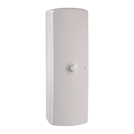
Publicidad
Enlaces rápidos
TYXAL DU
www.deltadore.com
Notice d'installation
FR
Installation guide
EN
Installationsanleitung
DE
Guida di installazione
IT
Manual de instalación
ES
Instrukcja instalacji
PL
Installatiehandleiding
NL
LS 14250 - 3,6 V - 1,2 Ah - Lithium
Autonomie 10 ans - Autonomy 10 years
868,30 MHz / 868,95 MHz (EN 300 220) - 100 m
IP
4
Mise en service / Activation / Inbetriebnahme / Messa in funzione / Puesta en servicio /
Rozruch / Ingebruikname
1
Ê
FR
AL et Com du détecteur universel. La borne AP est non connectée.
Ê Intruder: connect the intruder alarm wires to the AL and Com
EN
terminals, and the tamper alarm wires to the AP and Com
terminals. Other: connect the 2 wires of a sensor of your choice to
the universal detector AL and Com terminals. The AP terminal is
not connected.
Ê Einbruchmeldung: Schließen Sie die Leitungen des Melders an
DE
die Klemmen AL und Com an, die Leitungen des Selbstschutzes
an die Klemmen AP und Com. Technik: Schließen Sie die beiden
Drähte des Sensors Ihrer Wahl an die Klemmen AL und Com des
Universalmelders an. Die Klemme AP wird nicht belegt.
Ê
IT
del sensore universale. Il morsetto AP non è collegato.
Ê Intrusión: cablee los hilos de detección de intrusión en los bornes
ES
AL y Com, y los hilos de autoprotección en los bornes AP y Com.
Técnico: cablee los 2 hilos del sensor de su elección a los bornes
AL y Com del detector universal. El borne AP no se conecta.
Ê
PL
Ê Inbraak: sluit de kabels voor inbraakdetectie aan op de
NL
aansluitingen AL en Com, en de kabels voor zelfbescherming op
de aansluitingen AP en Com. Techniek: sluit de twee kabels van
de sensor van uw keuze aan op de aansluitingen AL en Com van
de universele detector. De aansluiting AP wordt niet aangesloten.
Consumption stand-by : 3,5 μA
Consumption : 14,2 mA max.
Ý
300m
-10°C / +70°C
+5°C / +40°C
IP 30 - IK 02
75 %
33 x 102 x 32 mm
59 gr.
R&TTE 1999/5/CE
Important product information (Ì)
2
Ë Mettez la pile en place en
respectant son sens puis
refermez le boîtier.
Ë Insert the battery and close
the unit.
Ë Setzen Sie die Batterie unter
Beachtung der Polarität ein
und schließen Sie dann das
Gehäuse.
Ë Posizionare la pila nel corretto
senso e chiudere la scatola.
Ë Coloque la pila respetando la
polaridad y cierre la caja.
Ë
Ë Plaats de batterij in de correcte
richting en sluit de behuizing.
Contenu / Contents / Inhalt / Contenuto / Contenido /
Instructions
Important
Product
Informations
1
Présentation / Presentation / Beschreibung / Presentazione / Presentación / Prezentacja /
Voorstelling
Le détecteur doit être associé à un système d'alarme DELTA DORE radio X3D.
FR
The detector must be associated with a DELTA DORE wireless X3D alarm system.
EN
Der Melder muss mit einer DELTA DORE Funk-Alarmanlage X3D verbunden werden.
DE
Il sensore deve essere associato ad un sistema d'allarme DELTA DORE radio X3D.
IT
El detector debe asociarse a un sistema de alarma DELTA DORE radio X3D.
ES
PL
De detector moet worden gekoppeld aan een alarmsysteem DELTA DORE radio X3D.
NL
2
Emplacement / Location / Einbauort / Posizionamento / Ubicación / Lokalizacja / Locatie
FR
longueur de câble doit être inférieure à 2 m).
The universal detector operates with a hard-wired sensor. Install the transmitter close to the sensor
EN
(cable length must not exceed 2 m).
DE
der Nähe des Melders an (Kabellänge max. 2 m).
IT
lunghezza del cavo deve essere inferiore a 2 m).
ES
cable debe ser inferior a 2 m).
PL
NL
(kabellengte moet minder dan 2 m bedragen).
3
Fixation / Mounting / Montage / Fissaggio / Fijación / Mocowanie / Bevestiging
1
Ê Séparez les 2 parties
Ë Tracez et percez les trous
FR
du boîtier.
D1 et D2.
Ê Open the unit.
Ë Mark and drill holes D1 and
EN
D2.
Ê Öffnen Sie das Gehäuse,
Ë Markieren Sie die
DE
indem Sie die zwei
Bohrstellen und bohren Sie
die Löcher D1 und D2.
Gehäuseteile trennen.
Ê Separare le 2 parti della
Ë Segnare e fare i fori D1 e
IT
D2.
scatola.
Ë Marque y taladre los
Ê Separe las 2 partes de la caja.
ES
agujeros D1 y D2.
Ê
Ë
PL
Ê Scheid de twee delen van de
Ë Markeer en boor de gaten
NL
D1 en D2.
behuizing.
/ Inhoud
2
3
D1
D2
Ø max = 3 mm
Ì Fixez le socle de l'émetteur
avec les vis V1 et V2.
Ì Attach the transmitter base with
the V1 and V2 screws.
Ì Befestigen Sie den Sockel des
Senders mit den Schrauben V1
und V2.
Ì Fissare il supporto dell'emettitore
con le viti V1 e V2.
Ì Fije el zócalo del emisor con los
tornillos V1 y V2.
Ì
Ì Bevestig de basis van de zender
met de schroeven V1 en V2.
V1
V2
Publicidad

Resumen de contenidos para DELTA DORE TYXAL DU
- Página 1 LS 14250 - 3,6 V - 1,2 Ah - Lithium Autonomie 10 ans - Autonomy 10 years Le détecteur doit être associé à un système d’alarme DELTA DORE radio X3D. The detector must be associated with a DELTA DORE wireless X3D alarm system.
- Página 2 Fonctionnement avec un d’alarme / Operation with an alarm system / Betrieb mit einer Alarmanlage / Funzionamento con un sistema d’allarme / Funcionamiento con el Voir notice (borne AP) et le switch B2 permet de choisir le mode de déclenchement immédiat ou retardé. d’intallation système Refer to system...


