Publicidad
Idiomas disponibles
Idiomas disponibles
Enlaces rápidos
IB519084EN
Installation Instructions – VT3 LED Vaportight Luminaire Installation
Instructions d'installation – Luminaire DEL étanche à la vapeur VT3
Instrucciones de instalación – Instalación de la luminaria VT3 LED
Vaportight
WARNING
Risk of Fire, Electrical shock, Cuts and or other
Casualty Hazards. This product must be installed in
accordance with the applicable installation code by
a qualified electrician or a person familiar with the
construction and operation of the product and the
hazards involved. Eaton assumes no responsibility
for claims brought about by improper or careless
installation or handling of this product.
WARNING
Risk of Fire and Electric Shock. If not qualified, consult
an electrician.
IMPORTANT: Read carefully before installing fixture. Retain for future reference.
ATTENTION Receiving Department:
Note actual fixture description of any shortage or noticeable damage on delivery receipt. File claim for common carrier
(LTL) directly with carrier. Claims for concealed damage must be filed within 15 days of delivery. All damaged material,
complete with original packing must be retained.
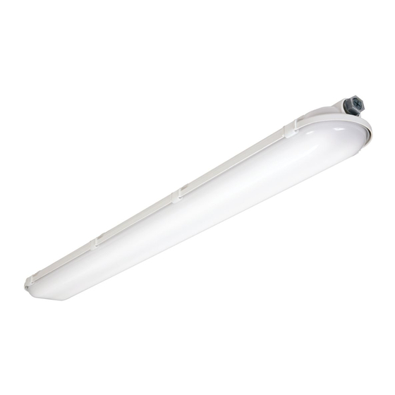
VT3 Description
The VT3 LED is a Vaportite fixture using a reinforced fiberglass housing with a high impact diffuser. The fixture is suitable
for interior and exterior applications and can be surface or chain mounted. The VT3 LED has been designed for maximum
operation in commercial institutional and industrial environments and is suited for ambient temperatures of -20°C to
25°C, with some models rated to 55C. It is also rated for wet locations and has IP ratings of IP65, IP66, IP67 , and IP69.
CAUTION
Edges May Cut. Handle with care.
CAUTION
Risk of Burn. Disconnect power and allow fixture to cool
before handling fixture.
N
otice:
Minimum 90° supply conductors.
N
otice:
Green ground screw provided in proper location.
Do not relocate.
N
ote:
Specifications and dimensions subject to change
without notice.
Brand Logo
reversed out of
black
INS #
INS #
Publicidad

Manuales relacionados para Eaton Metalux VT3 Serie


Resumen de contenidos para Eaton Metalux VT3 Serie
- Página 1 Risk of Burn. Disconnect power and allow fixture to cool hazards involved. Eaton assumes no responsibility before handling fixture. for claims brought about by improper or careless otice: Minimum 90°...
- Página 2 Any wiring connections necessary can be made. (Figure 4.) Gear Tray V Bracket (P & W Models Only) Sheet Metal Screws (2) (P & W Models Only) Hex Nut (2) Figure 2. Figure 4. EATON IB519084EN Installation instructions...
-
Página 3: Electrical Supply Connection
Liquid-Tight Conduit With Seal Apply Bead Of Silicone In Groove For Ip69 Only Figure 5. Figure 7. Tighten Hub Locknut Firmly Against Housing Gland Nut Sealing Ring Sealing Gasket Grounding Ferrule Body Figure 6. Figure 8. EATON IB519084EN Installation instructions... - Página 4 2 red “converter connector” wires with supplied wire nut. The test button & indicator light is located in the EM housing for remote units and on the gear tray for integral units. EATON IB519084EN...
- Página 5 électricien qualifié ou une personne familière avec MISE EN GARDE la construction et le fonctionnement du produit, ainsi qu’avec les risques inhérents. Eaton n’assume aucune Risque de brûlures. Débranchez la source d’alimentation et responsabilité quant aux réclamations dues à une laissez refroidir le luminaire avant de le manipuler.
- Página 6 Vous pouvez faire tous les raccords de câblage nécessaires. (Figure 4). Plaque métallique Support en V (modèles P et W seulement) Vis à tôle (2) (modèles P et W Figure 2. seulement) Écrous hexagonaux (2) Figure 4. EATON IB519084EN Instructions d’installation...
- Página 7 Appliquez une perle de silicone dans la rainure pour IP69 seulement Serrez fermement le contre-écrou contre le boitier Figure 7. Écrou de presse-garniture Bague d’étanchéité Garniture d’étanchéité Plot Bague de mise à la terre Corps Figure 6. Figure 8. EATON IB519084EN Instructions d’installation...
-
Página 8: Pile De Secours
(2) fils rouges (connecteur/convertisseur) avec les deux (2) capuchons de connexion fournis. Le bouton d’essai et le témoin sont situés dans le boitier de l’appareil de secours pour les appareils distincts ou sur la plaque métallique pour les appareils intégrés. EATON IB519084EN Instructions d’installation... - Página 9 Riesgo de Quemaduras. Desconecte la energía y deje enfriar la de instalación aplicable. Eaton no asume ninguna luminaria antes de manipularla. responsabilidad por los reclamos ocasionados por otice: Conductores de alimentación para un mínimo de...
- Página 10 Se puede hacer cualquier conexión de cableado necesaria. (Figura 4.) Bandeja de engranajes Soporte V (solo para los modelos P & W) Tornillos de chapa (2) (solo para los modelos P & W) Tuerca hexagonal (2) Figura 2. Figura 4. EATON IB519084EN Instrucciones de instalación...
- Página 11 Ip69 Apriete firmemente la contratuerca Figura 7. del hub contra la cubierta Tuerca de glándula Anillo de sellado Junta de sellado Férula de puesta a tierra Cuerpo Figura 6. Figura 8. 11 11 EATON IB519084EN Instrucciones de instalación...
- Página 12 2 cables rojos del "conector del convertidor" con la tuerca de cable suministrada. El botón de prueba y la luz indicadora se encuentran en la carcasa EM para unidades remotas y en la bandeja de engranajes para unidades integrales. EATON IB519084EN Instrucciones de instalación...
- Página 16 Warranties and Limitation of Liability Please refer to www.eaton.com/LightingWarrantyTerms for our terms and conditions. Garanties et limitation de responsabilité Veuillez consulter le site www.eaton.com/LightingWarrantyTerms pour obtenir les conditions générales. Garantías y Limitación de Responsabilidad Visite www.eaton.com/LightingWarrantyTerms para conocer nuestros términos y condiciones.