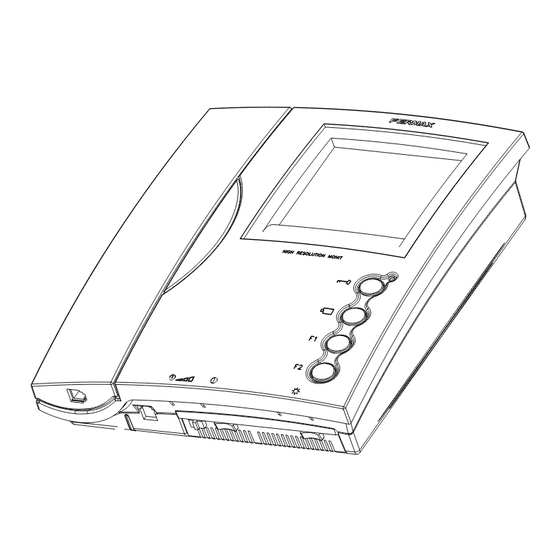
Fermax LOFT BUS2 Manual De Instrucciones
Conector monitor
Ocultar thumbs
Ver también para LOFT BUS2:
- Manual de instalador (80 páginas) ,
- Esquemas de instalacion (52 páginas) ,
- Manual de instrucciones (28 páginas)
Publicidad
Enlaces rápidos
L L L L L OFT
OFT
OFT
OFT
OFT
Cod 97470 V03_09
Conector Monitor - Monitor Connector -
Connecteur Moniteur- Montageplatte Monitor - Connettore Monitor
P1
CT
NO TERM
T
F2
JP1 JP2
TERM
F1
-
B In
B In
B Out
B Out
CN1
E
- Bus de comunicaciones audio+video (sin polaridad)
B,B In
- Conexión monitor/teléfono adicional
B,B out
Conexión siguiente monitor/teléfono en cascada
CT
Activación cámara auxiliar (salida 10Vdc)
T, -
Conexión pulsador de llamada puerta vivienda (P1)
Funciones adicionales (salida negativo «-»).
F1, F2
Corriente máxima por pulsador F1,F2: 50mA a 12Vdc
En instalaciones en cascada:
- Colocar el puente JP1 en la posición NO TERM en los monitores de planta primera y
plantas intermedias.
JP1
- Colocar el puente JP1 en la posición TERM en el último monitor (última planta).
En instalaciones en distribuición, colocar el puente JP1 en la posición NO TERM en todos
los monitores.
- Cuando sólo hay un monitor
por vivienda, colocar el puente JP2 en la posición «NO TERM».
JP2
- Si tenemos dos monitores (o incluso monitor y teléfono), se debe situar
posición «TERM» en ambos terminales.
EN
- Audio+Video comunication bus (polarity free)
B,B In
- Additional monitor/telephone connection
B,B out
Connection to next monitor/telephone on the circuit
CT
Auxiliary camera activation (10 Vdc output)
T, -
Call button connection (P1)
Additional functions (negative output).
F1, F2
Maximum current per pussbutton F1, F2: 50mA with 12Vdc
In cascade systems:
- Set up the JP1 switch in the NO TERM position on the first and mezzanine floor
monitors.
JP1
- Set up the JP1 switch in the TERM position on the last monitor (top floor).
In distribution systems, set up the JP1 switch in the NO TERM position on all the monitors.
- When there is only one monitor per residence, set up the JP2 switch in the NO TERM position.
JP2
- If we have two monitors (or even a monitor and a telephone) the JP2 switch should be
set up in the TERM position on both terminals
B B B B B US2
US2
US2
US2
US2
1
4
3
2
el puente JP2 en la
F
- Bus de communication audio+vidéo (sans polarité)
B,B In
- Connexion moniteur/poste supplémentaire
B,B out
Connexion moniteur/poste en cascade suivant
CT
Activation caméra auxiliaire (sortie 10Vdc)
T, -
Raccordament bouton-poussoir d'appel porte du logement (P1)
Fonctions supplémentaires (sortie négatif).
F1, F2
Courrant maximum du bouton-poussoir F1,F2: 50mA a 12Vdc
Sur des installations en cascade :
- Placer le commutateur JP1 sur la position NO TERM sur les moniteurs du premier étage
et des étages intermédiaires.
JP1
- Placer le commutateur JP1 sur la position TERM sur le dernier moniteur (dernier étage).
Sur des installations en distribution, placer le commutateur JP1 sur NO TERM pour tous les
moniteurs.
- Lorsqu'il n'y a qu'un seul moniteur par logement, placer le commutateur JP2 sur « NO TERM ».
JP2
- S'il y a deux moniteurs (voire moniteur et poste), l'on doit placer le commutateur JP2 sur
« TERM » pour les deux terminaux.
D
- Kommunikations bus audio+video (ohne Polarität)
B,B In
- Anschluss zusätzlicher Monitor/Telefone
B,B out
Anschluss an den nachfolgenden Monitor/Telefon in Kaskadenanordnung
Aktvierung Kamera (10 Vdc)
CT
Anschluss Ruftaste Wohnungdtür (P1)
T, -
Zusatzfunktionen (Negativausgang).
F1, F2
Maximale Strömmung pro Taster F1, F2: 50mA mit 12Vdc
Bei Anlagen mit Kaskadenanordnung:
- Stecken Sie die Steckbrücke JP1 bei den Monitoren im ersten Stockwerk und den
Zwischenstockwerken auf NO TERM um.
JP1
- Stecken Sie die Steckbrücke JP1 beim letzten Monitor (letztes Stockwerk) auf TERM um.
Bei Anlagen mit Verzweigungen stecken Sie die Steckbrücke JP1 bei allen Monitoren auf NO
TERM um.
- Falls nur ein Monitor pro Wohnung vorhanden ist, stecken Sie die Steckbrücke JP2 auf „NO TERM„ um.
JP2
- Falls zwei Monitoren vorhanden sind (bzw. ein Monitor und ein Telefon), muss die Steckbrücke an
beiden Geräten auf „TERM„ umgesteckt werden
P
- Bus de comunicação audio+video (sem polaridade)
B,B In
- Ligação monitor/telefono adicional
B,B out
Conexão seguinte monitor/telefone em série
CT
Activação telecâmara auxiliar (saída 10Vdc)
T, -
Ligação do botão de chamada porta da vivenda (P1)
Funções adicionais (saída negativo «-»).
F1, F2
Corrente máxima por botão F1,F2: 50mA a 12Vdc
Nas instalações em série:
- Colocar o jumper JP1 na posição NO TERM nos monitores do 1º andar e andares
intermediários.
JP1
- Colocar o jumper JP1 na posição TERM no último monitor (última planta).
Nas instalações em distribuição, colocar o jumper JP1 na posição NO TERM em todos
monitores.
- Quando somente tenha um monitor por vivenda, colocar o jumper JP2 na posição "NO TERM".
JP2
- Se temos dois monitores (ou monitor e telefone), deve-se situar o jumper JP2 na posição
"TERM" em ambos terminais.
Publicidad

Resumen de contenidos para Fermax LOFT BUS2
- Página 1 L L L L L OFT B B B B B US2 - Bus de communication audio+vidéo (sans polarité) Cod 97470 V03_09 B,B In - Connexion moniteur/poste supplémentaire Conector Monitor - Monitor Connector - B,B out Connexion moniteur/poste en cascade suivant Connecteur Moniteur- Montageplatte Monitor - Connettore Monitor Activation caméra auxiliaire (sortie 10Vdc) T, -...
- Página 2 B In B In B Out B Out B In FAULT FAULT B Out DERIVACION DERIVACION B Out B Out SPLIT SPLIT B In B Out B Out FAULT FAULT BUS-2 INPUT PREV DISTRIB B Out BUS-2 INPUT PREV DISTRIB www.fermax.com...


