Tabla de contenido
Publicidad
Idiomas disponibles
Idiomas disponibles
Enlaces rápidos
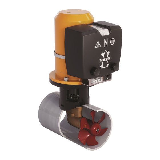
ø 150 mm
C o p y r i g h t © 2 0 0 0 , 2 0 0 4 Ve t u s d e n O u d e n n . v. S c h i e d a m H o l l a n d
35 kgf
55 kgf
Installatie instructies
Installation instructions
Einbauanleitung
Instructions d'installation
Instrucciones de instalación
Istruzioni per il montaggio
NEDERLANDS
ENGLISH
DEUTSCH
FRANÇAIS
ESPAÑOL
ITALIANO
2
4
6
8
10
12
Publicidad
Tabla de contenido

Manuales relacionados para Vetus STERN THRUSTER


Resumen de contenidos para Vetus STERN THRUSTER
- Página 1 Installatie instructies Installation instructions Einbauanleitung Instructions d’installation Instrucciones de instalación Istruzioni per il montaggio NEDERLANDS ENGLISH DEUTSCH FRANÇAIS ESPAÑOL ITALIANO 35 kgf 55 kgf ø 150 mm C o p y r i g h t © 2 0 0 0 , 2 0 0 4 Ve t u s d e n O u d e n n . v. S c h i e d a m H o l l a n d...
- Página 2 Inleiding Gebruik De Vetus ‘boegschroeven’ type ‘35 kgf’ en het type ‘55 kgf’ kun- Raadpleeg voor het gebruik van de hekschroef de bedienings- nen met behulp van deze montageset (flens en de bijbehoren- handleiding van de geïnstalleerde boegschroef. de tunnel) eenvoudig als ‘hekschroef’ worden geïnstalleerd.
- Página 3 NEDERLANDS Indien de spiegel onvol- doende hoogte biedt voor Alleen bij ‘35 kgf’: de montage van de hek- Plaats de extra pakking schroef kan eventueel een in de flens. schuin vlak worden gemaakt om de hek- Breng op het afdichtvlak schroef te monteren.
- Página 4 General The reliability of the stern thruster is entirely dependent on the quality of the installation. Nearly all problems are caused by faults or inaccuracies which occur during the installation. It is therefore of utmost importance to follow and check the points mentioned in this manual.
- Página 5 Installation of the flange Install the 2 supplied zinc anodes. At the place of installation of the stern thruster attach the drill pattern at the outside and mark the holes. The drill pattern is on the centre page. IMPORTANT: The centerline of the drill pattern must be pre- cisely horizontally and at least 150mm below the waterline.
- Página 6 Einführung Einsatz Die Vetus-‘Bugschrauben’ des Typs ‘35 kgf’ und des Typs Zum Einsatz der Heckschraube lesen Sie bitte die ‘55 kgf’ können mit Hilfe dieses Montage-Sets (Flansch und Bedienungsanleitung der installierten Bugschraube. dazugehöriger Tunnel) einfach als ‘Heckschraube’ installiert werden. Dank dieses Spezialflansches bleibt der Elektromotor im Schiff.
- Página 7 DEUTSCH Bietet der Spiegel für den Einbau der Heckschraube Nur bei Typ ‘35 kgf’: nicht die ausreichende Die extra Packung im Höhe, kann zur Montage Flansch anbringen. der Schraube gegebenen- falls eine Schräge ge- Auf die Dichtfläche des schaffen werden. Beden- Flansches ( ) tragen ken Sie, daß...
- Página 8 Introduction Utilisation Les hélices d’étrave Vetus de type ‘35 kgf’ et ‘55 kgf’ peuvent Pour l’utilisation de l’hélice de poupe consultez le mode d’em- être facilement installées comme hélice de poupe grâce à ce kit ploi de l’hélice d’étrave installée.
-
Página 9: Mise En Place De La Bride
FRANÇAIS Si l’arcasse présente une hauteur insuffisante pour Pour le type ‘35 kgf’ le montage de l’hélice de uniquement : poupe, on peut éventuel- Placer le joint supplé- lement créer une surface mentaire dans la bride. inclinée pour monter l’héli- ce de poupe. -
Página 10: Introducción
Introducción Las ‘hélices de estrave’ de Vetus tipo ‘35 kgf’ y el tipo ‘55 kgf’ Para el uso de la hélice de popa, consúltense las instrucciones se pueden instalar de forma sencilla como `hélice de popa’ con de manejo de la hélice de estrave instalada. -
Página 11: Instalación De La Brida
ESPAÑOL Si el espejo no ofrece la altura suficiente para el Sólo en el tipo ‘35 kgf’: montaje de la hélice de Coloque la junta extra popa, se puede elaborar en la brida. eventualmente una super- ficie oblicua para montar Aplicar en la superficie de la hélice de popa. - Página 12 Introduzione Funzionamento Le ‘eliche di prua’ della VETUS tipo ‘35 kgf’ e ‘55 kgf’ possono Per il funzionamento dell’elica di poppa consultare il manuale di facilmente essere installate come ‘eliche di poppa’, seguendo istruzioni dell’elica di prua installata. le istruzioni di questo set di montaggio (flangia e tunnel).
- Página 13 ITALIANO Se lo specchio di poppa non offre un’altezza suffi- Solo per il tipo da ciente per il montaggio ‘35 kgf’: Inserire una dell’elica, si può eventual- guarnizione ausiliaria mente applicare un piano sotto la flangia. inclinato. Ricordare, in questo caso, di protegge- re il tunnel dalla forza del- Applicare della pasta sigil- l’acqua durante la naviga-...
-
Página 14: Principal Dimensions
Hoofdafmetingen Principal dimensions Hauptabmessungen ‘35 kgf’ 1 : 5 2.0524 Installation set for stern thruster ‘35 kgf’ and ‘55 kgf’... -
Página 15: Dimensions Principales
Dimensions principales Dimensiones principales Dimensioni principali ‘55 kgf’ 1 : 5 2.0524 Installation set for stern thruster ‘35 kgf’ and ‘55 kgf’... - Página 16 FOKKERSTRAAT 571 - 3125 BD SCHIEDAM - HOLLAND - TEL.: +31 10 4377700 - TELEX: 23470 TELEFAX: +31 10 4372673 - 4621286 - E-MAIL: sales@vetus.nl - INTERNET: http://www.vetus.nl Printed in the Netherlands 2.0524 I.ST150 12-00 Rev. 05-04...