Tabla de contenido
Publicidad
Idiomas disponibles
Idiomas disponibles
Enlaces rápidos
Federal regulations require all ceiling
fans with light kits manufactured or
imported after January 1, 2009, to
limit total wattage consumed by the
light kit to 190W. Therefore, this fan
is equipped with a wattage limiting
device.
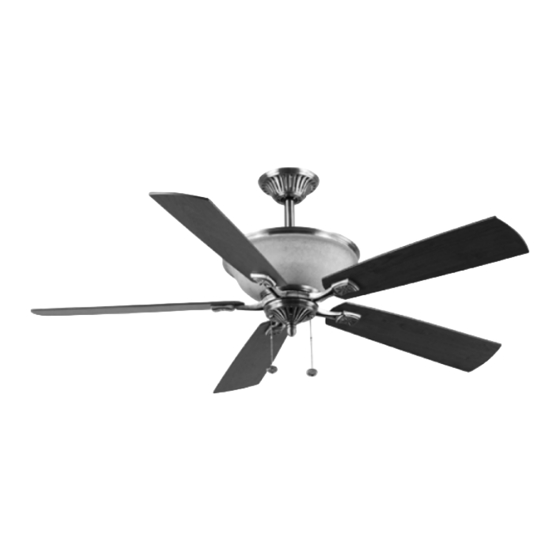
Installation Guide
For Model:
DTB54EP5CM
E192641
net weight of fan: 23.37 lb. (10.6 kg)
READ THESE INSTRUCTIONS AND
SAVE THEM FOR FUTURE USE
Table of Contents:
Safety Information. pg. 1
Package Contents. pg. 2
Preparation. pg. 3
Initial Installation. pg. 3
Wiring. pg. 4 - 5
Final Installation. pg. 5 - 7
Fan Operation. pg. 7
Care and Maintenance. pg. 8
Troubleshooting. pg. 8
Warranty. pg. 9
Parts Replacement. pg. 9
Publicidad
Capítulos
Tabla de contenido

Manuales relacionados para Litex Industries DTB54EP5CM


Resumen de contenidos para Litex Industries DTB54EP5CM
-
Página 1: Tabla De Contenido
190W. Therefore, this fan is equipped with a wattage limiting device. Installation Guide For Model: DTB54EP5CM Table of Contents: Safety Information. pg. 1 Package Contents. pg. 2 Preparation. pg. 3 Initial Installation. pg. 3 Normal Or Angle Style Fan Mounting. -
Página 2: Safety Information
SAFETY INFORMATION Please read and understand this entire manual before attempting to assemble, install or operate the product. If you have any questions regarding the product, please call customer service at 1-800-527-1292, 8:30 a.m.-5:00 p.m., CST, Monday-Friday. 1. Before you begin installing the fan, disconnect the power by removing fuses or turning off circuit breakers. CAUTION: Read all instructions and safety information before installing your new fan. -
Página 3: Package Contents
PACKAGE CONTENTS Part Description Quantity Downrod Canopy Mounting Bracket Motor Housing Yoke Cover Blade Blade Arm Switch Housing Plate 15 Watt Bulb Switch Housing Motor Screw (in motor) 3/16 Blade Screw (in hardware pack) 5.4M/M Lock Washer (in motor) Blade Washer (in hardware pack) E3 Wire Connector (in hardware pack) Blade Balancing Kit (in hardware pack) Canopy Mounting Screw... -
Página 4: Preparation
PREPARATION 1. Before beginning assembly and installation of product, make sure all parts are present. Compare parts with "Package Contents" list and diagrams on the previous page. If any part is missing or damaged, do not attempt to assemble, install or operate the product. Contact customer service for replacement parts as indicated at the bottom of page 2. -
Página 5: Normal Or Angle Style Fan Mounting
NORMAL OR ANGLE STYLE FAN MOUNTING 1. Insert downrod (A) through canopy (B), canopy cover (X) and yoke cover (E). (Note: Canopy cover (X) must be turned with the shiny side toward the motor housing (D). [Fig. 1] Thread wires from motor housing (D) through downrod (A). -
Página 6: Final Installation
WIRING (continued from previous page) FAN AND LIGHT CONTROLLED BY SEPARATE WALL SWITCHES. 1C. If you intend to control the fan and light with separate wall Fig. 1C switches, wire as indicated in the instructions in 1A except SWITCHED FAN POWER connect BLUE wire from fan to the BLACK supply from the SWITCHED WHITE (NEUTRAL) - Página 7 FINAL INSTALLATION (continued from previous page) 3. Position blade arm (G) under blade (F) and attach blade arm (G) to blade (F) with blade screws (L) and blade washers (N). Do not tighten blade screws (L) until each blade screw (L) has been started.
-
Página 8: Motor Housing Bulb Replacement
FINAL INSTALLATION (continued from previous page) 9. Pull chain extensions (T) supplied in one of the hardware packs or custom pull chain extensions (not included) may be attached to fan and light pull chains. [Fig. 9] NOTE: This fan is remote control adaptable (remote control not included) Fig. -
Página 9: Care And Maintenance
CARE AND MAINTENANCE At least twice each year, lower canopy (B) to check downrod (A) assembly, and then tighten all screws on the fan. Clean motor housing (D) with only a soft brush or lint-free cloth to avoid scratching the finish. Clean blades (F) with a lint-free cloth. -
Página 10: Warranty
Contact Litex Customer Service at 1-800-527-1292 to arrange for return of fan. Return fan, shipping prepaid, to Litex Industries, Ltd. We will repair or ship you a replacement fan, and we will pay the return shipping cost. -
Página 11: Indice De Materias
Por lo tanto, este ventilador tiene un aparato que sirve para limitar el vatiaje. Guía de instalación Para modelo: DTB54EP5CM Indice de materias: Información de seguridad. Pág. 1 Contenido de paquete. Pág. 2 Preparación. Pág. 3 Instalación inicial. Pág. 3 Estilo de montaje del ventilador normal o en ángulo. -
Página 12: Información De Seguridad
INFORMACION DE SEGURIDAD Por favor lea el instructivo entero antes de tratar de ensamblar, instalar o hacer funcionar el producto. Si tiene alguna pregunta acerca del producto, por favor llame al servicio al cliente al 1-800-527-1292, de 8:30 a.m. a 5:00 p.m., hora central, de lunes a viernes. -
Página 13: Contenido Del Paquete
CONTENIDO DEL PAQUETE Pieza Descripción Cantidad Vástago Cubierta Soporte de montaje Bastidor del motor Cubierta del yugo Paleta Brazo para la paleta Placa de la caja del interruptor Bombilla de 15 vatios Caja del interruptor Tornillo del motor (en el motor) Tornillo para la paleta 4,76 mm (en paquete de artículos de ferretería) Arandela de seguridad 5,4M/M... -
Página 14: Preparación
PREPARACION 1. Antes de empezar con el ensamblaje e instalación del producto, asegúrese de tener todas las piezas. Compare las piezas con la lista y los diagramas del "Contenido del paquete" en la página anterior. Si falta alguna pieza o se encuentra dañada, no trate de ensamblar, instalar o hacer funcionar el producto. -
Página 15: Estilo De Montaje Del Ventilador Normal O En Ángulo
ESTILO DE MONTAJE DEL VENTILADOR NORMAL O EN ANGULO 1. Introduzca el vástago (A) en la cubierta (B), decoración para la cubierta (X) y la cubierta del yugo (E). Nota: Se tiene que voltear la decoración para la cubierta (X) para que el lado brillante dé al bastidor del motor (D). -
Página 16: Instalación Final
CONEXION DE LOS CABLES (continúa de la página anterior) VENTILADOR Y LUZ CONTROLADOS POR 1C. Si usted piensa controlar la luz y el ventilador con INTERRUPTORES DE PARED INDEPENDIENTES. interruptores distintos, haga las conexiones según las Fig. 1C ENERGIA ELECTRICA DEL INTERRUPTOR AL VENTILADOR instrucciones en el 1A excepto conecte el cable AZUL del ENE RGIA BLANCO (NEUTRAL) - Página 17 INSTALACION FINAL (continúa de la página anterior) 3. Coloque el brazo para la paleta (G) debajo de la paleta (F) y asegure el brazo para la paleta (G) a la paleta (F) con tornillos para la paleta (L) y arandelas para la paleta (N). No apriete los tornillos para la paleta (L) hasta que se haya introducido cada tornillo para la paleta (L).
-
Página 18: Reemplazo De Bombilla Del Bastidor Iluminado
INSTALACION FINAL (continúa de la página anterior) 9. Se pueden fijar las extensiones para las cadenas de encendido (T) provistas en uno de los paquetes de artículos de ferretería a las cadenas de encendido para el ventilador y la luz o usar extensiones para cadenas de encendido hechas a medida (no incluidas). -
Página 19: Cuidado Y Mantenimiento
CUIDADO Y MANTENIMIENTO Baje Ia cubierta (B) para inspeccionar el conjunto del vástago (A) por lo menos dos veces al año, y luego apriete todos los tornillos del ventilador. Limpie el bastidor del ventilador (D) solamente con un cepillo suave o un paño que no tenga pelusa para no rayar el acabado. -
Página 20: Garantía
Ni Litex Industries ni el fabricante se harán responsables por lo que pasa por una instalación inadecuada o el uso impropio de este producto. La compañía no se hará responsable en ningún caso de ningún daño emergente por incumplimiento de esta o cualquier otra garantía expresada o implicada en absoluto.