Tabla de contenido
Publicidad
Idiomas disponibles
Idiomas disponibles
Enlaces rápidos
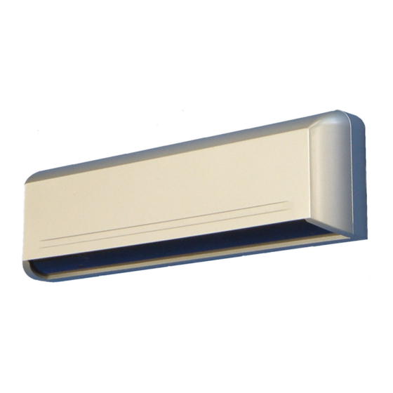
OA-203C
MANUFACTURER'S STATEMENT
Read this Operation Manual carefully before use, to ensure proper operation of this Optex sensor.
Failure to read this Operation Manual may cause improper sensor operation and may result in serious injury or death.
This product is a non-contact activating switch intended for mounting on the header of an automatic door.
Do not use it for any other applications; otherwise proper operation and safety cannot be guaranteed.
Cautions:
1. Follow the instructions (especially
2. When setting the sensor's area pattern, make sure there is no traffic around the installation site.
3. Before turning the power on, check the wiring to prevent damage or malfunction of equipment that is connected to the sensor.
4. Do not wash, disassemble, rebuild or repair the sensor by yourself; otherwise it may cause electric shock or breakdown of the
sensor.
5. Only use the sensor as specified in the supplied instructions.
6. Be sure to install the sensor in accordance with the local laws and standards of your country.
7. Before leaving the jobsite, be sure that this sensor is operating properly and instruct the building owner/operator on proper
operation of the door and this sensor.
SPECIFICATIONS
: OA-203C
Model
: Silver / Black / White
Cover color type
: 3.0m (9'10") Max.
Mounting Height
: See "Detection Area"
Detection Area
: Active Infrared Reflection Method
Detection Method
: ±4° adjustable by 1° every one click
Detection Angle
(Deep / Shallow)
Adjustments
: ±7° adjustable by 3.5° every one click
Detection Width
(Right / Left)
Adjustments
: 12 to 30V AC / DC
Power Supply
: 160mA Max. (at 12V AC)
Current Draw
: Green / Stand-by
Operation Indicator
Red
Orange / Other Row Detection Active
OUTER DIMENSIONS
221 ( 8 11/16" )
125 ( 4 15/16" )
36 ( 1 7/16" )
Note
) in this Operation Manual when installing and adjusting the sensor.
/ 1st Row Detection Active
43 ( 1 11/16" )
mm (inch)
Output
Relay Hold Time
Response Time
Operating Temperature
Weight
Accessories
*The specifications herein are subject to change without
prior notice due to improvements.
29.9 ( 1 3/16" )
GREY
: POWER 12to30V AC/DC
WHITE
: OUTPUT
COM.
YELLOW : OUTPUT
N.O.
GREEN : OUTPUT
N.C.
CURRENT DRAW :XXXmA Max
OUTPUT : Form C 50V0.3A Max
(RESISTANCE LOAD)
OPERATION INDICATOR
GREEN
: STAND-BY
RED
: 1st ROW DETECTION
ORANGE : OTHER AREA DETECTION
1 : Connector
2 : Sensitivity Switch
3 : Mounting holes
4 : Dipswitches
5 : Area Adjustment Tool
: "Form C" relay 50V 0.3A Max.
(Resistance Load)
: 0.5 sec.
: < 0.3 sec.
: -20°C to +55°C (-4°F to +131°F)
: 200g (7.1oz)
: 1 Cable 3m (9'10")
2 Mounting Screws
1 Operation Manual
1 Mounting Template
1 Area Adjustment Tool
SENSITIVITY
ADJUSTMENT
SHALLOW
DEEP
SWITCH
SCREW
ADJUSTMENT
ON
L L
M
H
4ROW
7 8
(1 x 4)
(1 x 4)
3ROW
7 8
LEFT
RIGHT
SNOW MODE
2ROW
TIMER
FREQUENCY
SWITCH
7 8
2sec
15se
180sec.
1ROW
(3.5 x 2)
(3.5 x 2)
1 2
1 2
1 2
1 2
7 8
6 : Area Adjustment Screw
7 : Width Adjustment Shutters
8 : Operation Indicator
9 : Detection Window
5911183 2006.5
AREA WIDTH
A
ADJUSTMENT
S
LEFT
RIGHT
ELIMINAT
ELIMINAT
5726130
Publicidad
Tabla de contenido
Solución de problemas

Manuales relacionados para Optex PROSAFE OA-203C


Resumen de contenidos para Optex PROSAFE OA-203C
- Página 1 MANUFACTURER’S STATEMENT 5911183 2006.5 Read this Operation Manual carefully before use, to ensure proper operation of this Optex sensor. Failure to read this Operation Manual may cause improper sensor operation and may result in serious injury or death. This product is a non-contact activating switch intended for mounting on the header of an automatic door.
- Página 2 INSTALLATION Remove the cover and attach the sensor with screws. Max. Mounting Template 1. Affix the Mounting Template to the mounting surface. Plug the Connector for the sensor to that for the cable. 2. Drill two mounting holes (ø 3.4mm or 1/8”). Supply power to the sensor.
- Página 3 ADJUSTMENT Adjusting the Pattern Width O p e n s Eliminate Setting the Width Eliminate Eliminate A l l A r e a s 1 2 7 8 adjustment shutters Pattern when changed 7 Pattern when changed 7 Adjusting the Width Angle Pattern when Standard to Left to Right...
-
Página 4: Troubleshooting
Contact your installer or the sales engineer if: - you need to change the settings or replace the sensor. - the trouble still persists after checking and remedying as described above. OPTEX CO., LTD. Optex Technologies, Inc. Secumatic b.v. (ISO 9001 Certified by LRQA) 5-8-12 Ogoto Otsu 520-0101, Japan 3882 Del Amo Blvd., Suite 604, Torrance,... -
Página 5: Declaración Del Fabricante
5911183 2006.5 Lea este Manual de Funcionamiento atentamente antes de utilizar el sensor, para garantizar un uso correcto de este sensor Optex. La no lectura de este Manual de Funcionamiento puede inducir a un uso incorrecto del sensor y producir lesiones graves o incluso la muerte. -
Página 6: Instalacion
INSTALACION Retirar la cubierta y fijar el sensor con los tornillos. Max.3m Plantilla de montage 1. Fijar la plantilla de montaje sobre la superficie de montaje. Enchufar el conector del sensor al del cable. 2. Perforar dos orificios de montaje (ø3,4 mm o 1/8"). Conectar la alimentación del sensor. - Página 7 AJUSTES Ajuste del ancho del área Elimina Elimina Elimina A b r e t o d a s Ajuste el ancho del área 1 2 7 8 l a s á r e a s con obturadores de ajustes de ancho. Area cuando cambia 7°...
-
Página 8: Solución De Problemas
Contactar al instalador o al ingeniero de ventas si: - necesita cambiar los ajustes o cambiar el sensor. - el problema persiste después de revisar y remediar el problema de la forma arriba descrita. OPTEX CO., LTD. Optex Technologies, Inc. Secumatic b.v.