
Manuales relacionados para Ergomotion Motion Air


Resumen de contenidos para Ergomotion Motion Air
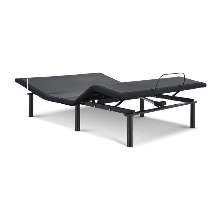
- Página 1 Owner’s Manual Actual product appearance and functionality may vary from photographs, illustrations and descriptions included in this manual.
-
Página 2: Tabla De Contenido
table of contents Safety Precautions and Usage Statements . . . . . . . . . . . . . . . . . . . . . . . . . . . . . . . . . . . . . . . . . . . . . . . . . . . . . . . . . . . . . . . . . . . . . 1-4 Parts List . - Página 3 safety precautions and usage statements safety precautions and usage statements Attention: Important Safety Disclaimers Read all instructions before using your adjustable base. Save these instructions. SAFETY If the plug does not fit your outlet, contact a qualified electrician to install a suitable outlet .
-
Página 4: Safety Precautions And Usage Statements
The bed base should only be plugged directly into a grounded TOLERANCE All Ergomotion adjustable foundations, depending on make and model, are designed and manufactured to perform and function within designated quality control parameters. Bases are subject to meticulous and rigorous inspections during wall outlet or surge protector (strongly recommended). - Página 5 safety precautions and usage statements The angle (designated “b” in figure 1) between the flat section and foot section For spot cleaning, wipe area with a light damp sponge or vacuum with a soft for various configurations of the mattress support platform shall be ± 3°, which brush attachment to remove particles .
- Página 6 safety precautions and usage statements IMPORTANT DO’S AND DON’TS FCC Compliance: NOTE: This equipment has been tested and found to comply with • Plug your adjustable base into a power surge protector . the limits for a Class B digital device, pursuant to part 15 of the FCC •...
-
Página 7: Parts List
parts list Before discarding the packing materials, ensure all the parts are accounted for. All electronics and components that need to be installed are located in boxes under the base or attached to the frame. Wireless Remote Control and AAA Batteries (3) Mattress Retainer Bar* Legs (6) Power Cord... -
Página 8: Base And Remote Overview
base and remote overview Head Motor Lifts and lowers Lifts and lowers foot portion of the head portion of base. the base. Lower Head/Foot sec- Lift Head/Foot section tion simultaneously simultaneously Control Box Foot Motor... -
Página 9: Quick Reference Guide
quick reference guide Not to scale. For illustration purposes only. Read all instructions before beginning installation. ELECTRONICS OVERVIEW Power Cord Power Supply Control Input Cord Foot Motor Head Motor Wireless Battery Backup Strap Remote If installing a split unit, see pages 16-17... -
Página 10: Installation Guide
4a . Then secure the Pin with a Clip . Remove the Pins and Clips that are secured to the base (refer to Fig .C1) so that you may attach the corresponding brackets and motors . Fig.C1 Fig.C2 For customer support, visit www.ergomotion.com or call: 1-888-550-3746... - Página 11 . Insert a washer into each side hole of Fig.F2 Fig .H1, and align the "F" holes with the the Head Motor Bracket . corresponding head bracket holes on the base (Fig .H2) . For customer support, visit www.ergomotion.com or call: 1-888-550-3746...
- Página 12 installation guide Secure the Pin with another washer and Fig.H2 Fig.I3 a Clip . b . Slide a pin through the Foot Motor Fig.H3 Bracket holes and secure it with a Clip (Fig .H3) . Washer Washer Clip STEP 10 Remove the Pins from the Foot Motor Fig.J1 STEP 9...
- Página 13 installation guide d . Slide a Pin through the washers and Fig.J4 To sync two bases with the Sync Cord, see pages 16-17. holes in the Head Motor, then secure the Pin with a Clip . STEP 14 To install the legs, connect all of the four 3" leg segments together to create six 12"...
- Página 14 Quickly test functions before placing mattress on base to verify proper setup . Return the base to a flat position . Setup is now complete! Test all functions on remote to ensure proper setup . For customer support, visit www.ergomotion.com or call: 1-888-550-3746...
-
Página 15: Remote Control
remote control NOTICE: Activating the Child Safety Lock will disable the functions on the remote to prevent unwanted or accidental operation of your adjustable base. To resume use of your adjustable base, you must deactivate the Child Safety Lock. OVERVIEW ACTIVATE CHILD SAFETY LOCK Press and hold HEAD UP &... -
Página 16: Battery Backup Strap
battery backup strap (optional) For emergency use only, in case of a power outage. Batteries are not to be used for normal operation of the bed. STEP 1 STEP 3 Disconnect the Power Supply from the input cord . Connect the end of the Battery Backup Strap to the input cord that is attached to the control box . -
Página 17: Pair Remote
pair remote Remote Pairing The original remote that comes in the box is already paired to the adjustable base . No further action is required . In the event that the remote is not paired with the base, follow the steps below . STEP 1 STEP 3 Unplug the Power Cord from your power outlet . -
Página 18: Connecting Strap
connecting strap (optional) If any split setup is being installed (excluding Divided King), plastic connecting straps are provided (one per base) to secure the bases together . Use both straps to secure the head and foot portions together . STEP 1 STEP 2 With the bases in their desired location, slightly loosen both legs Slide side (a) of the connecting strap onto leg bolt . -
Página 19: Syncing Two Bases
syncing two bases (optional) A Sync Cord is included with the base . Not available on Queen, Full or Full-Long size bases . The Sync Cord connects the two control boxes to a single remote for the synchronization of two bases . This process is most commonly used for syncing two connected TXL bases . -
Página 20: Headboard Brackets (Not Included)
headboard bracket installation guide (optional) Headboard Brackets are an optional accessory and are not included. A hex key is included with the accessory kit to complete installation. STEP 1 STEP 2 a .) Align the hole in the bracket to the brass sleeve into which the leg a .) Measure the distance between the mounting holes on the threads . -
Página 21: Troubleshooting
Remove and replace batteries in the remote control and re-pair the remote to the base (see page 15) . • If issue is not resolved by following the instructions above, locate serial number on warranty card, manual or back of remote and call . Ergomotion Customer Service: US 1-888-550-3746... -
Página 22: Español
Pg. 1 -4 - Precauciones y Declaraciones de Uso Las bases para camas Ergomotion son diseñadas para uso puramente hogareño . Esta base Atención: Importantes Exenciones de Seguridad no fue diseñada como una cama hospitalaria y no está diseñada para cumplir con estándares Lea todas las instrucciones antes de utilizar su base ajustable . - Página 23 español tolerancia de ¾” . cantidad solo en la parte de la cabeza o de los pies . Exceder esta restricción de peso podría dañar la cama y/o causar lesiones y anula la garantía . Se considera que cualquier base ajustable que cumpla con estas tolerancias esta cumpliendo con los estándares de calidad del fabricante .
- Página 24 español Control Remoto Inalámbrico y Baterías AAA (3) comenzar la instalación . Barra de Retención para Colchones* RESUMEN DE ELECTRONICA (Las agujas del reloj desde la parte superior) Patas (6) Head motor = Motor para Cabecera Cable de Alimentación Foot motor = Motor para Pies Fuente de Poder Control box = Caja de control Correa de Batería de Reserva...
- Página 25 español PASO 9: • ▲Levanta la cabeza / pie sección simultáneamente • ▼Bajar la cabeza / pie sección simultáneamente a . Localice el motor de pie (AMARILLO) . Alinee los orificios del extremo del motor con los orificios en el marco que se muestra en la figura I1 . ACTIVAR BLOQUEO DE SEGURIDAD INFANTIL b .
- Página 26 . de serie en la tarjeta de garantía, el manual o la parte posterior del control remoto y llame: Servicio al Cliente Ergomotion: US 1-888-550-3746 PASO 1: Desconecte las bases de la fuente de poder .
-
Página 27: Français
à plat avec tous les moteurs éteints, et débranchez de la source d’alimentation . Les bases de lit réglables Ergomotion sont conçues uniquement pour une utilisation à Gardez le cordon d’alimentation loin des surfaces chauffées . N’utilisez jamais la base domicile . - Página 28 éclaboussures liquides avec un chiffon sec et propre . Essuyez avec un chiffon propre imbibé Toutes les bases réglables Ergomotion, selon la marque et le modèle, sont conçues et d’eau tiède . Ne pas humidifier excessivement . Une brosse à poils doux peut être utilisée fabriquées pour effectuer et fonctionner selon les paramètres de contrôle de la qualité...
- Página 29 français les pattes ou la mousse) . Support moteur de tête - VERT • Inclinez la base sur le côté (ceci peut endommager les pattes et/ou les vis des pattes) . Support moteur du pied - JAUNE • Ne vous mettez jamais debout et ne sautez jamais sur la base réglable pour aucune Moteur de tête - VERT raison (ceci peut endommager la châssis et moteur) .
- Página 30 . Trouvez le support du moteur du pied (JAUNE) . Faites glisser le support en place Pour le service à la clientèle, visitez le www.ergomotion.com ou composez le : 1-888-550- sur le boulon du cadre illustré à la figure H1 et alignez les trous « F » avec les trous 3746 correspondants du support de la tête sur la base (figure H2) .
- Página 31 français HEAD▼▲ Lève et baisse la tête de la base . mouvements de la base, répétez le processus . FOOT▼▲ Lève et baisse le pied de la base . La télécommande est maintenant jumelée à la base . ▲ Lève la tête et le pied en même temps . Pg.
- Página 32 Si le problème persiste même en suivant les instructions ci-dessus, trouvez le numéro de série sur la carte de garantie, dans le manuel ou à l'arrière de la télécommande et appelez le service la clientèle d'Ergomotion au : 1-888-550-3746 .
-
Página 33: Notes
notes... - Página 34 Nationwide Customer Service ©2018 Ergomotion Inc V001_R11_05/2020 Phone 1.888.550.3746 1.805.979.9399 E-mail info@ergomotion.com www.ergomotion.com Serial Number:...