Tabla de contenido
Publicidad
Idiomas disponibles
Idiomas disponibles
Enlaces rápidos
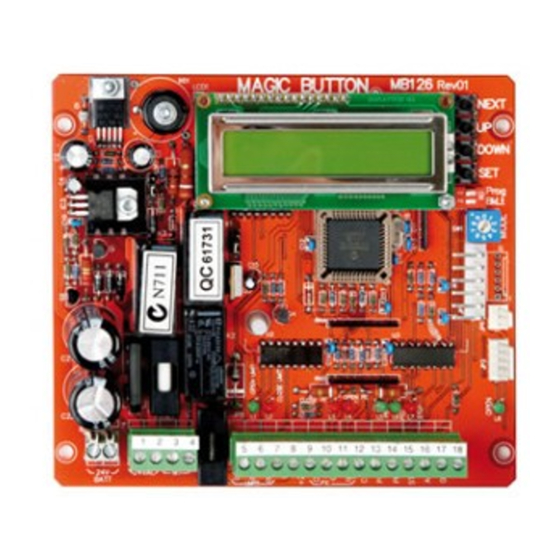
3
2
1
LNK2
3
2
1
LNK1
-
+
1
2
3
4
24V BA TT
Anleitungen und elektrische Installation CB224
de
Instructions et installation électrique CB224
fr
Instructions and electrical set up CB224
en
Instruktie en electrische installatie CB224
nl
Instrucciones y instalación eléctrica CB224
es
Email: info@chamberlain.de
LCD Display
1 2 3
LNK3
5
6
7
8
9 10 11 12 13 14 15 16 17 18
COM NO
www.liftmaster.de
1
2
6
1
Publicidad
Tabla de contenido

Manuales relacionados para Chamberlain LiftMaster Professional CB224


Resumen de contenidos para Chamberlain LiftMaster Professional CB224
- Página 1 9 10 11 12 13 14 15 16 17 18 COM NO 24V BA TT Anleitungen und elektrische Installation CB224 Instructions et installation électrique CB224 Instructions and electrical set up CB224 Instruktie en electrische installatie CB224 Instrucciones y instalación eléctrica CB224 www.liftmaster.de Email: info@chamberlain.de...
- Página 2 ACHTUNG WICHTIGE ANWEISUNGEN ZUR MONTAGE UND NUTZUNG BEGINNEN SIE MIT LESEN DIESER WICHTIGEN SICHERHEITSREGELN Solche Warnzeichen bedeuten “Vorsicht!”, eine Aufforderung zur Beachtung, da ihre Mißachtung Personen- bzw. Sachschäden verursachen kann. Bitte lesen Sie diese Warnungen sorgfältig. Dieser Torantrieb ist so konstruiert und geprüft, daß er bei Installation und Benutzung unter genauer Befolgung der anschließenden Sicherheitsregeln angemessene Sicherheit bietet.
- Página 3 230 - 24V TRANSFORMER 80 -150VA ANSCHLUSS DER KABEL FÜR DEN ENDSCHALTER Beschreibung für Antriebe Chamberlain mit Magnetendschaltern: Der korrekte Anschluss der Endschalter AUF / ZU ist wichtig für den Betrieb der Anlage. Ist die Einfahrt LINKS vom Antrieb dann:...
- Página 4 DREHSCHALTER FÜR PROGRAMME 0 - 9 SICHERUNGEN: F1 = 10A Sichert den Motor Position 1: Standard F2 = 1A Sichert Zubehör Klemme 8 + 9 Tor öffnet nach Signal und schließt am nächsten. Während des Öffnens stoppt das Tor zuerst und schließt erst am nächsten Signal. ANSCHLÜSSE: Unterbrechung der Lichtschranke während des Schließens reversiert das Tor komplett nach AUF.
- Página 5 Steckbrücken LNK („Jumper“, „Links“) Je nach Stellung der Steckbrücke können verschiedene Funktionen eingestellt werden. LNK1: (Nicht umstecken!) LNK2 1+2= (unten) Für 24Volt Trafo und Antrieb (Chamberlain Antriebe) LCD Display 2+3= (oben) Für 12Volt LNK2 LNK1 LNK2: (Nicht umstecken!) Backup Batterie...
- Página 6 TASTER / SCHLÜSSELSCHALTER (OPTIONAL) Die Steuerung / Antrieb kann mittels verschiedener Eingänge aktiviert werden. Dies kann mittels Handsender oder Schlüsselschalter 9 10 11 12 13 14 15 16 17 1 erfolgen (Klemmen 13-15). Handsender = siehe Punkt Einlernen der Handsender 13-14 = Input St.
- Página 7 FUNKADAPTER 801719-6 Um die Steuerung mittels Funk zu betreiben, muß vorher ein Funkmodul installiert werden. EINLERNEN / LÖSCHEN DER HANDSENDER Siehe Beschreibung Funkadapter RPM SENSOR Ein Drehzahlmesser (RPM Sensor) kann optional installiert werden. Der Sensor ermöglicht eine automatische Reversierung des Tores bei Hinderniserkennung. RPM Sensor: Stecker JP6 auf der Steuerung Wird eine Batterie verwendet, muß...
-
Página 8: Programmierung Der Steuerung
P8 = Open PE Type Lichtschranke Typvorwahl Lichtschranke: RLY - Relaislichtschranke RLY - PLS AUF - Richtung PLS - Pulse (Chamberlain Lichtschranke 770E und 771E) Def: RLY Now: RLY P9 = Close PE Type Lichtschranke Typvorwahl Lichtschranke: RLY - Relaislichtschranke... -
Página 9: Erste Fahrt
P8= Typ der Lichtschranke an Klemme 12 (AUF) einstellen RLY für „keine“ (dann ist eine Drahtbrücke erforderlich) und Relaislichtschranke oder PLS für Chamberlain Lichtschranke (2- Kabel Lichtschranke) P9= Typ der Lichtschranke an Klemme 11 (ZU) einstellen RLY für „keine“ (dann ist eine Drahtbrücke erforderlich) und Relaislichtschranke oder PLS für Chamberlain Lichtschranke (2- Kabel Lichtschranke) - Página 10 Die Installation einer Aussenantenne ist empfehlenswert, da sich die Steuerung mit der kurzen Kabelantenne in den meisten Fällen hinter dem Pfeiler oder in Bodennähe befindet. Die optimale Antennenposition ist immer so hoch wie möglich. Chamberlain bietet als Zubehör eine entsprechende Antenne mit Montagesatz unter der Bezeichnung ANT4X-1EML an.
- Página 11 ATTENTION INSTRUCTIONS IMPORTANTES POUR LE MONTAGE ET L’UTILISATION VEUILLEZ TOUT D'ABORD LIRE CES REGLES DE SECURITE IMPORTANTES Ces pictogrammes appellent à la prudence et ont valeur d'avertissement, car leur non-respect peut entraîner un risque de blessures corporelles ou de dommages matériels. Veuillez lire attentivement ces avertissements.
- Página 12 80 -150VA RACCORDEMENT DES CABLES POUR LE CONTACTEUR DE FIN DE COURSE Description des entraînements Chamberlain avec contacteurs de fin de course magnétiques : Le raccordement correct OUVERT / FERME des contacteurs de fin de course est important pour l’utilisation de l’installation.
-
Página 13: Batterie De Secours (Optionnelle)
FUSIBLES : COMMUTATEUR ROTATIF POUR LES PROGRAMMES 0 - 9 Position 1 : standard F1 = 10A Protège le moteur La porte s’ouvre après un signal et se ferme au prochain signal. F2 = 1A Protège les accessoires bornes 8 + 9 Durant l’ouverture, la porte s’arrête d’abord, et ne se ferme qu’à... - Página 14 (voir description) Si la fonction „Fermeture automatique“ est souhaitée, il faut installer la barrière photoélectrique à sécurité intégrée Chamberlain. Le système à sûreté intégré Chamberlain (système à 2 câbles) possède des deux côtés une petite DEL visible de l’extérieur (lumière) pour indiquer l’état de la barrière close/schliessen/fermer/sluiten photoélectrique.
- Página 15 BOUTON-POUSSOIR / INTERRUPTEUR A CLE (OPTION) La commande / l’entraînement peut être activé au moyen de différentes entrées. Ceci peut être fait par un émetteurl ou un 9 10 11 12 13 14 15 16 17 1 interrupteur à clé (bornes 13-15). Emetteur = voir le point apprentissage de l’émetteur 13-14 = Input St.
- Página 16 MODULE RADIO 801719-6 Pour pouvoir faire fonctionner la commande par radio (télécommande), il faut d’abord installer un module radio. PROGRAMMATION / EFFACEMENT DES EMETTEURS Voir description de l’adaptateur radio CAPTEUR RPM Un capteur de régime (capteur RPM) peut être installé en option. Le capteur permet d’inverser automatiquement le portail en cas de détection d’obstacle.
-
Página 17: Programmation De La Commande
« NO » Non Paramètres propres Sélection P1= Motor Type Sélection du moteur utilisé: 0= aucun moteur 1= Chamberlain/Liftmaster Type de moteur 0 - 3 Def: 0 Now: 0 Pour tout autre moteur, voir la description P2 = M1 Travel Time é... -
Página 18: Premiere Mise En Service/Reglages De Base
P6= démarrage lent préréglé à 0,5 secondes (selon souhaits) P8= régler le type de barrière photoélectrique au niveau de la borne 12 (OUVERT) ; RLY pour aucune (un pont en fil est alors nécessaire) et barrières photoélectriques à relais, ou PLS pour barrières photoélectriques Chamberlain (barrières photoélectriques bifilaires). - Página 19 Que se passe-il en cas de coupure de courant ? Tous les ouvre-portails Chamberlain disposent d'un dispositif de déverrouillage permettant de manoeuvrer le portail à la main en cas de coupure de courant. Est-il possible de n'ouvrir que partiellement le portail? Oui, c'est possible.
-
Página 20: Electrical Installation
ATTENTION IMPORTANT FITTING AND OPERATING INSTRUCTIONS PLEASE START BY READING THESE IMPORTANT SAFETY RULES • SAVE THESE INSTRUCTIONS This safety alert symbol means "Caution" - failure to comply with such an instruction involves risk of personal injury or damage to property. Please read these warnings carefully. This gate drive mechanism is designed and tested to offer appropriately safe service provided it is installed and operated in strict accordance with the following safety rules. - Página 21 TRANSFORMER 80 -150VA CONNECTION OF WIRES FOR LIMIT SWITCH Description for Chamberlain drives with magnetic limit switches: The correct installation of the limit switches UP / DOWN is important for the operation of the unit. If the entry is LEFT of the drive, then:...
- Página 22 FUSES: TURN-SWITCH FOR PROGRAMS 0-9 F1 = 10A secures the motor Position 1: Standard Gate opens after signal and closes with the next one. During opening F2 = 1A secures accessories terminals 8 + 9 sequence the gate first stops and closes and does not close until the next signal.
- Página 23 Settings: In menu P7 + P8 the control has to be set to the connected photo cells. For Chamberlain 2-wire photo cells the setting PLS = pulse is required. For relay-photo cells select setting RLY = relay. Diagnosis at the Chamberlain failsafe photocell...
- Página 24 PUSHBUTTON / KEY-OPERATED SWITCH (OPTIONAL) The control board / drive can be activated using various inputs. This can be done using a hand-held transmitter or key-operated 9 10 11 12 13 14 15 16 17 1 switch (terminals 13-15)). Hand-held transmitter = see Teaching the hand-held transmitter 13-14 = input control 1.
- Página 25 RADIO MODULE 801719-6 To operate the control board via radio remote control, a radio module must first be installed. TEACHING / DELETING THE HAND-HELD TRANSMITTERS See description radio adapter. RPM SENSOR A rotational speed sensor (RPM sensor) can be optionally installed. The sensor enables the automatic reversing of the gate if an obstacle is detected.
- Página 26 Preselection of photo cell type: RLY – relay photo cell P8 = Open PE Type photocell open- PLS – pulse (Chamberlain photo cell 770E and 771E) RLY - PLS Def: RLY Now: RLY direction Preselection of photo cell type: RLY – relay photo cell...
- Página 27 “standard”. Complete potential changes later (see description). 8. Turn switch to 1 (ON) and control/change the following menu settings: P1 = 1 Chamberlain LiftMaster Motor P4 = very lightweight gates PVC, aluminium should be operated with less force than is preset (50%).
- Página 28 What happens in case of power failure? All Chamberlain gate openers are equipped with a release system by means of which the gate can be operated manually in case of power failure.
-
Página 29: Elektrische Installatie
ATTENTIE BELANGRIJKE INSTRUCTIES VOOR MONTAGE EN GEBRUIK BEGIN MET HET LEZEN VAN DEZE BELANGRIJKE VEILIGHEIDSINSTRUCTIES! Deze waarschuwingstekens betekenen ”voorzichtig!” en zijn een aansporing om goed op te letten, omdat het veronachtzamen ervan lichamelijk letsel of materiële schade teweeg kan brengen. Lees deze instructies a.u.b. zorgvuldig. Deze hekaandrijving is zo geconstrueerd en gecontroleerd dat deze tijdens installatie en gebruik bij nauwkeurige naleving van de betreffende veiligheidsinstructies voldoende veilig is. - Página 30 230 - 24V TRANSFORMER 80 -150VA AANSLUITING VAN DE KABEL VOOR DE EINDSCHAKELAAR Beschrijving voor aandrijvingen Chamberlain met magneeteindschakelaars: De correcte aansluiting van de eindschakelaars OPEN / DICHT is belangrijk voor de werking van de installatie. Is de inrit LINKS van de aandrijving, dan is:...
- Página 31 ZEKERINGEN: DRAAISCHAKELAAR VOOR PROGRAMMA 0-9 F1 = 10A Beveiligt de motor Positie 1: Standaard De poort opent na het signaal en sluit bij het volgende. Tijdens het F2 = 1A Beveiligt accessoires klem 8 + 9 openen stopt de poort eerst en sluit pas bij het volgende signaal. Als AANSLUITINGEN: de foto-elektrische beveiliging tijdens het sluiten wordt onderbroken, keert de poort om in de OPEN richting.
- Página 32 In het menu P7 + P8 moet de besturing op de aangesloten foto- elektrische beveiliging worden ingesteld. Voor de Chamberlain foto-elektrische beveiliging met 2 kabels is de instelling PLS = Pulse te kiezen 9 10 11 12 13 14 15 16 17 18...
- Página 33 DRUKKNOP/SLEUTELSCHAKELAAR (OPTIONEEL) De besturing/aandrijving kan over verschillende ingangen geactiveerd worden. Dit kan met een handzender of sleutelschakelaar gedaan 9 10 11 12 13 14 15 16 17 1 worden (contacten13+15). Handzender = zie punt Aanleren van de handzender 13-14 = input besturing 1 Normaal gebruik 13-15 = input besturing 2 Actief bij speciale instellingen (zie beschrijving) Menu P12 + P13 NOODSTOP (OPTIONEEL) 600084...
- Página 34 RADIOMODULE (OPTIONEEL) Om de besturing via een radiografisch signaal te kunnen gebruiken, moet er eerst een radiomodule worden geïnstalleerd. AANLEREN / WISSEN VAN DE HANDZENDER Zie beschrijving draadloze adapter RPM-SENSOR Een toerentalmeter (RPM-sensor) kan optioneel geïnstalleerd worden. De sensor zorgt voor het automatisch teruggaan van het hek bij oplopen op een obstakel.
- Página 35 Def: 0 Now: 0.0s aangesloten fot.elektrische beveiliging. Foto-elektrische Typeselectie foto-elektrische beveiliging: RLY- foto-elektrische beveiliging P8 = Open PE Type Beveilging Open - met relais, PLS- Pulse (Chamberlain foto-elektrische beveiliging 770E en RLY - PLS Def: RLY Now: RLY richting 771E) Foto-elektrische...
-
Página 36: Eerste Gebruik
P6= Trage start vooraf ingesteld op 0,5 sec. (naar wens) P8= type foto-elektrische beveiliging op klem 12 (OPEN) instellen RLY voor „geen“ (dan is er een draadbrug nodig) en foto- elektrische beveiliging met relais of PLS voor Chamberlain fotoelektrische beveiliging (foto-elektrische beveiliging met 2 kabels) P9= type foto-elektrische beveiliging op klem 11 (DICHT) instellen RLY voor „geen“... - Página 37 De installatie van een buitenantenne wordt geadviseerd, omdat de besturing met de korte kabelantenne zich in de meeste gevallen achter de pijler of vlak bij de grond bevindt. De optimale antennepositie moet altijd zo hoog mogelijk zijn. Chamberlain biedt als toebehoren een bijbehorende antenne met montageset aan onder de omschrijving ANT4X-1EML.
-
Página 38: Antes De Comenzar, Lea Las Normas De Seguridad Que Resultan Fundamentales
PRECAUCIÓN INSTRUCCIONES IMPORTANTES PARA EL MONTAJE Y LA UTILIZACIÓN ANTES DE COMENZAR, LEA LAS NORMAS DE SEGURIDAD QUE RESULTAN FUNDAMENTALES Este símbolo de advertencia sobre seguridad indica "Precaución”. En caso de no cumplirse supondrá un riesgo de lesión personal o daño a la propiedad. Lea estas advertencias detenidamente. El mecanismo de apertura de la puerta se ha diseñado y probado con el fin de proporcionar un servicio adecuadamente seguro siempre y cuando sea instalado y operado ateniéndose estrictamente a las siguientes normas de seguridad. -
Página 39: Construcción Típica De Una Instalación
TRANSFORMER 80 -150VA CONEXIÓN DE LOS CABLES PARA EL INTERRUPTOR DE FIN DE CARRERA Descripción para accionamientos Chamberlain con interruptores de fin de carrera magnéticos: 9 10 11 1 COM NO La conexión correcta de los interruptores de fin de carrera ABIERTO/CERRADO es importante para el funcionamiento de la instalación. -
Página 40: Conexiones
FUSIBLES: INTERRUPTOR GIRATORIO PARA PROGRAMAS 0-9 F1 = 10A protege el motor Posición 1: Estándar La compuerta se abre después de la señal y se cierra en la F2 = 1A protege los accesorios borne 8+9 siguiente. Durante la abertura la compuerta se detiene en un primer momento y se cierra justo en la siguiente señal. - Página 41 En el menú P7 + P8 debe ajustarse el control a las barreras de luz conectadas. Para la barrera de luz Chamberlain de 2 cables debe seleccionarse el ajuste PLS = Pulse Para las barreras de luz de relés debe seleccionarse el ajuste RLY = Relé...
-
Página 42: Monitorización De La Puerta / Iluminación (Opcional)
TECLA / CERRADURA A LLAVE EXTERNA (OPCIONAL) El mando / accionamiento puede activarse con entradas diferentes. Esto se puede conseguir con ayuda de un telemando o una 9 10 11 12 13 14 15 16 17 1 cerradura a llave externa a llave (bornes 13-15). Telemando = véase punto de memorización del telemando 13-14 = Input St. -
Página 43: Memorización / Borrado Del Telemando
MÓDULO DE RADIO 801719-6 Para accionar el control por medio de la radio, debe instalarse antes un módulo de radio. MEMORIZACIÓN / BORRADO DEL TELEMANDO Véase la descripción del adaptador de radio SENSOR RPM Un cuentarrevoluciones (sensor RPM) puede instalarse opcionalmente. -
Página 44: Programación Del Control
“NO” Ajuste propio ó i ó i Selección Ajuste del motor utilizado: 0 = sin motor 1= Chamberlain/Liftmaster. P1= Motor Type Tipo de motor 0 - 3 Def: 0 Now: 0 Para otros véase la descripción. P2 = M1 Travel Time Def: 5 Now: 5.0s... -
Página 45: Primera Puesta En Marcha/Ajuste Básico
P8 = Ajuste del tipo de barrera de luz en el borne 12 (ABIERTO), RLY para “ninguna” (a continuación se necesita una unión de alambre) y barrera de luz de relé o PLS para barrera de luz Chamberlain (barrera de luz de 2 cables) P9 = Ajuste el tipo de barrera de luz en el borne 11 (CERRADO), RLY para “ninguna”... - Página 46 Se recomienda instalar una antena exterior ya que, con la antena de cable corta, el control se sitúa habitualmente detrás del pilar o cerca del suelo. La posición óptima de la antena es siempre la más alta posible. Entre sus accesorios, Chamberlain dispone de la antena correspondiente con un kit de montaje, cuya designación es ANT4X-1EML.
- Página 47 NOTES:...
- Página 48 709469B © Chamberlain GmbH, 2009...