Publicidad
Enlaces rápidos
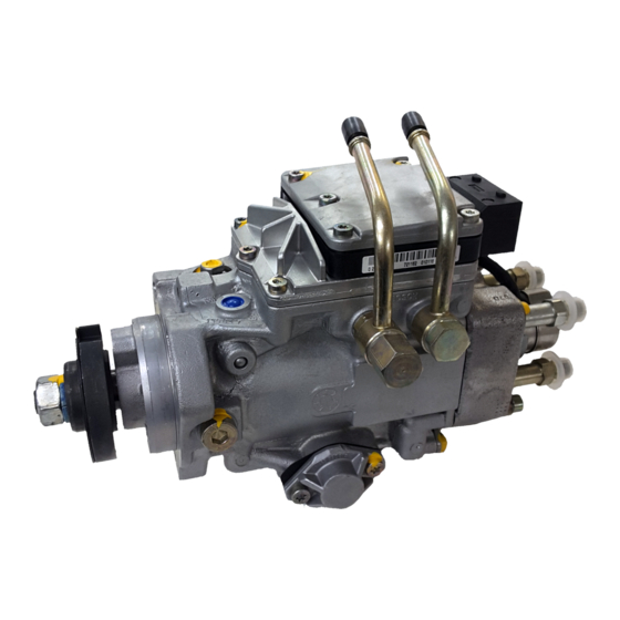
GF15364A
BOSCH VP44 Injection Pump
Instruction Sheet
Removal / Installation Procedures:
1. Disconnect both battery ground cables.
2. Thoroughly clean all fuel lines and fittings leading to the pump to
prevent contamination.
3. Disconnect the nine-way electrical connector at Fuel Pump Control Module (FPCM).
4. Remove the fuel supply line and return line (including the overflow valve).
WARNING: Before removing the pump, make sure the pump keyway is in the
12 o'clock position (See Figure 1). This will prevent it from falling into the gear
housing, and make installation easier as well. If necessary, the engine can be
rotated with a barring tool (Snap-On # SP371 or MTE # 3377371 Cummins
Tools). The barring tool port is located on the rear engine flange near the
exhaust manifold. Remove the rubber plug for access.
5. Remove all high-pressure fuel lines, the intake air tube, and all other
attaching components.
6. Remove the pump nut and washer. Be careful not to drop the gear retainer or nut into the
gear housing.
7. Use a gear puller to separate the pump gear from pump shaft using two M8 X 1.24 MM
screws through the puller and into the two threaded holes in the pump gear. Pull the injection
pump gear forward until it loosens from pump shaft. Only pull enough to loosen the gear. Pulling
the gear too far may cause damage to the gear cover.
8. Remove the two rear lower pump bracket bolts.
9. Remove the four injection pump to gear housing mounting nuts.
10. Remove the injection pump from gear housing, being careful not to nick or damage the
housing or pump shaft.
WARNING: When removing the pump from the engine take caution to not rotate the engine as it
can cause serious damage to the pump drive gear.
11. Clean the injection pump mounting flange and install a new O-ring. Coat the O-ring with
clean engine oil, but leave the housing dry.
12. Clean the pump gear and the new pump shaft taper with brake cleaner – surfaces must
remain oil-free and dry.
13. Install the new injection pump making sure the keyway is at the 12 o'clock position. (See
Figure 1). Align the pump flange hole with the pump housing index dowel. Make sure the pump
moves easily into the housing indicating the keyway is properly aligned. If it does not, recheck
the keyway alignment and try again.
14. Tighten the mounting bolts finger-tight initially and make sure the pump is flush with the
housing on all sides.
WARNING: Improper alignment of key is a common fault that may occur during installation.
In order to prevent it from occurring, follow these steps:
1. Do preliminary tightening of the pump shaft nut to 30 Nm (15-22 ft. lbs.)
(This is not the final torque).
2. Tighten the four pump mounting nuts to 43 Nm (32 ft. lbs.).
3. Tighten the two rear lower pump bracket to pump bolts to 24 Nm (18 ft. lbs.).
4. Do final tightening of the pump shaft nut to 170 Nm (125 ft. lbs.) torque.
Note: Use the barring tool to prevent engine from rotation.
15. Install the fuel supply line using new gaskets. Tighten the banjo bolts to 24 Nm (18 ft. lbs.).
16. Install the overflow valve (including return line) using new gaskets. Tighten the overflow
valve to 24 Nm (18 ft. lbs.).
17. Install all high-pressure fuel lines.
18. Connect the nine-way electrical connector to Fuel Pump Control Module.
19. Connect both negative ground battery cables.
20. Change the fuel filter and flush the lines and water separator to prevent contamination.
If you suspect contamination, flush the fuel tank and lines as well.
21. Bleed air from the fuel system. Refer to service manual for proper procedures.
22. Check the lift pump pressure by cranking the engine. The pressure should be between
8-10 PSI during cranking. If pressure is low, replace the lift pump.
WARNING: Low lift pump pressure can cause premature injection pump failure.
23. Start the engine and check the system for fuel or engine oil leaks.
IMPORTANT PRODUCT WARRANTY INFORMATION:
Warranty will be voided by the following.
Front
Devant
Pump Keyway
Frente
Rainure
RENSEIGNEMENTS IMPORTANTS SUR
de clavette
LA GARANTIE DU PRODUIT :
Ranura de
la bomba
Fig. 1
Les facteurs suivants invalident la garantie :
INFORMACIÓN IMPORTANTE SOBRE
LA GARANTÍA DEL PRODUCTO:
No se aplicará la garantía si se produce alguno
de los siguientes:
Pompe d'injection BOSCH VP44
Mode de dépose et d'installation :
1. Débrancher les deux câbles de masse de la batterie.
2. Nettoyer à fond toutes les canalisations et pièces de raccordement à la pompe afin de prévenir
la contamination.
3. Débrancher le connecteur électrique à neuf voies du module de commande de la pompe à
carburant (MCPC).
4. Enlever la canalisation d'alimentation en carburant et la canalisation de retour (y compris la
soupape de décharge).
AVERTISSEMENT : Avant d'enlever la pompe, s'assurer que la rainure de clavette se trouve à
12 h (voir figure 1) afin qu'elle ne tombe pas dans le carter d'engrenage, ainsi que pour faciliter
l'installation. Au besoin, faire pivoter le moteur au moyen d'un vireur (outils Snap On n o SP371 ou
MTE n o 3377371 -- Cummins Tool Division). L'orifice du vireur se trouve sur le flasque arrière du
moteur, près de la tubulure d'échappement. Retirer l'obturateur en caoutchouc pour y avoir accès.
5. Retirer toutes les canalisations de carburant sous haute pression, le tube d'admission d'air ainsi
que tous les autres composants de fixation.
6. Retirer l'écrou et la rondelle de la pompe. Prendre soin de ne pas faire tomber la pièce de
retenue ou l'écrou dans le carter d'engrenage.
7. Pour séparer l'arbre et l'engrenage de la pompe, utiliser un extracteur d'engrenage pour insérer
deux vis M8 x 1,24 mm dans les deux trous filetés de l'engrenage de la pompe. Tirer l'engrenage de
la pompe jusqu'à ce qu'il se dégage de l'arbre de la pompe. Tirer seulement suffisamment pour
desserrer l'engrenage. Tirer l'engrenage trop loin pourrait endommager le couvercle d'engrenage.
8. Enlever les deux boulons du support de pompe inférieur arrière.
9. Enlever les quatre écrous qui fixent la pompe au carter d'engrenage.
• Use of Aftermarket Performance Modules
• Use of Bio-Diesel Fuel
• Damaged pump shafts or keyways due
to improper installation
• Utilisation de modules de performance
de rechange
• Utilisation de biodiesel
• Arbres ou rainures de clavette
de pompe endommagés en raison
d'une installation incorrecte.
• Uso de módulos de desempeño del mercado
secundario de repuestos
• Uso de combustible biodiesel
• Daños en el vástago o en la ranura de la
bomba o ranuras dañados por una
instalación incorrecta.
Fiche d'instructions
Publicidad

Manuales relacionados para Bosch VP44


Resumen de contenidos para Bosch VP44
- Página 1 GF15364A BOSCH VP44 Injection Pump Instruction Sheet Removal / Installation Procedures: IMPORTANT PRODUCT WARRANTY INFORMATION: 1. Disconnect both battery ground cables. Warranty will be voided by the following. 2. Thoroughly clean all fuel lines and fittings leading to the pump to •...
- Página 2 Hoja de instrucciones 17. Instale todas las líneas de combustible de alta presión. Bomba de inyección BOSCH VP44 18. Conecte el conector eléctrico de nueve vías al módulo de control de la bomba de combustible. 19. Conecte los dos cables de puesta a tierra de la batería.