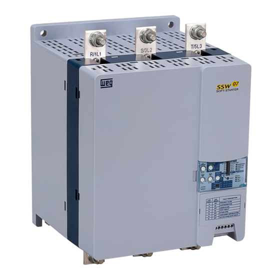
WEG SSW07 Guia De Inicio Rapido
Ocultar thumbs
Ver también para SSW07:
- Manual del usuario (162 páginas) ,
- Manual de la comunicación (31 páginas) ,
- Manual de comunicación (23 páginas)
Publicidad
Enlaces rápidos
Installation Guide
SSW07/SSW08/SSW900
IP20 Kit
1 DESCRIPTION OF THE KIT
Table 1.1: Contents of the Kit
SSW07/SSW08/SSW900 IP20 Kit
Quantity
Description
Size 3C
1
IP20 optional module
10935651
1
Installation guide
2 SAFETY NOTICES
DANGER!
Disconnect the power supply of the Soft-Starter SSW07/SSW08/SSW900
before installing the IP20 kit.
3 OPTIONAL MODULE DESCRIPTION
This optional module has the function to protect against contact to energized
parts.
The IP20 Kit is connected directly to the SSW07/SSW08/SSW900. The
module is fixed close to the power terminals, both at the line input and at
output to the motor.
4 IP20 KIT INSTALLATION PROCEDURE
1. Contents of the kit.
2. Snap the back cover at the holes located on both sides of the power
terminals.
3. Snap the front cover starting by the upper side.
English
11230435
4. Press it down until it fits into the back cover.
Size 4D
11059230
5. Check if the covers are fitted correctly.
6. Repeat the same process to fit the power supply covers.
Guía de Instalación
SSW07/SSW08/SSW900
Kit IP20
1 DESCRIPCIÓN DEL KIT
Tabla 1.1: Contenido del Kit
Kit IP20 del SSW07/SSW08/SSW900
Cuantidad
Descripción
Mecánica 3C
Mecánica 4D
1
Módulo opcional IP20
10935651
1
Guía de instalación
2 INFORMACIONES DE SEGURIDAD
¡PELIGRO!
Desconectar el Arrancador Suave SSW07/SSW08/SSW900 de la red
eléctrica antes de instalar el kit IP20.
3 INSTALACIÓN MECÁNICA
Este módulo opcional tiene la función de protección al contacto en las
partes energizadas.
El Kit IP20 es conectado directamente al SSW07/SSW08/SSW900. El módulo
es encajado junto a los bornes de conexión de potencia tanto en la entrada
de la red de alimentación cuanto en la salida para el motor.
4 PROCEDIMIENTO PARA LA INSTALACIÓN DEL KIT IP20
1. Contenido del kit.
2. Encaje la protección trasera en los orificios ubicados al lado de los
terminales de conexión de potencia.
3. Encaje la protección delantera primeramente por la parte superior.
Español
4. Presione para bajo hasta encajar en la protección trasera.
11059230
5. Certifíquese que las protecciones están encajadas.
6. Para encajar las protecciones en los bornes de potencia de la red de
alimentación, repita la secuencia anterior.
Publicidad

Resumen de contenidos para WEG SSW07
- Página 1 5. Check if the covers are fitted correctly. 5. Certifíquese que las protecciones están encajadas. The IP20 Kit is connected directly to the SSW07/SSW08/SSW900. The El Kit IP20 es conectado directamente al SSW07/SSW08/SSW900. El módulo module is fixed close to the power terminals, both at the line input and at es encajado junto a los bornes de conexión de potencia tanto en la entrada...
- Página 2 5. Certifique-se que as proteções estejam encaixadas. O Kit IP20 é conectado diretamente à SSW07/SSW08/SSW900. O módulo é encaixado junto aos bornes de conexão de potência tanto na entrada da rede de alimentação quanto na saída para o motor.


