Publicidad
Enlaces rápidos
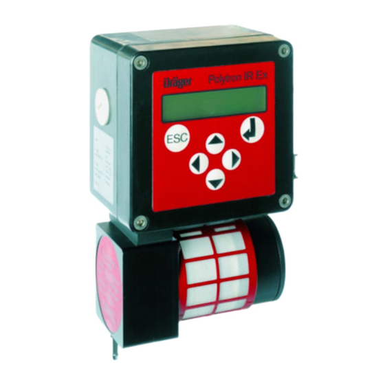
Polytron IR Transmitter Installation Instructions
Any use of the transmitter requires full understanding and strict observation of the
"Instructions for Use" of the Polytron Transmitter IR Ex (Part No. 90 23 655) or Polytron
Transmitter IR CO
/N
O (Part No. 90 23 656).
2
2
Installing Transmitter
The transmitter should always be mounted vertically (with the sensor pointing downwards) in a place where there is little vibration and minimum
changes of temperature, in the vicinity of a potential gas leak.
Secure in place by means of screws through the housing or use the mounting brackets (see drilling template). For maintenance purposes
allow at least 30 cm space below the transmitter.
When installing in explosion-hazard areas:
When wiring the transmitter to a central controller, the relevant regulations for the operation and installation of electrical equipment in
explosion-hazard areas must be observed (in Europe, EN 60079-14, in Germany VDE 0165).
Installing electrical connections
Connect to central controller by screened cable (braided screen cover ≥ 80 %, outside diameter max. 15 mm).
The 0 V conductor (terminals K2 and K3) should be grounded in the controller.
To ensure optimum electromagnetic compatibility (EMC):
— the transmitter should be grounded via one of the two grounding terminals. The screen should be connected to terminal E in the transmitter
and should not be grounded at the controller, or
— the transmitter is not grounded via the external terminals. The screen should be connected to terminal E in the transmitter and grounded at
the controller.
Three-wire type
Connect terminals K1 and K3 to the power supply (24 V ± 20 %,
300 mA).
Terminal K1 to + 24 V, terminal K3 to 0 V.
Connect terminal K4 to the 4 to 20 mA input of the central
controller.
K1
K3
K4
E
Connecting the display unit or IR junction box for the hand-held terminal to the NDF version:
Connect the transmitter (NDF version) terminals K11, K12 and K13 and E to terminals K1, K2 and K3 and E of the display unit or IR junction
box: K13 to K1, K11 to K2 and K12 to K3.
K13
K11
K12
K1 K2 K3
K1
K3
K2
IR junction box
The terminal cover (Ex-approved version) must be closed before starting up, otherwise the Ex-approval is invalid.
Technical Data (extract)
Measuring range:
Signal transmission to central
controller:
Supply voltage:
Cable entry:
For details and safety precautions refer to the "Instructions for Use" of the Polytron Transmitter IR Ex (Part No. 90 23 655) or Polytron
Transmitter IR CO
/N
O (Part No. 90 23 656).
2
2
90 23 654 - MA 4675.600 en/de/fr/es
© Dräger Safety AG & Co. KGaA
4th edition - May 2006
Subject to alteration
K1
K3
K4
E
optionally
Display unit
K3
E
K2
K1
E
according to sensor model
4 to 20 mA
24 V ±20 %, 300 mA
PG 13.5 for 6 mm to 12 mm
cable diameter
Four-wire type
Connect terminals K1 and K2 to the power supply (24 V ± 20 %,
300 mA).
Terminal K1 to + 24 V, terminal K2 to 0 V.
Connect terminals K3 and K4 to the central controller. Connect
terminal K4 to the 4 to 20 mA input and terminal K3 to 0 V.
K1
K2
K3
K4
E
K1
K3
K2
Power consumption:
Power consumption IR Ex CO
and IR Ex HC:
Protection type (EN 60 529):
Approval :
DMT 02 ATEX E 178 X
IECEx BVS 05.0007
Dräger Safety AG & Co. KGaA – Revalstraße 1, D-23560 Lübeck, Germany
Tel. +49 451 8 82 - 27 94 – Fax +49 451 8 82 - 49 91
D
terminal cover
K1
K2
E
K3
K4
E
E
K13
K11
K12
E
K12
K11 K13
Transmitter (NDF Version)
2
II 2G EEx me [ib] d IIB + H
Ex me [ib] d IIB + H
www.draeger.com
4 W
2 W
IP 65
0158
T4
2
T4
2
Publicidad

Resumen de contenidos para Dräger Polytron
- Página 1 IECEx BVS 05.0007 Ex me [ib] d IIB + H For details and safety precautions refer to the "Instructions for Use" of the Polytron Transmitter IR Ex (Part No. 90 23 655) or Polytron Transmitter IR CO O (Part No. 90 23 656).
-
Página 2: Technische Daten (Auszug)
II 2G EEx me [ib] d IIB + H IECEx BVS 05.0007 Ex me [ib] d IIB + H Weitere Informationen und Sicherheitsmaßnahmen entnehmen Sie der "Gebrauchsanweisung" des Polytron-Transmitters IR Ex (Sach-Nr. 90 23 655) oder des Polytron-Transmitters IR CO O (Sach-Nr. 90 23 656). - Página 3 IECEx BVS 05.0007 Ex me [ib] d IIB + H Vous trouverez d'autres informations et mesures de sécurité dans les "Instructions de service" du transmetteur Polytron IR Ex (N de réf. 90 23 655) ou du transmetteur Polytron IR CO O (N de réf.
- Página 4 IECEx BVS 05.0007 Ex me [ib] d IIB + H Más informaciones y medidas de seguridad se pueden encontrar en las "Instrucciones de uso" del Transmisor Polytron IR Ex (Nro de referencia. 90 23 655) o del Transmisor Polytron IR CO O (Nro de referencia.
- Página 5 Transmitter IR Ex drilling template / Bohrbild Transmitter IR Ex / Gabarit de perçage pour le transmetteur IR Ex / Plantilla de taladro transmisor IR Ex 106 mm / 4.17 Inch...
- Página 6 Transmitter IR Ex IL drilling template / Bohrbild Transmitter IR Ex IL / Gabarit de perçage pour le transmetteur IR Ex IL / Plantilla de taladro transmisor IR Ex IL 154 mm / 6.06 Inch...
- Página 7 Display unit drilling template / Bohrbild Anzeigeeinheit / Gabarit de perçage pour l'afficheur / Plantilla de taladro unidad de indicación 106 mm / 4.17 Inch...
- Página 8 IR junction box drilling template / Bohrbild Anschlussbox / Gabarit de perçage pour la boîte de jonction / Plantilla de taladro caja de conexión 68 mm / 2.68 Inch...


