Publicidad
Idiomas disponibles
Idiomas disponibles
Enlaces rápidos
NOTE: This equipment has been tested and found to com-
ply with the limits for a Class B digital device, pursuant to Part
15 of the FCC Rules. These limits are designed to provide
reasonable protection against harmful interference in a residential instal-
lation.
This equipment generates, uses and can radiate radio frequency energy
and, if not installed and used in accordance with the instructions, may
cause harmful interference to radio communications. However, there is
no guarantee that interference will not occur in a particular installation.
If this equipment does cause harmful interference to radio or television
reception, which can be determined by turning the equipment off and
on, the user is encouraged to try to correct the interference by one or
more of the following measures:
- Reorient or relocate the receiving antenna.
- Increase the separation between the equipment and receiver.
- Connect the equipment into an outlet on a circuit different from that to
which the receiver is connected.
- Consult the dealer or an experienced radio/TV technician for help.
A
L
N
DIMENSIONS IN MILLIMETRES
DIMENSIONES EN MILIMETROS
03.2009/2407-2101
C
B
+ −
+ −
B
L
A
CNV
LED SERVICE
A
210
43,5
7,5
57
B
210
64,5
XA/300LR US
R4
BPT S.p.A.
Via Cornia, 1
33079 Sesto al Reghena-PN-Italy
info@bpt.it – www.bpt.it
INSTALLATION
EN
INSTRUCTIONS
RJ45
POWER SUPPLIER
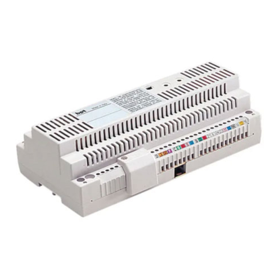
XA/300LR
Power supply and control unit, with
ECHELON bus, enables standard and
residential system 300 installations to
be created.
Enables conversations between entry
panels, receivers and porter switch-
board.
It manages service controls (entry panel
self-connection/selection,
release, stair light, auxiliary control/por-
ter call) as well as the engaged status.
For data lines to the block's entry
CNS
panels and/or main entrance panels,
SW2
the unit communicates by means of
the LON TALK protocol, whilst it uses a
1
BPT X2 TECHNOLOGY protocol
towards the receivers.
The bus connection towards the entry
panels consists of 3 twisted pairs plus
the power supply, whilst it uses a sin-
gle twisted pair plus power supply
towards the receivers.
The unit features a CNV connector for
connection to the XAV/300 video
modulator and a CNS connector for
connection to the ICB/300 selector.
The system 300 can be programmed
in either of two ways:
• Standard mode (installation with a
single XA/300LR power supplier) by
means of the actual XA/300LR sup-
plier;
• Extended mode (installation with a
number of XA/300LR power suppliers,
or if the standard configuration is to be
extended) by means of a PCS/300 or
MPP/300LR unit.
2
SYSTEM SETUP
WITH STANDARD MODE
PROGRAMMING
AND DEFAULT SETTINGS
System setup
1 - Maximum number of XA/300LR: 1.
2 - Maximum number of X2 blocks: 64.
3 - Maximum number of entry panels
per X2 block: 4.
4 - Maximum number of system 300
entry panels (19 with IPD/300LR).
5 - Maximum number of IPD/300LR
porter switchboards: 1.
6 - Maximum number of users con-
nected directly on XA/300LR: 100 (0 if
X2 blocks are present).
7 - Maximum number of users for X2
block: 100 (99 with IPD/300LR porter
switchboard).
8 - Maximum number of IOD/303LR
3
relay actuators: 1.
Default settings
1 - System activation time: call 30 s,
conversation max 60 s.
2 - Door-lock release activation time:
- for the system 300 entry panel (with
ICP/LR)
with
pushbuttons,
options are: 1 s, 4 s, 8 s and 16 s;
- for the HAC/300LR entry panel: adju-
stable from 1 s to 255 s;
- for the X2 entry panel: adjustable
from 1 s to 15 s;
3 - Aux. 1 control and door-lock relea-
se only enabled when receiver is cal-
led.
4 - Self-connection
between entry panels for X2 block
panels only.
5 - First key on all system 300 and X2
entry panels allocated automatically as
porter call key.
SYSTEM FEATURES
WITH EXTENDED MODE
PROGRAMMING
In this mode, system features can be
extended to enable more complex,
flexible and customizable solutions.
Below are just some of the options:
- extending the number of entry panels
and receivers per block;
- personalizzazione tempo di attivazio-
ne impianto e durata chiamata;
- programming all receivers using a
programmer (in this case, you will need
to collect the ID codes and enter them
in the tables that come with the pro-
door-lock
gramming devices);
- texts can be customized for naming
entry panels and users.
STANDARD
PROGRAMMING
Programming structures the system by
allocating a unique identification code
to all LON units (for example, ICP/LR,
HAC/300LR, IPD/300LR) and X2 units
(for example, receivers and X2 block
entry panels such as HEV/301,
HEC/301, etc.).
Programming is divided into two parts:
- receivers programming
- entry panels and accessories pro-
gramming.
ENTERING AND EXITING
STANDARD PROGRAMMING
To gain access to programming, it is
necessary to press the SERVICE but-
ton.
You can access programming by pro-
ceeding as follows.
1 - Programming receivers.
Press the SERVICE button for at least 3
s;
the yellow LED flashes at regular inter-
vals.
2 - Programming entry panels.
Press the SERVICE button again for
another 3 s;
the yellow LED stays on.
3 - Exiting programming and auto-
matic programming of IPD/300LR
and IOD/300LR units, where applica-
ble.
Lastly, press the SERVICE button for
approx. 1 s;
the yellow LED goes off.
PROGRAMMING
Power up the XA/300LR unit and pro-
ceed as follows.
WARNING. If the installation featu-
res more than one system 300
entry panel (ICP/LR o HAC/300LR),
or if you are dealing with an X2
time
and
switching
1
Publicidad

Manuales relacionados para Bpt XA/300LR US R4


Resumen de contenidos para Bpt XA/300LR US R4
- Página 1 PROGRAMMING the LON TALK protocol, whilst it uses a Programming structures the system by BPT X2 TECHNOLOGY protocol allocating a unique identification code towards the receivers. DIMENSIONS IN MILLIMETRES to all LON units (for example, ICP/LR,...
- Página 2 block-type installation, program all 2.3 - Repeat the procedure in 2.2 for RESIDENTIAL INSTALLATION WITH X2 BLOCKS entry panels first. the remaining entry panels (in the order If there is an IPD/300LR porter in which the entry panels are to be switchboard IOD/303LR scanned).
- Página 3 SLAVE X2 The LED goes off. ENTRY PANELS This procedure must be performed Contact BPT’s Technical Support for once you have programmed the units information on using this facility. described in point 2. 4.1 - Start with the block’s Master FUNCTION OF YELLOW LED entry panel.
- Página 4 4 - Autoactivación y exploración sólo hacia los derivados internos utiliza un otros 3 s; activated by the same call: 3 (8 with protocolo BPT X2 TECHNOLOGY. en placas exteriores de bloque X2. el LED amarillo queda encendido. at least 6 receivers with attenuated El bus de conexión hacia las placas...
-
Página 5: Para La Definición De Cada Placa Exterior De Bloque X2 Master Son
cionando cualquier placa exterior 300 A - Identificación placa exterior de INSTALACIÓN RESIDENCIAL CON BLOQUES X2 o la eventual centralita IPD/300LR bloque. (ver capítulo 5-MODIFICACIÓN B - Definición número llamadas DISPOSITIVO DE PROGRAMACIÓN usuarios del bloque. USUARIOS POR DEFECTO). Bloque X2 - 2 A - Identificación Si se elige la programación de los placa exterior de bloque... - Página 6 Wait for audible confirmation (*). una espera entre 3 s y 15 s aproxima- 2 - Pulsar de nuevo el botón de llama- con el Servicio Técnico de BPT. damente). da n. 10 (posición 2E) para definir el EJEMPLO 3 - Bloque X2 con placa 4.4 - Conectar de nuevo el puente...
- Página 7 Toma RJ45 (fig. 1) Esta toma permite la conexión con el dispositivo programación (IPC/300LR ó MPP/300LR). Características técnicas • Alimentación: 120/127 VAC 50/60 Hz. El aparato está protegido electróni- camente contra sobrecargas y cor- tocircuitos. • Absorción: 0.8 A. • Potencia disipada: 6 W máx. (pro- porcionar una ventilación adecuada si se instala el aparato en un conte- nedor).
- Página 8 INSTALLATION WIRING DIAGRAMS AUDIO ENTRY CONTROL pag. 11 ÷ 15 VIDEO ENTRY CONTROL pag. 16 ÷ 31 ESQUEMAS DE INSTALACION AUDIOINTERCOMUNICACION pag. 11 ÷ 15 VIDEOINTERCOMUNICACION pag. 16 ÷ 31 Cross-section of the supply line wires. Sección de los conductores de la línea de alimentación.
- Página 9 Fig.11 Colour coding of wires relating to CN2-CN3 wiring for connecting interface HIA/300 to the units installed in front plates HPV/1 and HPC/1. WARNING. Which wire is used for connection will depend on the num- ber of buttons installed. Fig.11 Color de los conductores correspondientes a los cableados CN2-CN3 para las conexiones de la...
- Página 10 Fig.12-13 Connection diagram of auxiliary door-lock release button (AE). Fig.12-13 Esquema de conexión del ICP/LR pulsador auxiliar abrepuerta (AE). MC/304 MC/304 ICP/LR...
- Página 11 SE 300C04. MULTI-FLAT AUDIO ENTRY INSTAL- NC/321 LATION WITH 1 ENTRANCE EQUIPO DE AUDIOINTERCOMUNI- CACION MULTIFAMILIAR CON 1 ENTRADA. XC/300 YC/300 (YC/300A) HPC/1+HA/200+ HIA/300+ICP/LR+ …KHPS (…KHPD)+ HTS+…HEP/306 (…HEP/312D) ICP/LR HIA/300 HEP/306 (HEP/312D) V OUT V IN XA/300LR 0 1 2 3 4 HA/200 CP: Personal door-bell button.
- Página 12 SE 300C02. SE 300C02. -A UL MULTI-FLAT AUDIO ENTRY INSTAL- LATION WITH 2 ENTRANCES. EQUIPO DE AUDIOINTERCOMUNI- CACION MULTIFAMILIAR CON 2 NC/321 ENTRADAS. XC/300 YC/300 (YC/300A) XC/300 YC/300 (YC/300A) CP: Personal door-bell button. Pulsador de llamada desde el rellano. SE 300C02. -B UL...
- Página 13 SE 300C02. -B UL SE 300C02. -A UL HPC/1+HA/200+ HIA/300+ICP/LR+ …KHPS (…KHPD)+ HTS+KHSO+ …HEP/306 (…HEP/312D) ICP/LR HIA/300 HEP/306 (HEP/312D) V OUT V IN 0 1 2 3 4 HA/200 KHSO XA/300LR TMP/…+TTS/…+ ICP/LR+MVA/300+ … MC/304 ICP/LR MVA/300 MC/304 MC/304...
- Página 14 SE 300C03. SE 300C03. -A UL MULTI-FLAT AUDIO ENTRY INSTAL- LATION WITH 3 ENTRANCES. EQUIPO DE AUDIOINTERCOMUNI- CACION MULTIFAMILIAR CON 3 NC/321 ENTRADAS. XC/300 YC/300 (YC/300A) XC/300 YC/300 (YC/300A) CP: Personal door-bell button. Pulsador de llamada desde el rellano. SE 300C03. -B UL...
- Página 15 SE 300C03. -B UL SE 300C03. -A UL HPC/1+HA/200+ HIA/300+ICP/LR+ …KHPS (…KHPD)+ HTS+KHSO+ …HEP/306 (…HEP/312D) ICP/LR HIA/300 HEP/306 (HEP/312D) V OUT V IN 0 1 2 3 4 HA/200 KHSO XA/300LR TMP/…+ TTS/…+ ICP/LR+ HAC/300LR+ MVA/300+ HPC/1+HA/200+ … MC/304 2HTS+HIA/300 HAC/300LR ICP/LR HIA/300...
- Página 16 SE 300V04. SE 300V04. -A UL MULTI-FLAT VIDEO ENTRY INSTAL- XV/200+XKP/300+ XC/300+XKP/85 LATION USING A CAMERA SEPARA- TED FROM THE ENTRY PANEL (CEN- TRALIZED VIDEO HANDSETS POWER SUPPLY). EQUIPO DE VIDEOINTERCOMUNI- CACION ELECTRONICO MULTIFAMI- LIAR CON TELECAMARA SEPARADA DE LA PLACA EXTERIOR (ALIMENTA- XC XT XC/300 CION...
- Página 17 SE 300V04. -B UL SE 300V04. -A UL XV/200+XKP/300+ XC/300+XKP/85 XC XT XC/300 YVM/300 XDV/304 NVM/300+NC/321 YKP/300+YV CP: Personal door-bell button. Pulsador de llamada desde el rellano. SE 300V04. -C UL...
- Página 18 SE 300V04. -C UL SE 300V04. -B UL 2x56 XAV/300 XA/300LR HPC/1+HA/200+ HIA/300+ICP/LR+ …KHPS (…KHPD)+ HTS+…HEP/306 (…HEP/312D) ICP/LR VLS/101 HIA/300 HEP/306 (HEP/312D) V OUT V IN 2x56 0 1 2 3 4 HA/200...
- Página 19 SE 300V05. SE 300V05. -A UL MULTI-FLAT VIDEO ENTRY INSTAL- LATION WITH 1 ENTRANCE (CEN- XV/200+XKP/300+ XC/300+XKP/85 TRALIZED VIDEO HANDSETS POWER SUPPLY). EQUIPO DE VIDEOINTERCOMUNI- CACION MULTIFAMILIAR CON 1 ENTRADA (ALIMENTACION CENTRA- LIZADA DE LOS VIDEOINTERCOMU- NICACIONS). XC XT XC/300 YVM/300 XDV/304 NVM/300+NC/321...
- Página 20 SE 300V05. -B UL SE 300V05. -A UL XV/200+XKP/300+ XC/300+XKP/85 XC XT XC/300 YVM/300 XDV/304 NVM/300+NC/321 YKP/300+YV CP: Personal door-bell button. Pulsador de llamada desde el rellano. SE 300V05. -C UL...