Tabla de contenido
Publicidad
Idiomas disponibles
Idiomas disponibles
Enlaces rápidos
CANADA
UNITED STATES
With your inspiring rating, COSTWAY will be more consistent to offer you EASY
SHOPPING EXPERIENCE, GOOD PRODUCTS and EFFICIENT SERVICE!
Mit Ihrer inspirierenden Bewertung wird COSTWAY konsistenter sein, um Ihnen
EIN SCHÖNES EINKAUFSERLEBNIS, GUTE PRODUKTE und EFFIZIENTEN
SERVICE zu bieten!
Avec votre évaluation inspirante, COSTWAY continuera à fournir une
EXPÉRIENCE D'ACHAT PRATIQUE, des PRODUITS DE QUALITÉ et un
SERVICE EFFICACE !
Con su calificación inspiradora, COSTWAY será más consistente para ofrecerle
EXPERIENCIA DE COMPRA FÁCIL, BUENOS PRODUCTOS y SERVICIO
EFICIENTE.
Con la tua valutazione incoraggiante, COSTWAY sarà più coerente per offrirti
ESPERIENZA DI ACQUISTO FACILE, BUONI PRODOTTI e SERVIZIO
EFFICIENTE!
Dzięki twojej opinii COSTWAY będzie mógł oferować jeszcze WYGODNIEJSZE
ZAKUPY, LEPSZE PRODUKTY i SPRAWNIEJSZĄ OBSŁUGĘ KLIENTA.
US office: Fontana
UK office: Ipswich
DE office: FDS GmbH, Neuer Höltigbaum 36, 22143 Hamburg, Deutschland
FR office : 26 RUE DU VERTUQUET, 59960 NEUVILLE EN FERRAIN, FRANCE
UNITED KINGDOM
GERMANY
FRANCE
ITALY
SPAIN
RUSSIA
JAPAN
AUSTRALIA
Publicidad
Tabla de contenido

Manuales relacionados para Costway SP37675

Resumen de contenidos para Costway SP37675
- Página 1 JAPAN SPAIN AUSTRALIA With your inspiring rating, COSTWAY will be more consistent to offer you EASY SHOPPING EXPERIENCE, GOOD PRODUCTS and EFFICIENT SERVICE! Mit Ihrer inspirierenden Bewertung wird COSTWAY konsistenter sein, um Ihnen EIN SCHÖNES EINKAUFSERLEBNIS, GUTE PRODUKTE und EFFIZIENTEN SERVICE zu bieten! Avec votre évaluation inspirante, COSTWAY continuera à...
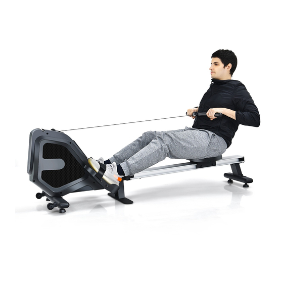
- Página 2 USER'S MANUAL/HANDBUCH/MANUEL DE L'UTILISATEUR /MANUAL DEL USUARIO/MANUALE UTENTE/INSTRUKCJA OBSŁUGI Rowing Machine / Rudergerät / Rameur / Máquina de Remo / Vogatore / Wioślarz SP37675...
- Página 3 IMPORTANT: Read all instructions carefully before using this product.Retain this owner's manual for future reference. The specifications of this product may vary from this photo, subject to change without notice. IMPORTANT SAFETY GUIDELINES Thank you for choosing our products. For your safety and health, please use this equipment correctly.
- Página 4 6. Be sure to use the equipment as instructed. If defective parts are found during assembly or inspection of equipment, or abnormal noise is heard during operation, the equipment shall be stopped immediately and reused after the problem is solved. 7.
- Página 5 HARDWARE & TOOLS PACK...
- Página 6 PRE-INSTALLED PARTS...
-
Página 7: Overview Drawing
OVERVIEW DRAWING... - Página 8 Description Specification Frame assembly JTR101 Front leg assembly Spraying plastic /black Flat gasket Φ10*Φ20*1.6 Spring washer Φ10 Socket head cap screw M10*60 Frame connecting seat Spraying plastic /black Aluminium rail Anodic oxidation Rear foot base Spraying plastic /black Pedal plate Spraying plastic /black Rear leg assembly Spraying plastic /black...
- Página 9 Description Specification Outer hexagonal lock nut M10 Outer hexagon screw M10*100 Lock pin Φ10*100 Locking knob M12*55 Pedal(L) Pedal(R) Pedal fixed shaft Φ12.5*418 Outer hexagonal screw M8*20...
- Página 10 ASSEMBLY STEP 1 Connect the main frame assembly (1) with the front leg assembly (2), and fix them together with the socket head cap screw (5) and the flat gasket (3) and the spring washer (4). Fix the pedal plate (9) and the frame assembly (1) together with the hexagon socket countersunk head screw (18).
- Página 11 STEP 2 Place the rear leg assembly (10) under the semicircular piece of the rear foot base(8), and then fix it with the cap nut (19) and flat gasket (3). Place the rear foot base 8# under the aluminum rail, and then fix it with the hexagon socket flat head screws(13), the flat gasket(11) and the spring washer(12).
- Página 12 STEP 3 Put the seat cushion assembly (20) on the end of the slide rail and put it in the aluminum rail (7). Insert the frame connecting seat(6) into the slide rail, and fix it with hexagon socket flat head screws(13), spring washer(12) and flat gasket(11).
- Página 13 STEP 4 Connect the main frame assembly (1) with the aluminum rail (7), and fix them with the outer hexagonal lock nut (21), flat gasket (3) and outer hexagon screw (22). Insert the lock pin (23) Screw the locking knob (24) into the nut from above, making sure that it is tightened in place.
- Página 14 STEP 5 Pass the pedal fixed shaft (27) through the hole. Insert the pedals (25 & 26) into the shaft, and then fix it with the outer hexagonal screw (28) and the flat gasket (11).
- Página 15 FOLDING INSTRUCTIONS Step 1 Unscrew the locking knob (24) first, and then pull out the lock pin (23) from its position.
- Página 16 Step 2 Lift the aluminum rail slowly to make it stand upright, and then insert the lock pin (23) into the hole. Adjust the length position of the nut on the locking knob (24), and then turn it back to the corresponding position. At this time, the equipment is folded successfully.
- Página 17 ELECTRONIC METER Rowing Machine Operating Instructions 1. Function ★ Functions: timer, 500 meters/min, count, distance, calories, strokes/min. 2. Key Key Name Function MODE Modes switching Increase in setting value RESET Set value cleared to 0 3. Operation Function 1) Power on When power on, the LCD will display for 1 second, and the buzzer will sound "BI"...
- Página 18 SET Key: When switching to the corresponding setting mode, press the UP key to increase the setting value. Press and hold for 2 seconds, it will increase quickly (change 5 times per second). It is invalid to press the UP key when not in the setting mode. RESET Key When switching to the corresponding setting mode, press the RESET key to clear the current value.
- Página 19 6) Distance (DIST) Measure the distance from the beginning of the exercise to the stop of the exercise. Measuring range: 0.0~99.9KM (ML), return to zero after single item overflow. 7) Calories (CAL) Measure the calories (CAL) consumed from the start of the exercise to the stop of the exercise.
- Página 20 4.Battery This monitor uses 2 batteries If the display screen is displayed incorrectly, reinstall the battery, and the effect will be better. When replacing the battery, all records will be deleted. To replace the battery, press the button at the bottom of the LED box to open the cover(See Figure 1), then press the button in the back to open the battery case (see Figure 2), and you can change the battery now.
- Página 21 Pull the button Figure 2 * Important Safety Information * Please observe the following safety rules to avoid injury and/or accidents. 1. Keep the rowing machine away from children, and do not let children around when using the rowing machine. 2.
- Página 22 WICHTIG: Lesen Sie alle Anweisungen sorgfältig durch, bevor Sie dieses Produkt verwenden. Bewahren Sie dieses Benutzerhandbuch zum späteren Nachschlagen auf. Die technischen Daten dieses Produkts können von diesem Foto abweichen, Änderungen sind vorbehalten. WICHTIGE SICHERHEITSRICHTLINIEN Vielen Dank, dass Sie sich für unsere Produkte entschieden haben. Bitte verwenden Sie dieses Gerät zu Ihrer Sicherheit und Gesundheit korrekt.
- Página 23 5.Vergewissern Sie sich vor der Verwendung des Geräts, dass alle Muttern und Schrauben fest angezogen sind. Nur durch regelmäßige Kontrolle der Beschädigung und/oder des Verschleißes der Geräte kann die Sicherheit der Geräte aufrechterhalten werden. 6. Achten Sie darauf, dass Sie das Gerät gemäß den Anweisungen verwenden.
- Página 24 HARDWARE- & WERKZEUGPAKET...
- Página 25 VORINSTALLIERTE TEILE...
- Página 26 ÜBERSICHTSZEICHNUNG...
- Página 27 Beschreibung Spezifikation Menge Rahmenmontage JTR101 Vordere Beinbaugruppe Sprühplastik/ schwarz Flachdichtung Φ10*Φ20*1,6 Federscheibe Φ10 Zylinderschraube mit M10*60 Innensechskant Rahmenverbindungssitz Sprühplastik/ schwarz Aluminiumschiene Anodische Oxidierung Hinterer Fußsockel Sprühplastik/ schwarz Pedalplatte Sprühplastik/ schwarz Hintere Beinbaugruppe Sprühplastik/ schwarz Flachdichtung Φ8*Φ16*1,6 Federscheibe Φ8/ Stahl Flachkopfschrauben M8*20/ schwarz mit Innensechskant Frontabdeckung für...
- Página 28 Beschreibung Spezifikation Menge Äußere Sechskant-Sicherungsmutter Äußere M10*100 Sechskantschraube Sicherungsstift Φ10*100 Verriegelungsknopf M12*55 Pedal(L) Pedal(R) Sicherungsstift für Φ12,5*418 Pedal Äußere M8*20 Sechskantschraube...
- Página 29 MONTAGE SCHRITT 1 Verbinden Sie die Hauptrahmenbaugruppe (1) mit der vorderen Beinbaugruppe (2) und befestigen Sie sie mit der Innensechskantschraube (5) und der Flachdichtung (3) und der Federscheibe (4). Befestigen Sie die Pedalplatte (9) und die Rahmenbaugruppe (1) zusammen mit der Innensechskant- Senkkopfschraube (18).
- Página 30 SCHRITT 2 Legen Sie die hintere Beinbaugruppe (10) unter das halbrunde Stück der hinteren Fußbasis (8) und befestigen Sie sie dann mit der Hutmutter (19) und der Flachdichtung (3). Legen Sie den hinteren Fußsockel 8# unter die Aluminiumschiene und befestigen Sie ihn dann mit den Innensechskant-Flachkopfschrauben (13), der Flachdichtung (11) und der Federscheibe (12).
- Página 31 SCHRITT 3 Stecken Sie die Sitzkissen-Baugruppe (20) auf das Ende der Gleitschiene und legen Sie sie in die Aluminiumschiene (7). Setzen Sie den Rahmenverbindungssitz(6) in die Gleitschiene ein und befestigen Sie ihn mit Innensechskant-Flachkopfschrauben(13), Federscheibe(12) und Flachdichtung(11). Führen Sie die Befestigungswelle(15) in die Aluminiumschiene ein, setzen Sie beidseitig den Sperrstopfen(16) ein und sichern Sie ihn mit der Kreuzschlitz-Senkkopfschraube(17) auf beiden Seiten.
- Página 32 SCHRITT 4 Verbinden Sie die Hauptrahmenbaugruppe (1) mit der Aluminiumschiene (7) und befestigen Sie sie mit der äußeren Sechskant-Sicherungsmutter (21), der Flachdichtung (3) und der äußeren Sechskantschraube (22). Setzen Sie den Sicherungsstift (23) ein. Schrauben Sie den Arretierknopf (24) von oben in die Mutter und achten Sie darauf, dass er fest angezogen ist.
- Página 33 SCHRITT 5 Führen Sie die feste Pedalwelle (27) durch das Loch. Setzen Sie die Pedale (25 & 26) in die Welle ein und befestigen Sie sie dann mit der äußeren Sechskantschraube (28) und der Flachdichtung (11).
- Página 34 FALTANLEITUNG Schritt 1 Schrauben Sie zuerst den Verriegelungsknopf (24) ab und ziehen Sie dann den Sicherungsstift (23) aus seiner Position heraus.
- Página 35 Schritt 2 Heben Sie die Aluminiumschiene langsam an, damit sie aufrecht steht, und setzen Sie dann den Sicherungsstift (23) in das Loch ein. Stellen Sie die Längenposition der Mutter am Verriegelungsknopf (24) ein, und drehen Sie ihn dann in die entsprechende Position zurück. Zu diesem Zeitpunkt ist das Gerät erfolgreich zusammengeklappt.
- Página 36 ELEKTRONISCHES MESSGERÄT Betriebsanleitung des Rudergeräts 1. Funktion ★ Funktionen: Timer, 500 Meter/Min., Zählen, Distanz, Kalorien, Schläge/Min. 2. Sicherheitsschloss Taste Name Funktion MODUS Modus-Umschaltung AUFSTELLEN Erhöhung des Einstellwertes ZURÜCKSETZEN Sollwert wird auf 0 gelöscht 3. Bedienung Funktion 1) Einschalten Nach dem Einschalten wird die LCD-Anzeige 1 Sekunde lang angezeigt, und der Summer ertönt für eine lange Zeit „BI“, dann wird das Symbol „COUNT“...
- Página 37 SET-Taste: Wenn Sie in den entsprechenden Einstellmodus wechseln, drücken Sie die UP-Taste, um den Einstellwert zu erhöhen. Halten Sie die Taste 2 Sekunden lang gedrückt, erhöht sich der Wert schnell (Änderung 5 Mal pro Sekunde). Es ist nicht zulässig, die UP-Taste zu drücken, wenn Sie sich nicht im Einstellmodus befinden.
- Página 38 5) Zählen (CNT) Messbereich: 0 ~ 9999, Rückkehr auf Null nach Überlauf eines einzelnen Elements. Einstellbereich: 10 ~ 9990. Der Einstellwert ist jeweils +10. 6) Entfernung (DIST) Messen Sie die Strecke vom Beginn der Übung bis zum Ende der Übung. Messbereich: 0,0~99,9KM (ML), Rückkehr auf Null nach Einzelpostenüberlauf.
- Página 39 Jedes Mal, wenn Sie eine Taste drücken, ertönt ein „BI“-Ton; langes Drücken ist nicht hörbar. Wenn die eingestellte Zeit, Distanz und Kalorien auf Null zurückgesetzt werden, ertönen 4 Pieptöne „BI-BI-BI-BI“, die aufhören, wenn die Aufforderungstöne nicht gedrückt werden, und nur die Aufforderungstöne hören auf, wenn die nächste Taste gedrückt wird, und die Tastenfunktion wird nicht ausgeführt.
- Página 40 Ziehen Sie die Taste Abbildung 2 * Wichtige Sicherheitsinformationen * Bitte beachten Sie die folgenden Sicherheitsregeln, um Verletzungen und/oder Unfälle zu vermeiden. 1. Halten Sie das Rudergerät von Kindern fern, und lassen Sie Kinder nicht in der Nähe, wenn Sie das Rudergerät benutzen. 2.
-
Página 41: Consignes Importantes De Sécurité
IMPORTANT : Lisez attentivement toutes les instructions avant d'utiliser ce produit. Conservez ce manuel d’utilisation pour toute référence ultérieure. CONSIGNES IMPORTANTES DE SÉCURITÉ Nous vous remercions d’avoir choisi nos produits. Pour votre sécurité et votre santé, veuillez utiliser cet équipement correctement. Veuillez lire le manuel avant d’assembler et d’utiliser l’équipement. - Página 42 6. Veillez à utiliser l’équipement conformément aux instructions. Si des pièces défectueuses sont trouvées pendant le montage ou l'inspection de l’équipement, ou si un bruit anormal est entendu pendant le fonctionnement, veuillez ne pas l’utiliser. 7. Portez des vêtements appropriés lorsque vous utilisez l’équipement. Évitez de porter des vêtements amples pour ne pas vous emmêler avec l’équipement.
- Página 43 Liste des accessoires...
- Página 44 Liste des pièces...
- Página 45 Dessin éclaté...
- Página 46 N° Description Spécification Qté Cadre JTR101 Pulvérisation de Pied avant plastique/noir Rondelle plate Φ10*Φ20*1,6 Rondelle élastique Φ10 Vis à six pans creux à M10*60 tête cylindrique Pulvérisation de Connecteur de cadre plastique/noir Glissière en aluminium Oxydation Pulvérisation de Base de pied arrière plastique/noir Plaque de pédale Trempage de plastique...
- Página 47 N° Description Spécification Qté Contre-écrou à tête hexagonale Vis à tête hexagonale M10*100 Goupille rapide Φ10*100 Bouton de fixation M12*55 Pédale gauche Pédale droite Φ12,5*418 Arbre fixe de pédale M8*20 Vis à tête hexagonale...
- Página 48 Assemblage ÉTAPE 1 Reliez le cadre principal (1) au pied avant (2), et fixez-les ensemble avec la vis à tête cylindrique à six pans creux (5), la rondelle plate (3) et la rondelle élastique (4). Fixez la plaque de pédale (9) et le cadre (1) à l’aide de la vis à tête fraisée à...
- Página 49 ÉTAPE 2 Placez le pied arrière (10) sous la pièce semi-circulaire de la base du pied arrière (8), puis fixez-la avec l’écrou borgne (19) et la rondelle plate (3). Placez la base de pied arrière (8) sous la glissière en aluminium, puis fixez-la avec les vis à...
- Página 50 ÉTAPE 3 Placez le coussin (20) sur l’extrémité de la glissière et mettez-le dans la glissière en aluminium (7). Insérez le connecteur du cadre (6) dans la glissière, et fixez-le avec des vis à tête plate à six pans creux (13), une rondelle élastique (12) et une rondelle plate (11).
- Página 51 ÉTAPE 4 Reliez le cadre principal (1) à la glissière en aluminium (7) et fixez-les avec le contre-écrou à tête hexagonale (21), la rondelle plate (3) et la vis à tête hexagonale (22). Insérez la goupille de verrouillage (23). Vissez le bouton de verrouillage (24) dans l’écrou par le haut, en vous assurant qu’il est bien serré...
- Página 52 ÉTAPE 5 Insérez l’arbre fixe de la pédale (27) dans le trou. Insérez les pédales (25 & 26) dans l’arbre, puis fixez-les avec la vis à tête hexagonale (28) et la rondelle plate (11).
-
Página 53: Instructions De Pliage
INSTRUCTIONS DE PLIAGE Étape 1 Dévissez d’abord le bouton de verrouillage (24), puis retirez la goupille de verrouillage (23) de sa position. - Página 54 Étape 2 Soulevez lentement la glissière en aluminium pour le faire tenir debout, puis insérez la goupille de verrouillage (23) dans le trou. Réglez la position en longueur de l’écrou sur le bouton de verrouillage (24), puis remettez-le dans la position correspondante. À ce moment, l’équipement est plié...
- Página 55 Panneau d’affichage Mode d’emploi du rameur 1. Fonction ★ Fonctions : minuterie, 500 mètres, compteur, distance, calories, fréquence. 2. Bouton Nom de bouton Fonction MODE Pour choisir le mode SET (RÉGLAGE) Pour augmenter la valeur RESET Pour remettre la valeur à 0 (RÉINITIALISATION) 3.
- Página 56 SET (RÉGLAGE) : Lorsque vous passez au mode de réglage correspondant, appuyez sur le bouton « UP » pour augmenter la valeur de réglage. Si vous maintenez ce bouton enfoncé pendant 2 secondes, la valeur augmente rapidement (elle change 5 fois par seconde). Appuyer sur le bouton UP n’est pas valable quand on n’est pas en mode de réglage.
- Página 57 5) Count (Compteur) Plage de mesure : 0 ~ 9999, le compteur revient à zéro après le débordement d’un seul élément. Plage de réglage : 10 ~ 9990. La valeur de réglage est de +10 à chaque fois. 6) Distance (DIST) La fonction mesure la distance entre le début de l’exercice et la fin de l'exercice.
- Página 58 Un bip sonore est émis à chaque fois que vous appuyez sur un bouton ; les pressions longues ne sont pas audibles. Lorsque la minuterie, la distance et les calories sont remis à zéro, il y a 4 bips « BI-BI-BI-BI », à ce moment-là, vous pouvez appuyer sur un bouton pour seulement arrêter les bips sonores.
- Página 59 Appuyez sur le bouton Figure 2 * Informations importantes sur la sécurité * Veuillez respecter les règles de sécurité suivantes pour éviter les blessures et/ou les accidents. 1. Gardez le rameur hors de portée des enfants et ne laissez pas les enfants à proximité...
-
Página 60: Precauciones De Seguridad Importantes
IMPORTANTE: Lea detenidamente todas las instrucciones antes de utilizar este producto. Conserve este manual de instrucciones para futuras consultas. Las especificaciones de este producto pueden variar con respecto a esta foto, sujetas a cambios sin previo aviso. PRECAUCIONES DE SEGURIDAD IMPORTANTES Gracias por elegir nuestros productos. -
Página 61: Guía Para El Ejercicio
5. Antes de utilizar el equipo, asegúrese de que todas las tuercas y tornillos estén apretados. Sólo mediante la comprobación periódica de los daños y/o el desgaste del equipo, se puede mantener la seguridad del equipo. 6. Asegúrese de utilizar el equipo según las instrucciones. Si se encuentran piezas defectuosas durante el montaje o la inspección del equipo, o se escuchan ruidos anormales durante el funcionamiento, el equipo deberá... -
Página 62: Paquete De Accesorios Y Herramientas
PAQUETE DE ACCESORIOS Y HERRAMIENTAS... -
Página 63: Piezas Preinstaladas
PIEZAS PREINSTALADAS... -
Página 64: Vista General
VISTA GENERAL... - Página 65 Núm. Descripción Especificación Cantidad Conjunto del marco JTR101 Pulverización de Conjunto de la pata plástico / negro delantera Junta plana Φ10*Φ20*1,6 Arandela elástica Φ10 Tornillo de cabeza M10*60 hueca Pulverización de Bloque de conexión plástico / negro de marco Riel de aluminio Oxidación anódica Pulverización de Base de pata trasera...
-
Página 66: Descripción
Núm. Descripción Especificación Cantidad Tuerca de bloqueo hexagonal exterior Tornillo hexagonal M10*100 exterior Pasador de bloqueo Φ10*100 Perilla de bloqueo M12*55 Pedal izquierdo Pedal derecho Eje de fijación de pedal Φ12,5*418 M8*20 Tornillo hexagonal exterior... -
Página 67: Montaje
MONTAJE PASO 1 Conecte el conjunto del marco principal (1) con el conjunto de la pata delantera (2), y fíjelos juntos con los tornillos de cabeza hueca (5), las juntas planas (3) y las arandelas elásticas (4). Fije la placa de pedal (9) en el conjunto del marco principal (1) con los tornillos de cabeza avellanada hexagonales (18). - Página 68 PASO 2 Coloque el conjunto de la pata trasera (10) debajo de la pieza semicircular de la base de pata trasera (8), y fíjelo con las tuercas abovedadas (19) y las juntas planas (3). Coloque la base de pata trasera (8) debajo del riel de aluminio, y luego fíjela con los tornillos de cabeza plana (13), las juntas planas (11) y las arandelas elásticas (12).
- Página 69 PASO 3 Coloque el conjunto de asiento (20) en el extremo del riel de deslizamiento y póngalo en el riel de aluminio (7). Inserte el bloque de conexión de marco (6) en el riel de deslizamiento y fíjelo con los tornillos de cabeza plana (13), las arandelas elásticas (12) y las juntas planas (11).
- Página 70 PASO 4 Conecte el conjunto del marco principal (1) con el riel de aluminio (7), y fíjelos con la tuerca de bloqueo hexagonal exterior (21), la junta plana (3) y el tornillo hexagonal exterior (22). Inserte el pasador de bloqueo (23). Atornille la perilla de bloqueo (24) en la tuerca desde arriba, asegurándose de que esté...
- Página 71 PASO 5 Pase el eje de fijación de pedal (27) por el orificio. Inserte los pedales (25 y 26) en el eje y fíjelos con los tornillos hexagonales exteriores (28) y las juntas planas (11).
-
Página 72: Instrucciones De Plegado
INSTRUCCIONES DE PLEGADO Paso 1 Desenrosque primero la perilla de bloqueo (24) y luego saque el pasador de bloqueo (23) de su posición. - Página 73 Paso 2 Levante el riel de aluminio lentamente para ponerlo en posición vertical, y luego inserte el pasador de bloqueo (23) en el orificio. Ajuste la posición de la longitud de la tuerca de la perilla de bloqueo (24) y, a continuación, vuelva a girarla hasta la posición correspondiente.
- Página 74 MEDIDOR ELECTRÓNICO Instrucciones de Uso de la Máquina de Remo 1. Función ★ Funciones: temporizador, 500 metros/min, contar (contador), distancia, calorías, frecuencia (brazadas/min). 2. Botón Nombre de Botón Función MODE (MODO) Para cambiar los modos. SET (ESTABLECER) Para aumentar el valor de ajuste RESET Valor de ajuste borrado a 0 (RESTABLECER)
-
Página 75: Temporizador
Botón SET (ESTABLECER): Al cambiar al modo de ajuste correspondiente, presione el botón "UP" ("ARRIBA") para aumentar el valor de ajuste. Si se mantiene presionado durante 2 segundos, aumentará rápidamente (cambia 5 veces por segundo). No es válido presionar el botón "UP" ("ARRIBA") cuando no se está en el modo de ajuste. - Página 76 5) Contar (CNT) Rango de medición: 0 ~ 9999, vuelve a cero después de un desbordamiento de un solo elemento. Rango de ajuste: 10 ~ 9990. El valor de ajuste es de +10 cada vez. 6) Distancia (DIST) Mide la distancia desde el inicio hasta el final del ejercicio. Rango de medición: 0,0~99,9KM (ML), vuelve a cero después de un desbordamiento de un solo elemento.
- Página 77 suena. Cuando el tiempo, la distancia y las calorías ajustados se ponen a cero, habrá 4 pitidos de "BI-BI-BI-BI", y el pitido se detendrá cuando se pulse un botón antes de que termine el pitido. La pulsación actual del botón sólo detendrá el sonido de aviso y no ejecutará la función del botón.
- Página 78 Presione el botón Figura 2 * Información Importante de Seguridad * Observe las siguientes reglas de seguridad para evitar lesiones y/o accidentes. 1. Mantenga la máquina de remo lejos de los niños, y no permita que los niños estén cerca cuando se utilice la máquina de remo. 2 .
-
Página 79: Importante Guida Sulla Sicurezza
IMPORTANTE: Leggere attentamente tutte le istruzioni prima di usare questo prodotto. Conservare questo manuale del proprietario per riferimento futuro. Le specifiche di questo prodotto possono variare da questa foto, soggette a modifiche senza preavviso. IMPORTANTE GUIDA SULLA SICUREZZA Grazie per aver scelto i nostri prodotti. Per la vostra sicurezza e salute, vi preghiamo di usare questo prodotto correttamente. - Página 80 6. Assicurarsi di usare l'attrezzatura come da istruzioni. Se si trovano parti difettose durante il montaggio o l'ispezione dell'attrezzatura, o si sente un rumore anormale durante il funzionamento, l'attrezzatura deve essere fermata immediatamente e riutilizzata dopo che il problema è stato risolto.
- Página 81 PACCHETTO DEGLI ACCESSORI E STRUMENTI...
- Página 82 PARTI PREINSTALLATE...
- Página 83 DISEGNO GENERALE...
- Página 84 Descrizione Specifiche Quantità Telaio principale JTR101 Spruzzatura di Gamba anteriore plastica/Nera Guarnizione piatta Φ10*Φ20*1,6 Rondella a molla Φ10 Vite a testa cilindrica M10*60 Spruzzatura di Telaio di collegamento plastica/Nero del sedile Guida in alluminio Ossidazione anodica Spruzzatura di Base del piede posteriore plastica/Nera Spruzzatura di Piastra del pedale...
- Página 85 Descrizione Specifiche Quantità Dado esagonale esterno Vite esagonale esterna M10*100 Perno di bloccaggio Φ10*100 Manopola di bloccaggio M12*55 Pedale(L) Pedale(R) Albero fisso del pedale Φ12,5*418 M8*20 Vite esagonale esterna...
- Página 86 MONTAGGIO PASSO 1 Collegare il telaio principale (1) con la gamba anteriore (2), e fissarli insieme con la vite a testa cilindrica (5) e la guarnizione piatta (3) e la rondella elastica (4). Fissare la piastra del pedale (9) e il telaio principale (1) insieme con la vite a testa svasata con esagono interno (18).
- Página 87 PASSO 2 Mettere la gamba posteriore (10) sotto il pezzo semicircolare della base del piede posteriore (8), quindi fissarla con il dado (19) e la guarnizione piatta (3). Posizionare la base del piede posteriore (8) sotto la guida di alluminio, quindi fissarla con le viti a testa piatta con esagono incassato (13), la guarnizione piatta(11) e la rondella elastica(12).
- Página 88 PASSO 3 Mettere il cuscino del sedile (20) all'estremità della guida di scorrimento e inserirlo nella guida di alluminio (7). Inserire il telaio di collegamento del sedile (6) nella guida di scorrimento, e fissarlo con le viti a testa piatta con esagono incassato(13), la rondella elastica(12) e la guarnizione piatta(11).
- Página 89 PASSO 4 Collegare il telaio principale (1) con la guida in alluminio (7), e fissarli con il dado esagonale esterno (21), la guarnizione piatta (3) e la vite esagonale esterna (22). Inserire il perno di bloccaggio (23). Avvitare la manopola di bloccaggio (24) nel dado dall'alto, assicurandosi che sia stretto in posizione.
- Página 90 PASSO 5 Far passare l'albero fisso del pedale (27) attraverso il foro. Inserire i pedali (25 & 26) nell'albero, e poi fissarlo con la vite esagonale esterna (28) e la guarnizione piatta (11).
- Página 91 ISTRUZIONI PER PIEGARE Passo 1 Svitare prima la manopola di bloccaggio (24) e poi estrarre il perno di bloccaggio (23) dalla sua posizione.
- Página 92 Passo 2 Sollevare lentamente la guida di alluminio per farla stare in piedi, e poi inserire il perno di bloccaggio (23) nel foro. Regolare la posizione della lunghezza del dado sulla manopola di bloccaggio (24), e poi riportarla nella posizione corrispondente. In questo momento, l'attrezzatura è piegata con successo.
- Página 93 CONTATORE ELETTRONICO Istruzioni per l'uso del vogatore 1. Funzione ★ Funzioni: Temporizzatore, 500 metri/minuto, conteggio, distanza, calorie, colpi/minuto. 2. Chiave Nome della chiave Funzione MODE (MODALITÀ) Commutazione di modalità SET (IMPOSTAZIONE) Aumento del valore di regolazione Valore impostato cancellato a 0 RESET (RIPRISTINARE) 3.
- Página 94 SET (IMPOSTAZIONE) Quando si passa alla modalità di impostazione corrispondente, premere il tasto “UP” per aumentare il valore di impostazione. Tenere premuto per 2 secondi, aumenterà rapidamente (cambiare 5 volte al secondo). Non è valido premere il tasto “UP” quando non si è in modalità di impostazione.
- Página 95 5) Count (Conteggio) Campo di misura: 0 ~ 9999, ritorno a zero quando finito. Campo di regolazione: 10 ~ 9990. Il valore di impostazione è +10 ogni volta. 6) Distance (Distanza) Misurare la distanza dall'inizio dell'esercizio alla fine dell'esercizio. Campo di misura: 0.0~99.9KM (ML), ritorno a zero quando finito. 7) Calories (Calorie) Misurare le calorie consumate dall'inizio dell'esercizio alla fine dello stesso.
- Página 96 tempo impostato, la distanza e la caloria vengono azzerati, ci saranno 4 bip di "BI-BI-BI-BI", che si fermeranno quando i suoni di richiesta non vengono premuti, e solo i suoni di richiesta si fermeranno quando viene premuto il tasto successivo, e la funzione del tasto non verrà eseguita. 4.Batteria Questo monitor utilizza 2 batterie.
- Página 97 Premere il pulsante Figura 2 * Informazioni importanti sulla sicurezza * Si prega di osservare le seguenti regole di sicurezza per evitare lesioni e/o incidenti. 1. Tenere il vogatore lontano dai bambini e non lasciare che i bambini siano in giro quando si usa il vogatore.
-
Página 98: Ważne Wskazówki Bezpieczeństwa
WAŻNE: Przeczytaj uważnie wszystkie instrukcje przed użyciem produktu. Zachowaj niniejszą instrukcję obsługi do wykorzystania w przyszłości. Specyfikacja produktu może różnić się od stanu przedstawionego na rysunku i może ulec zmianie bez zawiadomienia. WAŻNE WSKAZÓWKI BEZPIECZEŃSTWA Dziękujemy za wybranie naszego produktu. Dla własnego bezpieczeństwa i zdrowia prosimy o prawidłowe używanie sprzętu. - Página 99 5. Przed użyciem urządzenia upewnij się, że wszystkie nakrętki i śruby są dokręcone. Tylko poprzez regularne sprawdzanie uszkodzeń i zużycia sprzętu można utrzymać bezpieczeństwo jego użytkowania. 6. Upewnij się, że korzystasz ze sprzętu zgodnie z instrukcją. Jeśli podczas montażu lub kontroli sprzętu odkryjesz wadliwe części lub podczas pracy słychać...
-
Página 100: Lista Akcesoriów
LISTA AKCESORIÓW... -
Página 101: Lista Części
LISTA CZĘŚCI... -
Página 102: Rysunek Poglądowy
RYSUNEK POGLĄDOWY... - Página 103 Nazwa części Specyfikacja Ilość Rama JTR101 Plastik/czarny Przednia noga Płaska uszczelka Φ10xΦ20x1.6 Podkładka Φ10 Śruba z łbem M10x60 gniazdowym Rama łącząca siedzisko Plastik/czarny Szyna aluminiowa Utlenianie anodowe Plastik/czarny Podstawa tylnej nogi Plastik/czarny Płytka pedału Plastik/czarny Tylna noga Płaska uszczelka Φ8xΦ16x1.6 Podkładka Φ8/Stal Śruby z łbem płaskim z...
- Página 104 Nazwa części Specyfikacja Ilość Zewnętrzna sześciokątna nakrętka zabezpieczająca Zewnętrzna śruba M10x100 sześciokątna Trzpień blokujący Φ10x100 Pokrętło blokujące M12x55 Pedał(L) Materiał pp Pedał(P) Materiał pp Φ12.5x418 Trzon pedałów Zewnętrzna śruba M8x20 sześciokątna...
- Página 105 MONTAŻ: KROK 1 Połącz ramę (1) z przednią nogą (2) i skręć je razem za pomocą śruby z łbem gniazdowym (5), płaskiej uszczelki (3) i podkładki (4). Zamocuj płytkę pedału (9) i ramę (1) za pomocą śruby z łbem stożkowym z gniazdem sześciokątnym (18).
- Página 106 KROK 2 Umieść tylną nogę (10) pod podstawą tylnej nogi (8), a następnie przymocuj ją nakrętką kołpakową (19) i płaską uszczelką (3). Umieść podstawę tylnej nogi (8) pod aluminiową szyną, a następnie przykręć ją za pomocą śrub z łbem sześciokątnym (13), płaskiej uszczelki (11) i podkładki (12).
- Página 107 KROK 3 Umieść poduszkę siedziska (20) na końcu szyny ślizgowej, a następnie w szynie aluminiowej (7). Włóż ramę łączącą siedzisko (6) do szyny ślizgowej i przymocuj je śrubami z łbem sześciokątnym (13), podkładką (12) i płaską uszczelką (11). Włóż wałek mocujący (15) w szynę aluminiową, a następnie włóż kołek blokujący (16) po obu stronach i zablokuj go śrubami z łbem stożkowym z wgłębieniem krzyżowym (17) po obu stronach.
- Página 108 KROK 4 Połącz ramę (1) z szyną aluminiową (7) i zamocuj je za pomocą zewnętrznej sześciokątnej nakrętki zabezpieczającej (21), płaskiej uszczelki (3) i zewnętrznej śruby sześciokątnej (22). Włóż trzpień blokujący (23). Wkręć pokrętło blokujące (24) w nakrętkę od góry, upewniając się, że jest dokręcone.
- Página 109 KROK 5 Przełóż trzon pedałów (27) przez otwór. Włóż pedały (25 i 26) do trzonu, a następnie przymocuj je zewnętrzną śrubą sześciokątną (28) i płaską uszczelką (11).
- Página 110 INSTRUKCJE SKŁADANIA Krok 1 Najpierw odkręć pokrętło blokujące (24), a następnie wyciągnij trzpień blokujący (23) z jego pozycji.
- Página 111 Krok 2 Powoli podnieś aluminiową szynę, aby stała pionowo, a następnie włóż trzpień blokujący (23) do otworu. Wyreguluj położenie długości nakrętki na pokrętle blokującym (24), a następnie obróć je z powrotem do odpowiedniej pozycji. W tej chwili sprzęt składa się pomyślnie.
- Página 112 WYŚWIETLACZ Instrukcja obsługi wioślarza 1. Funkcje. ★ Funkcje: czas, 500 metrów/czas, dystans, kalorie, uderzenia/min. 2. Ustawienia funkcji. Nazwa funkcji Funkcja MODE (tryb) Przełączanie trybów SET (konfiguracja) Zwiększenie wartości ustawienia RESET (reset) Czyszczenie wartości do 0 3. Działanie. 1) Włącz zasilanie Po włączeniu, wyświetlacz LCD będzie zadziała przez 1 sekundę, a dźwięk zabrzmi przez długi czas, następnie wyświetli "COUNT", a odpowiednie okno wyświetli "0"...
- Página 113 SET (USTAWIENIA): Po przejściu do odpowiedniego trybu ustawień, naciśnij „UP”, aby zwiększyć wartość. Naciśnij i przytrzymaj przez 2 sekundy, a wzrośnie szybko (5 razy na sekundę). Niedozwolone jest naciśnięcie przycisku „UP”, gdy urządzenie nie jest w trybie ustawień. RESET: Po przełączeniu do odpowiedniego trybu ustawień, naciśnij „RESET, aby wyczyścić...
- Página 114 5) Pomiar (COUNT) Zakres pomiarowy: 0 ~ 9999, powrót do zera po zakończeniu. Zakres ustawień: 10 ~ 9990. Wartość ustawienia wynosi każdorazowo +10. 6) Dystans (DIST) Zmierz dystans od początku ćwiczenia do jego zakończenia. Zakres pomiarowy: 0.0~99,9KM (ML), powrót do zera po zakończeniu. 7) Kalorie (CAL) Zmierz spalone kalorie (CAL) od początku ćwiczenia do jego zakończenia.
- Página 115 „bi-bi-bi-bi”, które ustaną, gdy dźwięk monitu nie zostanie naciśnięty, a dźwięki monitu ustaną, gdy zostanie naciśnięty następny klawisz. Wtedy funkcja klawisza nie zostanie wykonana. 4.Bateria Ten monitor używa 2 baterii Jeśli ekran wyświetlacza działa niepoprawnie, zainstaluj ponownie baterie. Podczas wymiany baterii wszystkie zapisy zostaną usunięte. Aby wymienić...
- Página 116 Pociągnij Rysunek 2 * Ważne informacje dotyczące bezpieczeństwa * Należy przestrzegać poniższych zasad bezpieczeństwa, aby uniknąć obrażeń lub wypadków. 1. Trzymaj wioślarza z dala od dzieci i nie pozwalaj dzieciom przebywać w pobliżu, podczas korzystania z niego. 2. Nie stawaj na wioślarzu. 3.