Tabla de contenido
Publicidad
Idiomas disponibles
Idiomas disponibles
Enlaces rápidos
Publicidad
Capítulos
Tabla de contenido
Solución de problemas

Manuales relacionados para Hinkley INDY MAXX


Resumen de contenidos para Hinkley INDY MAXX
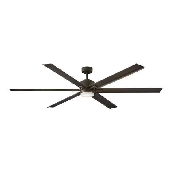
- Página 1 82" INDY MAXX ™ INDOOR / OUTDOOR LED FAN CEILING FAN INSTRUCTION MANUAL...
- Página 2 SO WE’RE HERE IF YOU HAVE A QUESTION, NEED SOME HELP OR WANT TO CHAT ABOUT OUR PRODUCTS. SEND SUGGESTIONS OUR WAY TOO—WE’RE ALWAYS LOOKING TO MAKE YOUR EXPERIENCE WITH HINKLEY A POSITIVE ONE. > SERVICE@HINKLEY.COM > 800.HINKLEY > LET’S SEE THAT HINKLEY STYLE @HINKLEY...
-
Página 3: Tabla De Contenido
INSTALLING THE HANGING BRACKET ENERGY GUIDE HANGING THE FAN SPECIFICATIONS ELECTRICAL CONNECTIONS SMART BY BOND FINISHING THE INSTALLATION INSTALLING THE BLADES WARNING: Read and follow these instructions carefully and be mindful of all warnings shown throughout. ©2020 Hinkley Lighting, Inc. | hinkley.com |... - Página 4 Do not operate the reverse switch while the fan blades are in motion. The fan must be turned off and the blades stopped before reversing the blades direction. | hinkley.com...
-
Página 5: Important Safety Precautions
These factors must be supplied by the person(s) installing, caring for and operating the unit. TOOLS & MATERIALS REQUIRED • PHILLIPS SCREWDRIVER • FLAT SCREWDRIVER • WRENCH OR PLIERS • WIRE CUTTER • STEPLADDER • WIRING SUPPLIES AS REQUIRED BY ELECTRICAL CODE ©2020 Hinkley Lighting, Inc. | hinkley.com |... -
Página 6: Unpacking Your Fan
flat washers, wire nuts), MH90982Fxx Blade to Motor Screws w/Fiber Washers, Balance Kit, Safety cable hardware (wood screw, flat washer) NOTE: Design of parts shown above may look slightly different for XX=FAN FINISH your specific model of fan. | hinkley.com... -
Página 7: Preparation
Loosen screw with key slot and remove canopy. Flat Washer Lock Washer Attach hanging bracket to outlet box using screws provided with the Outlet Box outlet box. Screw Fig. 1 ©2020 Hinkley Lighting, Inc. | hinkley.com |... -
Página 8: Hanging The Fan
Tighten security set screws against downrod using a large flat blade screwdriver to ensure a tight fit against downrod. Downrod Tighten nuts against mounting collar. Security Set Screws Mounting Collar Downrod Pin Cotter Pin Top of Fan Body Fig. 2 | hinkley.com... - Página 9 Safety Cable Loop of the cable into the clamp and pull as much cable through as Wood Screw possible. Firmly tighten screw in the clamp. Cut off excess cable. And Washer Safety Cable Fig. 4 ©2020 Hinkley Lighting, Inc. | hinkley.com |...
-
Página 10: Electrical Connections
RED (to motor) ground wire. Also connect the two GREEN wires (from fan) to building GRAY (to motor) ground wire. YELLOW (to motor) YELLOW (motor) GRAY (motor) Hanger RED (motor) bracket WHITE (motor) BLUE (motor) Receiver Fig. 1 Fig. 2 | hinkley.com... -
Página 11: Finishing The Installation
Make sure the hook on the hanging bracket properly sits in the groove in the hanger ball before attaching the canopy to the bracket by turning the housing until it drops into place. ©2020 Hinkley Lighting, Inc. | hinkley.com |... -
Página 12: Installing The Blades
Secure by tightening the 2 screws previously loosened and the one Mounting Hub previously removed. Light Wires (bottom of motor) Adapter plate Fig. 2 | hinkley.com... -
Página 13: Installing The Led Assembly And Glass Shade
Light Raise the glass shade against the LED assembly and turn clockwise until snug, DO NOT OVERTIGHTEN. assembly Screws Restore power and your LED assembly is ready for operation. Glass Shade Fig. 3 ©2020 Hinkley Lighting, Inc. | hinkley.com |... -
Página 14: Installing The Wall Control
Fig. 1 Install the wall transmitter on the existing wall outlet box using the screws provided. Attached the wall plate with the mounting screws to finish the installation. (Fig. 2) Transmitter Decorative Wall Plate Fig. 2 | hinkley.com... -
Página 15: Operation
Power switch Light button: This button is to control optional light. Switch the "D" and "ON" dip switch on the Fig. 2 front of transmitter to decide the light in "ON/OFF" or "Dimmable" condition. ©2020 Hinkley Lighting, Inc. | hinkley.com |... -
Página 16: Care And Cleaning
WARNING: To reduce the risk of personal injury, do not bend the blade arm while installing, balancing the blades, or cleaning the fan. Do not insert foreign objects between rotating fan blades. 1. Do not connect the fan with a wall mounted variable speed control(s). Remote Control Malfunction. 2. Make sure the dip switches are set correctly. | hinkley.com... -
Página 17: Energy Guide
Airflow Shown Is a Weighted Average of High and Low Cubic Feet per Minute Based on Downrod SMART BY BOND HINKLEY SMART FAN OPTIONS (SOLD SEPARATELY): n addition to the included wall control, you can control your Hinkley fan through the Bond app using the smart technology accessory controls SOLD SEPARATELY. - Página 18 HINKLEY IS PROUD TO PROVIDE YOU WITH CEILING FAN PRODUCTS THAT ENHANCE YOUR SPACE WITH COMFORT, PURPOSE AND STYLE. AS A FAMILY COMPANY, WE ARE COMMITTED TO DESIGN, PERFORMANCE AND QUALITY, AND WHAT’S IMPORTANT TO YOU IS PARAMOUNT TO US.
- Página 19 GLOBAL HEADQUARTERS 33000 Pin Oak Parkway | Avon Lake, Ohio 44012 T (440) 653 5500 | F (440) 653 5555 | hinkley.com...
- Página 20 82" INDY MAXX ™ VENTILADOR LED EXTERIOR / EXTERIOR MANUAL DE INSTRUCCIONES PARA VENTILADORES DE TECHO...
- Página 21 Si no está familiarizado o no se siente cómodo con el cableado, comuníquese con un electricista calificado. Si necesita asistencia adicional o tiene alguna pregunta, comuníquese con nosotros. Para obtener información sobre la garantía, visite hinkley.com.
- Página 22 ESPECIFICACIONES CONEXIONES ELÉCTRICAS INTELIGENTE POR BOND TERMINANDO LA INSTALACIÓN INSTALACIÓN DE LAS CUCHILLAS ADVERTENCIA: Lea y siga estas instrucciones cuidadosamente y tenga en cuenta todas las advertencias que se muestran a lo largo ©2020 Hinkley Lighting, Inc. | hinkley.com |...
-
Página 23: Instrucciones Generales De Instalación
Se puede hacer que el ventilador funcione inmediatamente después de la instalación: los cojinetes están adecuadamente cargados de grasa para que, en condiciones normales, no sea necesaria una mayor lubricación durante la vida útil del ventilador. Para operar la función de retroceso en este ventilador, presione el botón de retroceso mientras el ventilador está funcionando. | hinkley.com... -
Página 24: Precauciones Importantes De Seguridad
HERRAMIENTAS Y MATERIALES REQUERIDOS • DESTORNILLADOR PHILLIPS • DESTORNILLADOR PLANO • LLAVE O ALICATES • CORTADOR DE CABLES • ESCALERA DE TIJERA • SUMINISTROS DE CABLEADO SEGÚN REQUERIDO POR CÓDIGO ELÉCTRICO ©2019 Hinkley Lighting, Inc. | hinkley.com |... -
Página 25: Desembalaje Su Ventilador
Kit de equilibrio, Hardware del cable de seguridad (tornillo para madera, arandela plana) NOTA: El diseño de las piezas que se muestran arriba puede verse XX=ACABADO VENTILADOR ligeramente diferente para su modelo específico de ventilador. | hinkley.com... -
Página 26: Preparación
Tornillo de Fije el soporte para colgar a la caja de salida con los tornillos que se caja de proporcionan con la caja de salida. salida Fig. 1 ©2020 Hinkley Lighting, Inc. | hinkley.com |... -
Página 27: Colgando El Ventilador
Collar de montaje firme contra la varilla. Apriete las tuercas contra el collar de montaje. Pasador de Pasador de chaveta varilla Parte superior del cuerpo del ventilador Fig. 2 | hinkley.com... - Página 28 Introduzca el extremo del cable en la abrazadera y pase la mayor Tornillo y arandela de cantidad de cable posible. Apriete firmemente el tornillo de la abrazadera. madera Corte el cable sobrante. Cable de Fig. 4 seguridad ©2020 Hinkley Lighting, Inc. | hinkley.com |...
-
Página 29: Conexiones Eléctricas
AMARILLO / VERDE. AMARILLO (al motor) • También conecte los dos cables VERDES (del ventilador) al cable de tierra del edificio. AMARILLO (motor) GRIS (motor) ROJO (motor) Soporte de BLANCO (motor) suspensión AZUL (motor) Ventilador Receptor Fig. 2 Fig. 1 | hinkley.com... -
Página 30: Terminando La Instalación
Asegúrese de que el gancho del soporte para colgar se asiente correctamente en la ranura de la bola de suspensión antes de sujetar el dosel al soporte girando la carcasa hasta que encaje en su lugar. ©2020 Hinkley Lighting, Inc. | hinkley.com |... -
Página 31: Instalación De Las Cuchillas
Asegure apretando los 2 tornillos previamente aflojados y el que Mounting Hub previamente quitó. Light Wires (bottom of motor) Adapter plate Fig. 2 | hinkley.com... - Página 32 Empulgueras en el sentido de las agujas del reloj hasta que quede ajustada, NO APRIETE DEMASIADO. Pantalla de Restaure la energía y su conjunto de LED estará listo para funcionar.. vidrio Fig. 3 ©2020 Hinkley Lighting, Inc. | hinkley.com |...
-
Página 33: Instalación Del Control De Pared
Instale el transmisor de pared en la caja de salida de pared existente usando los tornillos provistos. Fije la placa de pared con los tornillos de montaje para finalizar la instalación. (Figura Transmisora Placa de pared decorativa Fig. 2 ©2020 Hinkley Lighting, Inc. | hinkley.com |... -
Página 34: Operación
Botón de luz: Este botón es para controlar la luz Fig. 2 opcional. Cambie el interruptor DIP "D" y "ON" en la parte frontal del transmisor para decidir la luz en la condición "ON / OFF" o "Dimmable". | hinkley.com... -
Página 35: Cuidado Y Limpieza
No inserte objetos extraños entre las aspas giratorias del ventilador. del control remoto 1. No conecte el ventilador con controles de velocidad variable montados en la pared. 2. Asegúrese de que los interruptores DIP estén configurados correctamente. | hinkley.com... -
Página 36: Especificaciones
INTELIGENTE POR BOND OPCIONES DE VENTILADOR INTELIGENTE HINKLEY SE VENDE POR SEPARADO: Además del control de pared incluido, puede controlar su ventilador Hinkley a través de la aplicación Bond. • Para usar la aplicación, descárguela de forma gratuita desde App Store o Google Play. - Página 37 HINKLEY SE ENCUENTRA ORGULLOSO DE PROPORCIONARLE PRODUCTOS PARA VENTILADORES DE TECHO QUE MEJORAN SU ESPACIO CON COMODIDAD, PROPÓSITO Y ESTILO. COMO EMPRESA FAMILIAR, ESTAMOS COMPROMETIDOS CON EL DISEÑO, EL RENDIMIENTO Y LA CALIDAD, Y LO QUE ES IMPORTANTE PARA USTED ES PARAMOUNT PARA NOSOTROS.
- Página 38 GLOBAL HEADQUARTERS 33000 Pin Oak Parkway | Avon Lake, Ohio 44012 T (440) 653 5500 | F (440) 653 5555 | hinkley.com...
- Página 39 82" INDY MAXX ™ VENTILATEUR LED INTÉRIEUR / EXTÉRIEUR MANUEL D'UTILISATION DU VENTILATEUR DE PLAFOND...
- Página 40 NOUS SOMMES ICI SI VOUS AVEZ UNE QUESTION, BESOIN D'UNE AIDE OU VOULEZ CHAT SUR NOS PRODUITS. ENVOYER DES SUGGESTIONS NOTRE FAÇON AUSSI - NOUS CHERCHONS TOUJOURS À FAIRE DE VOTRE EXPÉRIENCE AVEC HINKLEY UNE POSITIVE. > SERVICE@HINKLEY.COM > 800.HINKLEY >...
- Página 41 GUIDE DE L'ÉNERGIE SUSPENDRE LE VENTILATEUR CARACTÉRISTIQUES CONNECTIONS ELECTRIQUES SMART BY BOND FIN DE L'INSTALLATION INSTALLATION DES LAMES AVERTISSEMENT: Lisez et suivez attentivement ces instructions et tenez compte de tous les avertissements indiqués. ©2020 Hinkley Lighting, Inc. | hinkley.com |...
-
Página 42: Instructions Générales D'installation
Le ventilateur peut fonctionner immédiatement après l'installation - les roulements sont correctement chargés de graisse de sorte que, dans des conditions normales, une lubrification supplémentaire ne soit pas nécessaire pendant la durée de vie du ventilateur. Pour activer la fonction d'inversion sur ce ventilateur, appuyez sur le bouton d'inversion pendant que le ventilateur fonctionne. | hinkley.com... -
Página 43: Précautions De Sécurité Importantes
être intégrés à ce produit. Ces facteurs doivent être fournis par la ou les personnes installant, prenant soin et utilisant l'appareil. OUTILS ET MATÉRIAUX REQUIS • TOURNEVIS CRUCIFORME • TOURNEVIS PLAT • CLÉ OU PINCE • COUPE-FIL • ESCABEAU • FOURNITURES DE CÂBLAGE COMME REQUIS PAR LE CODE ÉLECTRIQUE ©2019 Hinkley Lighting, Inc. | hinkley.com |... -
Página 44: Déballage De Votre Fan
Vis de lame à moteur MH90982Fxx avec rondelles en fibre, Kit d'équilibre, Matériel de câble de sécurité (vis à bois, rondelle plate) REMARQUE: La conception des pièces illustrées ci-dessus peut sembler légèrement différente pour votre modèle de ventilateur XX=FINITION DU VENTILATEUR spécifique | hinkley.com... -
Página 45: Préparation
Rondelle à ressort Vis de boîte Fixez le support de suspension à la boîte de sortie à l'aide des vis fournies de sortie avec la boîte de sortie. Fig. 1 ©2020 Hinkley Lighting, Inc. | hinkley.com |... -
Página 46: Suspendre Le Ventilateur
Serrez les vis de sécurité contre la tige de descente à l'aide d'un gros tournevis à lame plate pour assurer un ajustement Goupille de Goupille fendue serré contre la tige de descente. Serrez les écrous contre le tige collier de montage. descendante Haut du corps du ventilateur Fig. 2 | hinkley.com... - Página 47 Faites passer l'extrémité du câble dans la pince et tirez et rondelle autant de câble que possible. Serrez fermement la vis du collier. Couper le câble en excès. Câble de Fig. 4 sécurité ©2020 Hinkley Lighting, Inc. | hinkley.com |...
-
Página 48: Connections Electriques
• Connectez également les deux fils VERT (du ventilateur) au fil de terre du bâtiment. ROUGE (aumoteur) GRIS (au moteur) JAUNE (au moteur) JAUNE (moteur) GRIS (moteur) ROUGE (moteur) Support de suspension BLANC (moteur) BLEU (moteur) Ventilateur Destinataire Fig. 2 Fig. 1 | hinkley.com... -
Página 49: Fin De L'installation
Assurez-vous que le crochet du support de suspension se trouve correctement dans la rainure de la boule de suspension avant de fixer la verrière au support en tournant le boîtier jusqu'à ce qu'il se mette en place. ©2020 Hinkley Lighting, Inc. | hinkley.com |... -
Página 50: Installation De La Plaque De Montage
étroite des trous de clé. Fixez en serrant les 2 vis précédemment Hub de montage desserrées et celle précédemment retirée Fils légers (bas du moteur) Plaque d'adaptation Fig. 2 | hinkley.com... - Página 51 NE PAS TROP SERRER. Abat-jour en Rétablissez l'alimentation et votre assemblage LED est prêt à fonctionner. verre Fig. 3 ©2020 Hinkley Lighting, Inc. | hinkley.com |...
-
Página 52: Installation De La Commande Murale
Fig. 1 Installez l'émetteur mural sur la boîte murale existante à l'aide des vis fournies. Fixez la plaque murale avec les vis de montage pour terminer l'installation. (Fig.2) Plaque murale Émettrice décorative Fig. 2 ©2019 Hinkley Lighting, Inc. | hinkley.com |... -
Página 53: Opération
(vitesse suggérée IV) Interrupteur Bouton d'éclairage: Ce bouton sert à contrôler la lumière en Fig. 2 option. Mettez l'interrupteur DIP "D" et "ON" à l'avant de l'émetteur pour décider de la lumière en "ON / OFF" ou "Dimmable" | hinkley.com... -
Página 54: Dépannage
N'insérez pas d'objets étrangers entre les pales du ventilateur en rotation. Dysfonctionnement de la télécommande 1. Ne connectez pas le ventilateur à une ou plusieurs commandes de vitesse variable fixées au mur. 2. Assurez-vous que les commutateurs DIP sont correctement réglés. | hinkley.com... -
Página 55: Caractéristiques
Le débit d'air affiché est une moyenne pondérée des pieds cubes hauts et bas par minute, basée sur la tige de descente SMART BY BOND OPTIONS DE VENTILATEUR HINKLEY SMART VENDU SÉPARÉMENT: En plus du contrôle mural inclus, vous pouvez contrôler votre ventilateur Hinkley via l'application Bond. • Pour utiliser l'application, téléchargez-la gratuitement depuis l'App Store ou Google Play. - Página 56 HINKLEY EST FIÈRE DE VOUS FOURNIR DES PRODUITS DE VENTILATEUR DE PLAFOND QUI AMÉLIORENT VOTRE ESPACE AVEC CONFORT, OBJECTIF ET STYLE. EN TANT QU'ENTREPRISE FAMILIALE, NOUS NOUS ENGAGEONS À CONCEVOIR, PERFORMANCE ET QUALITÉ, ET CE QUI EST IMPORTANT POUR VOUS EST PARAMOUNT POUR NOUS.
- Página 57 GLOBAL HEADQUARTERS 33000 Pin Oak Parkway | Avon Lake, Ohio 44012 T (440) 653 5500 | F (440) 653 5555 | hinkley.com...