Publicidad
Enlaces rápidos
INSTALLATION AND MAINTENANCE INSTRUCTIONS
IM-10EA
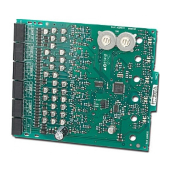
Ten Input Monitor Module
SPECIFICATIONS
Normal Operating Voltage:
Stand-By Current:
Alarm Current:
Temperature Range:
Humidity:
Dimensions:
Accessories:
Wire Gauge:
Maximum SLC Wiring Resistance:
Maximum IDC Wiring Resistance:
Maximum IDC Voltage:
Maximum IDC Current:
BEFORE INSTALLING
This information is included as a quick reference installation guide. Refer to
the appropriate control panel installation manual for detailed system infor-
mation. If the modules will be installed in an existing operational system,
inform the operator and local authority that the system will be temporarily
out of service. Disconnect the power to the control panel before installing the
modules. This system contains static sensitive components. Always ground
yourself with a proper wrist strap before handling any circuits so that static
charges are removed from the body. The housing cabinet should be metallic
and suitably grounded.
NOTICE: This manual should be left with the owner/user of this equipment.
This manual refers only to installations conforming to EN54 requirements.
GENERAL DESCRIPTION
The IM-10EA Ten Input Monitor Module is intended for use in an intelligent
alarm system. Each monitor module is intended to interface between a control
panel and normally open contact devices, such as pull stations. A common
SLC input is used for all modules, and the initiating device loops share a
common supervisory supply and ground. Otherwise, each monitor operates
independently from the others.
Each module also has panel controlled tri-color (green, red and amber)
LED indicators. The panel can cause the LEDs to blink, latch on, or latch off.
The module also provides short circuit isolators to prevent shorts on the fire
detection and alarm system loop from disabling more than one device on the
intelligent loop.
ADDRESSES
In systems using CLIP (Communication Loop Intelligent Protocol) a pair of
rotary code switches is used to set the address of the first module from 01 to
90. The remaining modules are automatically assigned to the next nine higher
addresses. Provisions are included for disabling a maximum of six unused
modules to release the addresses for use elsewhere.
In systems using Advanced Protocol a pair of rotary code switches is used to
set the address of the module from 01 to 159. Only one address is used for the
entire multi-module with sub-addresses completing the remaining addresses.
INCLUDED:
(6) 1 x 4 Terminal Blocks (2) 3.2 cm Stand offs
(4) Screws
15-29 VDC
3.5 mA
60 mA (assumes all ten LEDs solid on)
–10°C to 55°C
10 to 93% Non condensing
17.3cm H x 14.7cm W x 3.2cm D
Suitably grounded metallic cabinet
0.8 mm² - 3.25mm²
40 Ohms
40 Ohms
12 VDC
1 mA
(2) Nuts
(10) 47k Ohm
End of Line Resistors
COMPATIBILITY REQUIREMENTS
To ensure proper operation, this module shall be connected to a listed compat-
ible system control panel.
In order to comply with EN54-17 and EN54-18 requirements the modules
must be installed within a grounded, metal enclosure that is suitable for the
application. The CE marking label confirms compliance with CPD, and must
be applied to the module enclosure only once installation of the module in
the enclosure is completed. The label shall be mounted in a position that is
visible during installation and accessible during maintenance. The label shall
not be placed on screws or other easily removable parts.
WIRING
NOTE: All wiring must conform to applicable local codes, ordinances, and
regulations.
1.
Install module wiring in accordance with the job drawings and appropri-
ate wiring diagrams.
2.
All wiring to the IM-10EA is done via terminal blocks. In order to properly
make electrical connections strip approximately .6 cm of insulation from the
end of wire, sliding the bare end of the wire under the clamping plate screw.
3.
Set the address on the modules per the job drawing. Use the rotary code
switches to set the address of the module. (refer to Addresses section)
NOTE: In CLIP the remaining modules are automatically assigned to the next
nine higher addresses. For example, if the base address switch is set to 28, the
next nine modules will be addressed to 29, 30, 31, 32, 33, 34, 35, 36, and 37.
DO NOT set the lowest address above 90, as the other modules will be as-
signed to nonexistent addresses.
4.
A dip switch is provided to disable a maximum of six unused modules
in CLIP. Modules are disabled from the highest address and work down-
ward. If two modules are disabled, the lowest eight addresses will be
functional, while the highest two will be disabled. For example, if the
dip switch is set to disable two addresses and the base code wheel is set
to 28, the modules will be assigned to 28, 29, 30, 31, 32, 33, 34 and 35
while disabling the highest two positions.
1
Honeywell Products and Solutions Sàrl
Zone d'Activités La Pièce 16
CH-1180 ROLLE, Switzerland
I56-3918-004
2/28/2020
Publicidad

Manuales relacionados para Honeywell System Sensor IM-10EA


Resumen de contenidos para Honeywell System Sensor IM-10EA
- Página 1 INSTALLATION AND MAINTENANCE INSTRUCTIONS IM-10EA Honeywell Products and Solutions Sàrl Ten Input Monitor Module Zone d’Activités La Pièce 16 CH-1180 ROLLE, Switzerland SPECIFICATIONS Normal Operating Voltage: 15-29 VDC Stand-By Current: 3.5 mA Alarm Current: 60 mA (assumes all ten LEDs solid on) Temperature Range: –10°C to 55°C...
- Página 2 NOTE: DO NOT mix fire alarm initiating and supervisory devices on the same initiating device circuit. Install contact closure devices per manufacturer’s installation instructions. 0905 Honeywell Products and Solutions Sàrl Zone d’ A ctivités La Pièce 16 CH-1180 ROLLE, Switzerland...
- Página 3 ISTRUZIONI DI INSTALLAZIONE E MANUTENZIONE IM-10EA Honeywell Products and Solutions Sàrl Modulo di controllo a dieci ingressi Zone d’Activités La Pièce 16 CH-1180 ROLLE, Switzerland SPECIFICHE Tensione normale di esercizio: 15-29 VDC Corrente di riserva: 3,5 mA Corrente di allarme:...
- Página 4 NOTA: NON mescolare dispositivi di sorveglianza e di attivazione antincendio nello stesso circuito del dispositivo di attivazione. Installare dispositivi di chiusura di contatto in base alle istruzioni di instal- lazione del produttore. 0905 Honeywell Products and Solutions Sàrl Zone d’ A ctivités La Pièce 16 CH-1180 ROLLE, Switzerland 0905-CPR-191779...
-
Página 5: Módulo De Supervisión De Diez Entradas
INSTRUCCIONES DE INSTALACIÓN Y MANTENIMIENTO IM-10EA Honeywell Products and Solutions Sàrl Módulo de supervisión de diez entradas Zone d’Activités La Pièce 16 CH-1180 ROLLE, Switzerland ESPECIFICACIONES Tensión operativa normal: de 15 a 29 VCC Corriente en espera: 3,5 mA Corriente de alarma:... - Página 6 Instale dispositivos de cierre de contactos según las instrucciones de insta- lación del fabricante. 0905 Honeywell Products and Solutions Sàrl Zone d’ A ctivités La Pièce 16 CH-1180 ROLLE, Switzerland 0905-CPR-191779...
- Página 7 INSTALLATIONS- UND WARTUNGSANLEITUNG IM-10EA Honeywell Products and Solutions Sàrl Überwachungsmodul mit zehn Eingängen Zone d’Activités La Pièce 16 CH-1180 ROLLE, Switzerland SPEZIFIKATION Betriebsspannungsbereich: 15 – 29 V DC Ruhestrom: 3,5 mA Alarmstrom: 60 mA (bei zehn dauerleuchtenden LEDs) Temperaturbereich: -10 °C bis 55 °C...
- Página 8 HINWEIS: Brandmelde- und Überwachungsmodule dürfen NICHT in derselben IDC-Schleife gemischt verwendet werden. Installieren Sie Kontaktschließvorrichtungen entsprechend der Installationsanleitung des Herstellers. 0905 Honeywell Products and Solutions Sàrl Zone d’ A ctivités La Pièce 16 CH-1180 ROLLE, Switzerland 0905-CPR-191779 EN 54-18: 2005 + AC: 2007...