Tabla de contenido
Publicidad
Idiomas disponibles
Idiomas disponibles
Enlaces rápidos
π
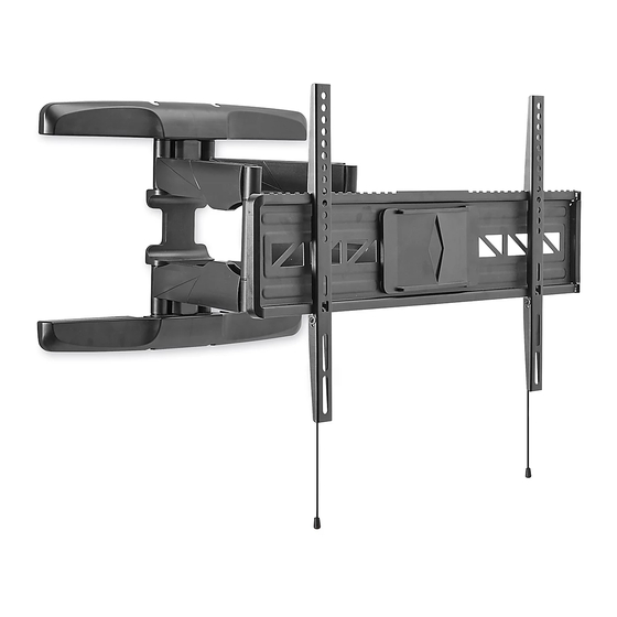
H-10162
WALL MONITOR MOUNT –
32-80" FULL MOTION
TOOLS NEEDED
Electric
Phillips Head
Drill
Drill Bit
Phillips
Tape Measure
Screwdriver
Plastic Cover x 2
Wall Plate x 1
Plastic
Cap x 2
Cable Management
CAUTION! This product is designed to be
installed on solid concrete walls or drywall with
wood studs. Before installing, ensure wall will
support the combined load of the equipment.
CAUTION! Be careful not to scratch the monitor
screen during assembly.
ATTACHING TO WALL
CONCRETE WALL
1. Align wall plate in desired location. Place level on
top of the wall plate to ensure it is leveled correctly.
Mark where holes for screws are to be located.
(See Figure 1)
NOTE: Mark four hole locations on the top
section of wall plate, and two hole locations
on the bottom section.
PAGE 1 OF 14
1-800-295-5510
3/16" Drill Bit
3/8" Drill Bit
Magnetic Level
(included)
B1
Bracket x 2
Screw x 6
Monitor
A6
Plate x 1
Bracket
Square
String x 2
Washer x 4
Cable Management
Clip A x 4
Clip B x 2
INSTALLATION
uline.com
6 x 6 mm Allen Wrench
(included)
Box Wrench
(included)
Stud Finder
PARTS
B2
Plastic
Lag
Anchor x 6
A5
Spacer x 4
B3
Washer x 6
Figure 1
Para Español, vea páginas 5-9
Pour le français, consulter les pages 10-14
Two-Person Assembly
Recommended
A1
M4 x 12 mm Bolt x 4
M4 x 25 mm Bolt x 4
A2
M5 x 12 mm Bolt x 4
M5 x 25 mm Bolt x 4
A3
M6 x 12 mm Bolt x 4
M6 x 25 mm Bolt x 4
A4
M8 x 16 mm Bolt x 4
M8 x 25 mm Bolt x 4
Level
Concrete
Wall
Plate
Wall
1122 IH-10162
Publicidad
Tabla de contenido

Manuales relacionados para Uline H-10162


Resumen de contenidos para Uline H-10162
- Página 1 Para Español, vea páginas 5-9 Pour le français, consulter les pages 10-14 π H-10162 1-800-295-5510 uline.com WALL MONITOR MOUNT – 32-80" FULL MOTION TOOLS NEEDED Electric Phillips Head 3/16" Drill Bit 6 x 6 mm Allen Wrench Drill Drill Bit 3/8"...
- Página 2 INSTALLATION CONTINUED DRYWALL 2. Drill six 2⁄" deep holes using 3/8" drill bit. Insert plastic anchors (B2) into pre-drilled holes. WARNING! If mounting to drywall, wall plate (See Figure 2) must be properly attached to wood studs NOTE: It is recommended to use a masonry drill behind the wall in order to hold the listed bit for concrete walls.
- Página 3 INSTALLATION CONTINUED ATTACHING BRACKETS TO MONITOR CONNECTING BRACKETS TO MONITOR PLATE Determine bolt size that is compatible with the monitor. Using the square washers and spacers, install each Place plastic caps over the ends of the monitor bracket to the monitor. plate.
-
Página 4: Removing The Monitor
With second person, pull down on the strings attached to the brackets. This will unlock the brackets from the wall plate, and the monitor can be removed. (See Figure 11) Figure 11 Figure 11 1-800-295-5510 uline.com PAGE 4 OF 14 1122 IH-10162... -
Página 5: Herramientas Necesarias
π H-10162 800-295-5510 uline.mx SOPORTE DE PARED PARA PANTALLA – MOVIMIENTO TOTAL DE 32-80" HERRAMIENTAS NECESARIAS Taladro Broca Broca de 3/16" Llave Allen 6 x 6 mm Eléctrico de Cruz Broca de 3/8" (Incluida) Desarmador Nivel Magnético Llave de Estrías... -
Página 6: Continuación De Instalación
CONTINUACIÓN DE INSTALACIÓN PANEL DE YESO 2. Perfore seis orificios de 2⁄" de profundidad utilizando la broca de 3/8". Inserte los taquetes de ¡ADVERTENCIA! Si se instala en un panel plástico (B2) en los orificios preperforados. de yeso, la placa para pared se debe fijar (Vea Diagrama 2) adecuadamente a las vigas de madera detrás NOTA: Se recomienda usar una broca para... -
Página 7: Conectar Soportes A La Placa Para Monitor
CONTINUACIÓN DE INSTALACIÓN 4. Con el nivel magnético fijado, instale la placa para NOTA: Para monitores con respaldo curvo u pared utilizando cuatro tornillos tirafondo (B1) y obstrucciones, coloque los separadores (A5) rondanas (B3). (Vea Diagrama 5) en el lado más cercano al monitor. (Vea Diagrama 7) Diagrama 5 Diagrama 7... -
Página 8: Ajustar El Monitor Y Organizar El Cableado
CONTINUACIÓN DE INSTALACIÓN 2. Con la ayuda de otra persona, levante y alinee con cuidado los soportes en el respaldo del monitor con la placa para monitor. Incline la parte superior del monitor hacia la pared y coloque la parte superior de los soportes sobre la placa para monitor. -
Página 9: Retirar El Monitor
Con la ayuda de una segunda persona, jale hacia abajo de las cuerdas fijadas a los soportes. Esto desbloqueará los soportes de la placa para pared y el monitor se podrá retirar. (Vea Diagrama 11) Diagrama 11 Diagrama 800-295-5510 uline.mx PAGE 9 OF 14 1122 IH-10162... -
Página 10: Outils Requis
π H-10162 1-800-295-5510 uline.ca SUPPORT MURAL À PLEIN MOUVEMENT POUR MONITEUR – 32 À 80 PO OUTILS REQUIS Perceuse Mèche de Mèche de perceuse de 3/16 po Clé Allen de 6 x 6 mm électrique perceuse Mèche de perceuse de 3/8 po... - Página 11 INSTALLATION SUITE CLOISON SÈCHE 2. Percez six trous de 2 ⁄ po de profondeur en utilisant une mèche de perceuse de 3/8 po. Insérez les AVERTISSEMENT! Si le montage est effectué sur ancrages en plastique (B2) dans les trous prépercés. ARRÊT une cloison sèche, la plaque murale doit être (Voir Figure 2)
- Página 12 INSTALLATION SUITE 4. Avec le niveau à bulle magnétique toujours attaché, REMARQUE : Pour les moniteurs à dos incurvé fixez la plaque murale avec quatre tirefonds (B1) et ou avec des obstructions, placez les espaceurs rondelles (B3). (Voir Figure 5) (A5) du côté le plus proche du moniteur. (Voir Figure 7) Figure 5 Niveau...
- Página 13 INSTALLATION SUITE 2. À deux, soulevez le moniteur avec précaution et alignez les supports à l'arrière du moniteur sur la plaque murale. Inclinez le haut du moniteur vers le mur et placez la partie supérieure des supports sur la plaque de moniteur. Tournez lentement le bas du moniteur vers le mur et enclenchez la partie inférieure des supports sur la plaque de moniteur.
-
Página 14: Retrait Du Moniteur
À deux, tirez vers le bas sur les ficelles attachées aux supports. Cela déverrouille les supports de la plaque murale et le moniteur peut être retiré. (Voir Figure 11) Figure 11 Figure 11 1-800-295-5510 uline.ca PAGE 14 OF 14 1122 IH-10162...