Tabla de contenido
Publicidad
Idiomas disponibles
Idiomas disponibles
Enlaces rápidos
52 IN. CEILING FAN
INSTRUCTION MANUAL
CATALOG NUMBER
BCF5262R
Thank you for choosing BLACK+DECKER!
PLEASE READ BEFORE RETURNING THIS PRODUCT FOR
ANY REASON.
If you have a question or experience a problem with your BLACK+DECKER
purchase, go to www.blackanddecker.com/instantanswers
If you can't find the answer or do not have access to the Internet, call
844-299-0879 from 10:30 a.m. to 6:30 p.m. EST Mon. - Fri. to speak with an
agent. Please have the catalog number available when you call.
SAVE THIS MANUAL FOR FUTURE REFERENCE.
Publicidad
Capítulos
Tabla de contenido
Solución de problemas

Manuales relacionados para Black and Decker BCF5262R


Resumen de contenidos para Black and Decker BCF5262R
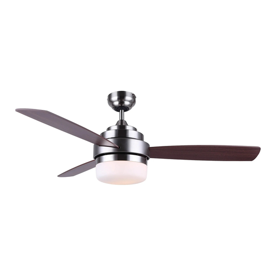
- Página 1 52 IN. CEILING FAN INSTRUCTION MANUAL CATALOG NUMBER BCF5262R Thank you for choosing BLACK+DECKER! PLEASE READ BEFORE RETURNING THIS PRODUCT FOR ANY REASON. If you have a question or experience a problem with your BLACK+DECKER purchase, go to www.blackanddecker.com/instantanswers If you can’t find the answer or do not have access to the Internet, call 844-299-0879 from 10:30 a.m.
-
Página 2: Tabla De Contenido
CONTENTS SAFETY INFORMATION Important Safety Instructions ............................3-4 Handling Alkaline Batteries ..............................5 SET UP & USE Parts ......................................6-7 Features ......................................8 Preparing for Installation ............................9 Mounting Bracket Installation .........................10-11 Mounting Fan to Ceiling ........................... 12-14 Wiring Options ..............................15-16 Securing Fan to Ceiling ............................17 Blade Installation ..............................18 Light Fixture Installation ............................19... -
Página 3: Safety Information
SAFETY INFORMATION DANGER WARNING CAUTION DANGER - Immediate hazards WARNING - Hazards or unsafe CAUTION - Hazards or unsafe which WILL result in severe practices which COULD result in practices which COULD result in personal injury or death severe personal injury or death minor personal injury IMPORTANT SAFETY INSTRUCTIONS WARNING... - Página 4 SAFETY INFORMATION 9. To reduce the risk of fire, electric shock, or personal injury, this fan must be mounted to an outlet box marked suitable for fan support. And use mounting screws provided with the outlet box. (Mounting must support at least 35 lbs. (15.9 kg) 10.
-
Página 5: Handling Alkaline Batteries
SAFETY INFORMATION HANDLING ALKALINE BATTERIES WARNING When handling alkaline batteries, basic safety precautions should be followed, including the following 1. Should fluid from the battery accidentally get into your eyes, there is a threat of loss of eyesight, do not rub them. Immediately rinse your eyes with clean tap water and then consult a physician immediately. -
Página 6: Set Up & Use
SET UP & USE PARTS Mounting Bracket 6” Downrod Canopy Slide Switch Motor Housing Blade (3) *Light Fixture Hardware Pack Screws Screws for fan blade *Remote Control and holder Wire Connectors Washers for fan blade *Remote Receiver * Batteries not included with remote. Use (2) size “AA” alkaline batteries. * Bulbs not included with light fixture (2) type A-19, 60W bulbs required. -
Página 7: Parts Included
E. Fan Motor Assembly B. Canopy F. Motor Cover C. 6” Downrod assembly G. Glass Cover (Light Fixture) D. Yoke Cover H. Fan Blades (3) BCF5262R Remote Control Remote Receiver Remote Control Holder 2 Screws for Remote Control Holder RECOMMENDED TOOLS Ladder... -
Página 8: Features
SET UP & USE FEATURES Flush Downrod Vaulted Ceiling Installation Installation Installation For normal ceilings For normal ceilings May require a longer downrod (sold separately) CAUTION To reduce the risk of injury to persons, the fan must be installed so that the blades are at a height greater than 7 feet (2.1 meters) above the floor. -
Página 9: Preparing For Installation
SET UP & USE PREPARING FOR INSTALLATION 1. Unpack and inspect fan carefully to be certain all contents are included. WARNING: Turn off power at the breaker box or fuse panel to avoid possible electrical shock. 2. Use a listed metal outlet box suitable for fan support (rated for 35 lbs (15.9 kg)). Before attaching fan to outlet box, ensure the outlet box is securely fastened by at least two points to a structural ceiling member (a loose box will cause the fan to wobble). -
Página 10: Mounting Bracket Installation
SET UP & USE MOUNTING BRACKET INSTALLATION 3. Remove the screws from the two mating holes (2) on the canopy. Loosen (do not remove) the screws in the mating slots (1) on the canopy. Rotate the mounting bracket and remove from the canopy. Page 10... - Página 11 SET UP & USE 4. Install mounting bracket to outlet box in ceiling using the screws and washers provided with the outlet box. Page 11...
-
Página 12: Mounting Fan To Ceiling
SET UP & USE 5. Choose a MOUNTING OPTION (Shown on page 8): FLUSH INSTALLATION OPTION If installing flush, remove the screws from the canopy and reinstall 3 screws to attach the canopy to the motor housing as shown. Screws Canopy Motor Housing... - Página 13 SET UP & USE DOWNROD INSTALLATION 7. Insert motor wires through the selected downrod and insert the downrod into the downrod coupling. Make sure to align the hole in the downrod with the hole in the downrod coupling. Install cross pin (1) removed in step 6 through coupling and downrod.
- Página 14 SET UP & USE MOUNTING 8. Carefully lift fan assembly onto mounting bracket. Rotate fan until notch on downrod ball (1) engages the ridge on the mounting bracket (2). This will allow for hands free wiring for downrod fan installation. NOTE: If you are installing the fan flush, you will need assistance holding the fan while doing the wiring.
-
Página 15: Wiring Options
SET UP & USE WIRING OPTIONS FOR BCF5262R WITH REMOTE 9. The frequency switches on your receiver and transmitter have been preset at the factory. Please recheck to make sure the switches on transmitter and receiver are set to the same position, any combination of settings will operate the fan as long as the transmitter and receiver are set to the same position. - Página 16 SET UP & USE 10. Make wiring connections from the ceiling and the fan motor to the remote receiver as shown above. Connect using wire connectors (provided). Ceiling 11. Once wiring has been completed insert the remote receiver at the top of the mounting bracket as shown.
-
Página 17: Securing Fan To Ceiling
SET UP & USE SECURE TO CEILING 12. The canopy has two mating slots (1) and two mating holes (2). Position both slots on canopy directly under and in line with two screws in the mounting bracket (3). Lift the canopy, allowing the two screws to slide into the mating slots. Rotate the canopy until both screws from the mounting bracket drop into the slot recesses. -
Página 18: Blade Installation
SET UP & USE BLADE INSTALLATION 13. Attach the blades to the blade brackets in the fan motor assembly using 3 screws and 3 washers for each blade. Blade Bracket Screw Washers Blade Blade Bracket Remove 3 light kit screws and 3 washers from the fan motor housing. Insert the 2 appropriate sized light kit connections from the fan motor assembly to the motor cover. -
Página 19: Light Fixture Installation
SET UP & USE LIGHT FIXTURE INSTALLATION 14. Install 2 light bulbs Type A-19, 60W max (not included). 15. Locate the indentations on the neck of the glass (2) and align with the protrusions from the light kit (1). Lift the glass up allowing the protrusions to engage the indentations on the glass, and twist the glass clockwise to lock into place. - Página 20 SET UP & USE 16. Mount the remote control holder onto the wall using the screws provided. If you do not wish to screw the remote holder into the wall, you may purchase some adhesive at your local hardware store. Page 20...
-
Página 21: Remote Control Operation
SET UP & USE REMOTE CONTROL OPERATION Operation button on the remote: Fan high speed Fan medium speed Fan low speed Fan off Light on/off Light dimmer NOTE: Hold down to increase or decrease the light. The light has a memory function so the light will stay at the same brightness as the last time it was turned off. -
Página 22: Operation
SET UP & USE OPERATION The slide switch controls direction, forward or reverse. Warm weather - switch on left position. Fan turns counterclockwise direction. A downward air flow creates a cooling effect as shown in illustration A. Cool weather - switch on right position (see image). Fan turns clockwise direction. -
Página 23: Cleaning + Maintenance
CLEANING + MAINTENANCE CLEANING + MAINTENANCE 1. Because of the fan’s natural movement, some connections may become loose. Check the support connections, brackets, and blade attachments twice a year. Make sure they are secure. 2. Clean your fan periodically to help maintain its new appearance over the years. Do not use water when cleaning. -
Página 24: Before You Call For Service
SET UP & USE BEFORE YOU CALL FOR SERVICE IF THE APPLIANCE FAILS TO OPERATE: Check for a blown circuit fuse or a tripped main circuit breaker. If these seem to be operating properly, test the outlet with another appliance. IF NONE OF THE ABOVE SOLVES THE PROBLEM, CONTACT A QUALIFIED TECHNICIAN. -
Página 25: Troubleshooting
TROUBLESHOOTING & WARRANTY Troubleshoot your problem by using the chart below. If the appliance still does not work properly, contact W Appliance Co. customer service center. Customers must never troubleshoot internal components. TROUBLE POSSIBLE REMEDY 1. Check main and branch circuit fuses or circuit breakers. 2. -
Página 26: Limited Warranty
TROUBLESHOOTING & WARRANTY LIMITED WARRANTY Any repair, replacement, or warranty service, REPAIR OR REPLACEMENT AS PROVIDED UNDER THIS WARRANTY IS THE EXCLUSIVE REMEDY OF and all questions about this product should be THE CUSTOMER; W Appliance Co. SHALL NOT BE directed to W Appliance Co. - Página 27 This device complies with part 15 of the FCC rules. Operation is subject to the following two conditions: 1) This device may not cause harmful interference, and 2) This device must accept any interference received, including interference that may cause undesired operation. This equipment has been tested and found to comply with the limits for a Class B digital device, pursuant to Part 15 of the FCC rules.
- Página 28 Page 28...
- Página 29 VENTILADOR DE TECHO DE 52” MANUEL D’UTILISATION NUMÉRO DE CATALOGUE BCF5262R Merci d’avoir choisi BLACK+DECKER! VEUILLEZ LIRE AVANT DE RETOURNER CE PRODUIT POUR QUELQUE RAISON. Si vous avez une question ou rencontrez un problème avec votre achat BLACK+DECKER, allez à www.blackanddecker.com/instantanswers Si vous ne trouvez pas la réponse ou n’avez pas accès à...
-
Página 30: Enregistrement Du Produit
TABLE DES MATIÈRES INFORMATIONS DE SÉCURITÉ Information sur la sécurité .............................31-32 Manipulation des Piles Alcalines .............................33 CONFIGURATION ET UTILISATION Pièces ..................................... 34-35 Caractéristiques ..................................36 Préparation à l’Installation ............................37 Installation du Support de Montage ......................38-39 Montage du Ventilateur au Plafond ......................40-42 Options de Câblage ............................ -
Página 31: Informations De Sécurité
INFORMATIONS DE SÉCURITÉ DANGER ATTENTION MISE EN GARDE ATTENTION - Dangers ou pratiques MISE EN GARDE - Dangers ou DANGER - Dangers immédiats qui dangereuses qui POURRAIENT pratiques dangereuses pouvant entraîneront des blessures graves entraîner des blessures graves ou entraîner des blessures corporelles ou la mort la mort mineures... - Página 32 INFORMATIONS DE SÉCURITÉ 7. Lors de la coupe ou du perçage dans le mur ou le plafond, ne pas endommager le câblage électrique et les autres accessoires cachés. 8. Assurez-vous que le site d’installation choisi permet aux pales du ventilateur de tourner sans aucune obstruction. Laissez un espace minimum de 7 pieds (2.1 mètres) du sol jusqu’au bord traînant de la pale.
-
Página 33: Manipulation Des Piles Alcalines
INFORMATIONS DE SÉCURITÉ MANIPULATION DES PILES ALCALINES ATTENTION Lors de la manipulation des piles alcalines, des précautions de sécurité de base doivent être suivies, y compris les suivantes 1. Si le liquide de la pile entre accidentellement dans vos yeux, il y a une menace de perte de la vue, ne pas les frotter. -
Página 34: Configuration Et Utilisation
CONFIGURATION ET UTILISATION PIÈCES Support de Montage Tige de 6” Canopée Interrupteur à Glissière Boîtier du Moteur Pale (3) *Luminaire Paquet Quincaillerie Vis pour pale de ventilateur *Télécommande et support Serre-fils Rondelles pour pale de ventilateur *Récepteur à Distance * Piles non fournies avec la télécommande. Utilisez (2) piles alcalines “AA”. * Ampoules non incluses avec le luminaire (2) ampoules type A-19, de 60W requises. -
Página 35: Pièces Incluses
CONFIGURATION ET UTILISATION PIÈCES INCLUSES A. Support de Montage E. Assemblée du Moteur du Ventilateur B. Canopée F. Couvercle de Moteur C. Ensemble de tige de 6po G. Couvercle de Verre (Luminaire) D. Couvercle de Culasse H. Pales de Ventilateur (3) BCF5252R Télécommande Récepteur à... -
Página 36: Caractéristiques
CONFIGURATION ET UTILISATION CARACTÉRISTIQUES Installation Installation Installation au Encastrée sur Tige Plafond Voûté Pour les plafonds Pour les plafonds Peut nécessiter une normaux normaux tige de suspension plus longue (vendue séparément) ATTENTION Pour réduire le risque de blessure aux personnes, le ventilateur doit être installé de sorte que les pales soient à... -
Página 37: Préparation À L'installation
CONFIGURATION ET UTILISATION PRÉPARER POUR L’INSTALLATION 1. Déballez et inspectez soigneusement le ventilateur pour vous assurer que tout le contenu est inclus. Coupez l’alimentation à la boîte à fusibles pour éviter tout risque d’électrocution. 2. Utilisez une boîte de sortie en métal homologuée convenant au support du ventilateur (capacité... -
Página 38: Installation Du Support De Montage
CONFIGURATION ET UTILISATION INSTALLATION DU SUPPORT DE MONTAGE 3. Retirez les vis des deux trous correspondants (2) sur la canopée. Desserrez (ne retirez pas) les vis dans les fentes d’accouplement (1) sur la canopée. Tournez le support de montage et retirez-le de la canopée. Page 38... - Página 39 CONFIGURATION ET UTILISATION 4. Installez le support de montage sur la boîte de sortie du plafond à l’aide des vis et des rondelles fournies avec la boîte de sortie. Page 39...
-
Página 40: Montage Du Ventilateur Au Plafond
CONFIGURATION ET UTILISATION 5. Choisissez une OPTION DE MONTAGE (illustrée à la page 8): OPTION D’INSTALLATION ENCASTRÉE Si vous l’installez encastré, retirez les vis de la canopée et réinstallez 3 vis pour fixer la canopée au boîtier du moteur comme indiqué. Des vis Logement Canopée... -
Página 41: Installation De La Tige De Suspension
CONFIGURATION ET UTILISATION INSTALLATION DE LA TIGE DE SUSPENSION 7. Insérez les fils du moteur dans la tige de suspension sélectionnée et insérez la tige dans le couplage de la tige. Assurez-vous d’aligner le trou de la tige avec le trou dans le couplage de la tige. - Página 42 CONFIGURATION ET UTILISATION MONTAGE 8. Soulevez soigneusement l’assemblage du ventilateur sur le support de montage. Tournez le ventilateur jusqu’à ce que l’encoche de la bille de guidage (1) s’engage dans l’arête du support de montage (2). Cela permettra un câblage à mains libres pour l’installation à...
-
Página 43: Options De Câblage
CONFIGURATION ET UTILISATION OPTIONS DE CÂBLAGE POUR BCF5262R AVEC TÉLÉCOMMANDE 9. Les commutateurs de fréquence de votre récepteur et émetteur ont été préréglés en usine. Veuillez revérifier que les commutateurs de l’émetteur et du récepteur sont réglés sur la même position, toute combinaison de réglages fera fonctionner le ventilateur tant que l’émetteur et le récepteur sont réglés sur la même position. - Página 44 CONFIGURATION ET UTILISATION 10. Effectuez les connexions de câblage du plafond et du moteur du ventilateur au récepteur à distance comme indiqué ci-dessus. Connectez en utilisant des connecteurs de fils (fournis). Ceiling 11. Une fois le câblage terminé, insérez le récepteur à distance en haut du support de montage comme indiqué.
-
Página 45: Fixation Du Ventilateur Au Plafond
CONFIGURATION ET UTILISATION SÉCURISER AU PLAFOND 12. La canopée comporte deux fentes de couplage (1) et deux trous de couplage (2). Positionnez les deux fentes de la canopée directement sous et alignées avec les deux vis du support de montage (3). Soulevez la canopée en laissant les deux vis glisser dans les fentes de couplage. -
Página 46: Installation De Pale
CONFIGURATION ET UTILISATION INSTALLATION DE LA PALE 13. Fixez les lames aux supports de lame dans le moteur du ventilateur en utilisant 3 vis et 3 rondelles pour chaque lame. Montez le couvercle du moteur sur l’ensemble du moteur du ventilateur, en alignant les vis dans l’ensemble du ventilateur du moteur avec les fentes de la clé... -
Página 47: Installation Du Luminaire
CONFIGURATION ET UTILISATION INSTALLATION DE LUMINAIRE 14. Installez 2 ampoules de type A-19, 60W max (non incluses). 15. Localisez les indentations sur le col du verre (2) et alignez-les avec les saillies du kit d’éclairage (1). Soulevez le verre en laissant les saillies s’engager dans les indentations sur le verre et tournez le verre dans le sens horaire pour le verrouiller en place. - Página 48 CONFIGURATION ET UTILISATION 16. Montez le support de télécommande sur le mur à l’aide des vis fournies. Si vous ne souhaitez pas visser le support de télécommande dans le mur, vous pouvez acheter de l’adhésif dans votre quincaillerie locale. Page 48...
-
Página 49: Fonctionnement De La Télécommande
CONFIGURATION ET UTILISATION FONCTIONNEMENT DE LA TÉLÉCOMMANDE Bouton d’opération sur la télécommande: Ventilateur haute vitesse Ventilateur moyenne vitesse Ventilateur basse vitesse Ventilateur arrêt Lumière marche/arrêt Gradateur REMARQUE: Maintenez enfoncé pour augmenter ou diminuer la lumière. La lumière a une fonction de mémoire afin que la lumière reste à... -
Página 50: Opération
CONFIGURATION ET UTILISATION OPÉRATION Le commutateur à glissière commande la direction, vers l’avant ou vers l’arrière. Temps chaud - l’interrupteur est en position de gauche. Le ventilateur tourne dans le sens antihoraire. Un flux d’air vers le bas crée un effet de refroidissement comme indiqué... -
Página 51: Nettoyage + Entretien
NETTOYAGE + ENTRETIEN NETTOYAGE + ENTRETIEN 1. À cause du mouvement naturel du ventilateur, certaines connexions peuvent se desserrer. Vérifiez les connexions de support, les supports et les attaches de pale deux fois par an. Assurez-vous qu’ils sont sécurisés. 2. Nettoyez votre ventilateur périodiquement pour aider à conserver son aspect neuf au fil des ans. -
Página 52: Dépannage Et Garantie
DÉPANNAGE ET GARANTIE AVANT D’APPELER POUR LE SERVICE SI L’APPAREIL NE FONCTIONNE PAS: Assurez-vous que l’appareil est branché solidement. Si ce n’est pas le cas, retirez la fiche de la prise, attendez 10 secondes et branchez-le à nouveau sécuritairement. SI AUCUNE DE CES RÉPONSES RÉSOUT LE PROBLÈME, CONTACTEZ UN TECHNICIEN QUALIFIÉ. -
Página 53: Dépannage
DÉPANNAGE ET GARANTIE Localisez votre problème en utilisant le tableau ci-dessous. Si le climatiseur ne fonctionne toujours pas correctement, contactez le service clientèle de W Appliance Co. ou le centre de service agréé le plus proche. Les clients ne doivent jamais dépanner les composants internes. -
Página 54: Garantie Limitée
DÉPANNAGE ET GARANTIE GARANTIE LIMITÉE Toute réparation, remplacement ou réparation de remplacement. 14. Appels de service pour vous apprendre sous garantie, et toutes les questions sur ce á utiliser votre produit. produit doivent être adressées à W Appliance 15. Les appels de service pour réparer Co. - Página 55 Cet appareil respecte la section 15 des directives FCC. Son utilisation est soumise aux deux conditions suivantes: 1) cet appareil ne doit pas causer aucune interférence nuisible; et 2) cet appareil doit accepter toute interférence reçue, y compris les interférences susceptibles de provoquer un fonctionnement indésirable. Ce matériel a été...
- Página 56 Page 56...
-
Página 57: Ventilador De Techo De 52 Pulgadas
VENTILADOR DE TECHO DE 52 PULGADAS (132 CM) MANUAL DE INSTRUCCIONES NÚMERO DE CATÁLOGO BCF5262R ¡Gracias por elegir Black+Decker! POR FAVOR, LEER ANTES DE DEVOLVER ESTE PRODUCTO POR CUALQUIER MOTIVO. Si tiene alguna pregunta o experimenta un problema con su compra de Black+Decker, vaya a www.blackanddecker.com/instantanswers... -
Página 58: Registro De Producto
CONTENIDO INFORMACIÓN DE SEGURIDAD Instrucciones de Seguridad Importantes ......................59-60 Manipulación de baterías alcalinas ...........................61 CONFIGURACIÓN Y USO Partes ..................................... 62-63 Características ..................................64 Preparación para la instalación ...........................65 Instalación del soporte de montaje ......................66-67 Montaje del ventilador al techo ........................68-70 Opciones de cableado ............................ 71-72 Asegurar el ventilador al techo ...........................73 Instalación de las aspas............................74 Instalación de luminarias ............................75... -
Página 59: Información De Seguridad
INFORMACIÓN DE SEGURIDAD PELIGRO PRECAUCIÓN ADVERTENCIA Peligros inmediatos que resultarán Peligros o prácticas inseguras Peligros o prácticas inseguras en lesiones personales graves o la que pueden resultar en lesiones que pueden resultar en lesiones muerte personales graves o la muerte personales menores IMPORTANTES INSTRUCCIONES DE SEGURIDAD... -
Página 60: Safety Information
SAFETY INFORMATION 7. Al cortar o taladrar en la pared o el techo, no dañe el cableado eléctrico u otros servicios ocultos. 8. Asegúrese de que el sitio de instalación que elija permita que las aspas del ventilador giren sin obstrucciones. Deje un espacio libre mínimo de 7 pies (2,1 metros) desde el piso hasta el borde posterior de las aspas. -
Página 61: Manejo De Baterías Alcalinas
SAFETY INFORMATION MANEJO DE BATERÍAS ALCALINAS ADVERTENCIA Al manejar baterías alcalinas, deben seguirse las medidas básicas de precaución, detalladas a continuación. 1. Si el líquido de la batería entra accidentalmente en contacto con sus ojos, existe el riesgo de perder la visión, no los frote. Enjuague sus ojos inmediatamente con agua limpia del grifo y luego consulte a un médico de inmediato. -
Página 62: Configuración Y Uso
CONFIGURACIÓN Y USO PIEZAS Varilla de extensión de 6 Soporte de montaje pulgadas (15 cm) Dosel Interruptor deslizante Carcasa del motor Aspa (3) *Luminaria Paquete de equipamiento y accesorios Tornillos Tornillos para las aspas del ventilador Conectores *Control remoto y soporte para cables Arandelas para las aspas del ventilador *Receptor del control remoto... -
Página 63: Piezas Incluidas
C. Conjunto de varilla de extensión G. Cubierta de vidrio (luminaria) de 6 pulgadas (15 cm) H. Aspas del ventilador (3) D. Cubierta de yugo BCF5262R Control remoto Receptor del control remoto Soporte del control remoto 2 Tornillos para el soporte del control... -
Página 64: Características
CONFIGURACIÓN Y USO CARACTERÍSTICAS Instalación Instalación con varilla Instalación en techo al ras de extensión abovedado Para techos normales Para techos normales Puede requerir una varilla de extensión más larga (se vende por separado) PRECAUCIÓN Para reducir el riesgo de lesiones personales, el ventilador debe instalarse de modo que las aspas estén a una altura superior a 7 pies (2,1 metros) sobre el piso. -
Página 65: Preparación Para La Instalación
CONFIGURACIÓN Y USO PREPARACIÓN PARA LA INSTALACIÓN 1. Desempaque e inspeccione el ventilador con cuidado para asegurarse de que todo el contenido esté incluido. Desconecte la corriente en la caja de fusibles para evitar posibles descargas eléctricas. 2. Use una caja de salida de metal adecuada para el soporte del ventilador (clasificada para 35 lb (15,9 kg)). -
Página 66: Instalación Del Soporte De Montaje
CONFIGURACIÓN Y USO INSTALACIÓN DEL SOPORTE DE MONTAJE 3. Retire los tornillos de los dos orificios de acoplamiento (2) en el dosel. Afloje (no quite) los tornillos en las ranuras de acoplamiento (1) en el dosel. Gire el soporte de montaje y retírelo del dosel. - Página 67 CONFIGURACIÓN Y USO 4. Instale el soporte de montaje en la caja de salida en el techo utilizando los tornillos y arandelas provistos con la caja de salida. Page 67...
-
Página 68: Opción De Instalación Al Ras
CONFIGURACIÓN Y USO 5. Elija una OPCIÓN DE MONTAJE (Mostrado en la página 8): OPCIÓN DE INSTALACIÓN AL RAS Para instalar al ras, retire los tornillos del dosel y vuelva a colocar los 3 tornillos para fijar el dosel a la carcasa del motor como se muestra. Screws Canopy Motor... -
Página 69: Instalación De La Varilla De Extensión
CONFIGURACIÓN Y USO INSTALACIÓN DE LA VARILLA DE EXTENSIÓN 7. Inserte los cables del motor a través de la varilla de extensión seleccionada e inserte la varilla dentro del acoplamiento de la varilla de extensión. Asegúrese de alinear el orificio en la varilla con el orificio en el acoplamiento de la varilla de extensión. Instale el pasador transversal (1) retirado en el paso 6 a través del acoplamiento y la varilla de extensión. -
Página 70: Montaje
CONFIGURACIÓN Y USO MONTAJE 8. Levante con cuidado el conjunto del ventilador hacie el soporte de montaje. Gire el ventilador hasta que la muesca en la bola de la varilla de extensión (1) encaje en el caballete en el soporte de montaje (2). Esto permitirá el cableado con las manos libres para la instalación del ventilador en la varilla de extensión. -
Página 71: Opciones De Cableado
CONFIGURACIÓN Y USO OPCIONES DE CABLEADO PARA BCF5262R CON CONTROL REMOTO 9. Los interruptores de frecuencia en su receptor y transmisor han sido configurados de fábrica. Vuelva a verificar para asegurarse de que los interruptores en el transmisor y el receptor estén en la misma posición, cualquier combinación de ajustes operará... - Página 72 CONFIGURACIÓN Y USO 10. Haga las conexiones de cableado desde el techo y el motor del ventilador al receptor remoto como se muestra arriba. Conéctese usando conectores de cables (provistos). Ceiling 11. Una vez que el cableado se haya completado, inserte el receptor del control remoto en la parte superior del soporte de montaje como se muestra.
-
Página 73: Asegurar El Ventilador Al Techo
CONFIGURACIÓN Y USO ASEGURAR AL TECHO 12. El dosel tiene dos ranuras de acoplamiento (1) y dos orificios de acoplamiento (2). Coloque ambas ranuras en el dosel directamente debajo y en línea con los dos tornillos en el soporte de montaje (3). Levante el dosel, permitiendo que los dos tornillos se deslicen en las ranuras de acoplamiento. -
Página 74: Instalación De Las Aspas
CONFIGURACIÓN Y USO INSTALACIÓN DE LAS ASPAS 13. Fije las cuchillas a los soportes de la cuchilla en el conjunto del motor del ventilador utilizando 3 tornillos y 3 arandelas para cada cuchilla. Monte la cubierta del motor en el conjunto del motor del ventilador, alineando los tornillos en el conjunto del ventilador del motor con las ranuras de la tapa del motor. -
Página 75: Instalación De Luminarias
CONFIGURACIÓN Y USO INSTALACIÓN DE LUMINARIAS 14. Instalar 2 bombillas Tipo A-19, 60W máx. (no incluidas). 15. Ubique las hendiduras en el cuello del vidrio (2) y alinéelo con las protuberancias del juego de luces (1). Levante el vidrio permitiendo que las protuberancias se acoplen a las hendiduras del vidrio y gire el vidrio en el sentido de las agujas del reloj para bloquearlo en su lugar. - Página 76 CONFIGURACIÓN Y USO 16. Monte el soporte del control remoto en la pared con los tornillos provistos. Si no desea atornillar el soporte del control remoto en la pared, puede comprar un algún adhesivo en su ferretería local. Page 76...
-
Página 77: Operación Del Control Remoto
CONFIGURACIÓN Y USO OPERACIÓN DEL CONTROL REMOTO Botón en el control remoto: Velocidad de ventilador alta Velocidad de ventilador media Velocidad de ventilador baja Ventilador apagado Luz encendida/apagada Atenuador de luz NOTA: Mantenga presionado para aumentar o disminuir la luz. La luz tiene una función de memoria para que la luz permanezca en el mismo brillo que la última vez que se apagó. -
Página 78: Funcionamiento
CONFIGURACIÓN Y USO FUNCIONAMIENTO El interruptor deslizante controla la dirección, hacia adelante o hacia atrás. Clima cálido - interruptor en la posición izquierda El ventilador gira en sentido antihorario. Un flujo de aire hacia abajo crea un efecto de enfriamiento como se muestra en la ilustración A. Clima frío - interruptor en la posición derecha (ver imagen). -
Página 79: Limpieza + Mantenimiento
LIMPIEZA + MANTENIMIENTO LIMPIEZA + MANTENIMIENTO 1. Debido al movimiento natural del ventilador, algunas conexiones pueden aflojarse. Verifique las conexiones de soporte, los enganches y los accesorios de las aspas dos veces al año. Asegúrese de que estén seguros y ajustados. 2. -
Página 80: Antes De Llamar Al Servicio Técnico
CONFIGURACIÓN Y USO ANTES DE LLAMAR AL SERVICIO TÉCNICO SI EL ELECTRODOMÉSTICO NO FUNCIONA: Compruebe si hay un fusible quemado o un disyuntor principal disparado. Si éstos funcionan correctamente, pruebe el enchufe con otro electrodoméstico. SI NINGUNO DE LOS RESULTADOS ANTERIORES RESUELVE EL PROBLEMA, COMUNÍQUESE CON UN TÉCNICO CALIFICADO. -
Página 81: Solución De Problemas
SOLUCIÓN DE PROBLEMAS Y GARANTÍA Solucione su problema utilizando el cuadro a continuación. Si el electrodoméstico aún no funciona correctamente, comuníquese con el centro de servicio al cliente de W Appliance Co. Los clientes nunca deben solucionar problemas de componentes internos. -
Página 82: Garantía Limitada
SOLUCIÓN DE PROBLEMAS Y GARANTÍA GARANTÍA LIMITADA Cualquier reparación, reemplazo o servicio LA REPARACIÓN O EL REEMPLAZO SEGÚN LO DISPUESTO BAJO ESTA GARANTÍA ES EL RECURSO de garantía, y todas las preguntas sobre este EXCLUSIVO DEL CLIENTE; W Appliance Co. NO SERÁ producto deben dirigirse a W Appliance Co. - Página 83 Este dispositivo cumple con el apartado 15 de las Normas de la FCC. El funcionamiento de este dispositivo está sujeto a las dos condiciones siguientes: (1) este dispositivo no causa interferencias perjudiciales, y (2) este dispositivo debe aceptar cualquier interferencia que reciba, incluidas aquellas que puedan causar un funcionamiento no deseado.
- Página 84 BLACK & DECKER, BLACK+DECKER, the BLACK & DECKER and BLACK+DECKER logos and product names and the orange and black color scheme are trademarks of The Black & Decker Corporation, used under license. All rights reserved. Product in this box may differ slightly from that pictured. Does not affect function.