Publicidad
Idiomas disponibles
Idiomas disponibles
Enlaces rápidos
IN240100024V01_UK_FR_DE_ES_IT
370-026V00
9-60
9-60
9-60
9-60
9-60
EN_IMPORTANT, RETAIN FOR FUTURE REFERENCE: READ CAREFULLY.
FR_IMPORTANT: A LIRE ATTENTIVEMENT ET A CONSERVER POUR VOUS Y REFRERER
ULTERIEUREMENT
ES_IMPORTANTE, LEA DETENIDAMENTE Y GUARDE PARA FUTURAS REFERENCIAS.
DE_WICHTIG! SORFGFÄLTIG LESEN UND FÜR SPÄTERES NACHSCHLAGEN AUFBEWAHREN.
IT_IMPORTANTE, LEGGERE E CONSERVARE QUESTO MANUALE D'ISTRUZIONE PER UN USO
FUTURO.
Publicidad

Resumen de contenidos para HOMCOM 370-026V00
- Página 1 IN240100024V01_UK_FR_DE_ES_IT 370-026V00 9-60 9-60 9-60 9-60 9-60 EN_IMPORTANT, RETAIN FOR FUTURE REFERENCE: READ CAREFULLY. FR_IMPORTANT: A LIRE ATTENTIVEMENT ET A CONSERVER POUR VOUS Y REFRERER ULTERIEUREMENT ES_IMPORTANTE, LEA DETENIDAMENTE Y GUARDE PARA FUTURAS REFERENCIAS. DE_WICHTIG! SORFGFÄLTIG LESEN UND FÜR SPÄTERES NACHSCHLAGEN AUFBEWAHREN.
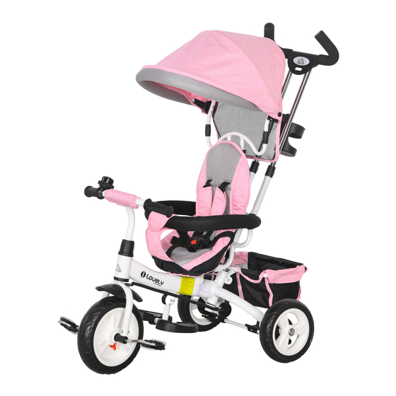
- Página 6 1.Front wheel 10.Canopy 2.Screw of Front fork 11.Feet pad 3.Front fork 12.Push bar 4.Fender 13.Cup holder 5.Main frame 14.Backrest 6.Handlebar fixing screw 15.Saddle 7.Cap of the handlebar screw 16.Rear basket 8.Handlebar 17.Rear wheel 9.Bell...
- Página 7 1. As shown in the figure: 2.As shown 3.As shown in the figure: - Insert rear wheel to the main frame. Tap picture, front - Insert the front wheel gently until the sound of click. fender onto the front fork into the front fork, tighten using screws.
- Página 8 IMPORTANT: The seat cushion is adjustable. 1 is the front file; 2 is the rear stop. The bolt holes indicated by 2 can expand the riding space 6. Insert the guardrail bracket into the seat 7. Align the seat with the frame screw hole and tube and secure it with screws.
- Página 9 Nom des pièces 1. Roue avant 10. Auvent 2. Vis de fixation de la fourche avant 11. Repose-pieds 3. Fourche avant 12. Barre de poussée 4. Garde-boue 13. Porte-gobelet 5. Cadre principal 14. Dossier 6. Vis de fixation du guidon 15.
- Página 10 Installation 1. Comme l'indique l’image : Comme l'indique Comme l'indique - Insérez les Roues arrières dans le Cadre l’image : l’image : principal. Tapotez doucement jusqu'à ce que - Visser la Garde-boue - Insérez la roue avant vous entendiez un clic. sur la Fourche avant ( dans la fourche avant, Rainure...
- Página 11 IMPORTANT : Le coussin du siège est réglable. 1 pour l'avant, 2 pour l'arrière. Les trous de boulons indiqués par 2 servent à élargir l'espace de conduite. 6. Comme indiqué dans l'image, insérez le 7. Comme indiqué dans l'image, alignez le siège support de barrière dans le tube du siège et avec les trous de vis du cadre et fixez-le avec des fixez-le avec des vis.
- Página 12 Teilebezeichnung 1. Vorderrad 10. Verdeck 2. Schraube der Vorderradgabel 11. Fußauflage 3. Vorderradgabel 12. Schiebestange 4. Schutzblech 13. Getränkehalter 5. Hauptrahmen 14. Rückenlehne 6. Lenker Befestigungsschraube 15. Sattel 7. Kappe der Lenkerschraube 16. Hinterradkorb 8. Lenker 17. Hinterrad 9. Klingel 10.
- Página 13 Aufstellung 1. Wie in der Abbildung gezeigt: 2. Wie in der Abbildung 3. Wie in der Abbildung Setzen Hinterrad gezeigt: gezeigt: Hauptrahmen ein. Vorsichtig klopfen, bis ein - Schrauben Sie das - Führen Sie das Vorder- Klickgeräusch zu hören ist. Schutzblech rad in die Vorderradgabel Vordergabel ein (Halb-...
- Página 14 WICHTIG: Das Sitzpolster ist anpassbar. 1 Ist die vordere Gang; 2 ist der hintere Gang. Die mit 2 bezeichneten Bolzenlöcher können den Sitzbereich erweitern 6. Setzen Sie die Geländerhalterung gemäß 7. Richten Sie den Sitz gemäß der Abbildung auf die der Abbildung in die Sitzrohr ein und befesti- Rahmen-Gewindebohrungen aus und befestigen gen Sie sie mit Schrauben.
- Página 15 Nome delle parti 1. Ruota anteriore 10. Tettoia 2. Vite della forcella anteriore 11. Pedana piedi 3. Forcella anteriore 12. Maniglia spingitutto 4. Parafango 13. Portabicchieri 5. Telaio principale 14. Schienale 6. Vite di fissaggio del manubrio 15. Sella 7. Cappuccio della vite del manubrio 16.
- Página 16 Installazione 1. Come mostrato in figura, inserisci l'asse 2. Come mostrato in 3. Come mostrato in della ruota posteriore nell'incavo della ruota figura, fissa il parafango figura, inserisci per prima posteriore del telaio principale, picchiettando anteriore alla forcella la testa di guida nella leggermente fino a sentirlo bloccarsi con un anteriore con le viti (la forcella anteriore e fissa-...
- Página 17 IMPORTANTE: Il cuscino del sellino è regolabile. 1 e' il livello anteriore, 2 e' il livello posteriore. I fori dei bulloni indicati con 2 offrono più lo spazio di guida. 6. Come mostrato nell'immagine, inserire il 7. Come mostrato nell'immagine, allineare il sedile supporto del parapetto nel tubo del sedile e con i fori filettati del telaio e fissarlo con le viti.
- Página 18 Nombre de las piezas 1. Rueda delantera 10. Dosel 2. Tornillo de fijación de la horquilla delantera 11. Reposapiés 3. Horquilla delantera 12. Barra de empuje 4. Guardabarros 13. Portabotellas 5. Marco principal 14. Respaldo 6. Tornillo de fijación del manillar 15.
- Página 19 Instalación 1. Como lo que se muestra en la figura: 2.Como lo que se mues- 3.Como lo que se mues- - Inserte las ruedas traseras en el marco prin- tra en la figura: tra en la figura: cipal. Golpéelas suavemente hasta que -Atornille el guardabarros - Inserta la rueda delan- escuche un “clic”.
- Página 20 IMPORTANTE: El cojín del asiento es ajustable. 1 es “delante”; 2 es “detrás”. Los orificios para tornillos indicados por 2 pueden ampliar el espacio de conducción. 6. Como se muestra en la imagen, inserte el 7. Como se muestra en la imagen, alinee el asiento soporte del guardabarros en el tubo del asien- con los agujeros roscados del marco y fíjelo con los to y fíjelo con los tornillos.


