Tabla de contenido
Publicidad
Idiomas disponibles
Idiomas disponibles
Enlaces rápidos
LOV TO ELECTRIC S.P. .
24020 GORLE (BERG MO) IT LI
VI DON E. M ZZ , 12
TEL. 035 4282111
F X (Nazionale): 035 4282200
F X (International): +39 035 4282400
L
E
E-mail info@
ovato
lectric.com
L
E
Web
www.
ovato
lectric.com
UE declaration: http://www.lovatoelectric.com/DMED330MID/DMED330MID/snp
W RNING!
– Carefully read the manual before the installation or use.
– This equipment is to be installed by qualified personnel, complying to current standards, to avoid
damages or safety hazards.
– Before any maintenance operation on the device, remove all the voltages from measuring and supply inputs and short-
circuit the CT input terminals.
– The manufacturer cannot be held responsible for electrical safety in case of improper use of the equipment.
– Products illustrated herein are subject to alteration and changes without prior notice. Technical data and descriptions
in the documentation are accurate, to the best of our knowledge, but no liabilities for errors, omissions or
contingencies arising there from are accepted.
–
circuit breaker must be included in the electrical installation of the building. It must be installed close by the
equipment and within easy reach of the operator. It must be marked as the disconnecting device of the equipment:
IEC /EN 61010-1 § 6.11.2.
– Clean the device with a soft dry cloth; do not use abrasives, liquid detergents or solvents.
TTENTION !
– Lire attentivement le manuel avant toute utilisation et installation.
– Ces appareils doivent être installés par un personnel qualifié, conformément aux normes en vigueur en
matière d'installations, afin d'éviter de causer des dommages à des personnes ou choses.
–
vant toute intervention sur l'instrument, mettre les entrées de mesure et d'alimentation hors tension et court-circuiter
les transformateurs de courant.
– Le constructeur n'assume aucune responsabilité quant à la sécurité électrique en cas d'utilisation impropre du
dispositif.
– Les produits décrits dans ce document sont susceptibles d'évoluer ou de subir des modifications à n'importe quel
moment. Les descriptions et caractéristiques techniques du catalogue ne peuvent donc avoir aucune valeur
contractuelle.
– Un interrupteur ou disjoncteur doit être inclus dans l'installation électrique du bâtiment. Celui-ci doit se trouver tout
près de l'appareil et l'opérateur doit pouvoir y accéder facilement. Il doit être marqué comme le dispositif d'interruption
de l'appareil : IEC/ EN 61010-1 § 6.11.2.
– Nettoyer l'appareil avec un chiffon doux, ne pas utiliser de produits abrasifs, détergents liquides ou solvants.
CHTUNG!
– Dieses Handbuch vor Gebrauch und Installation aufmerksam lesen.
– Zur Vermeidung von Personen- und Sachschäden dürfen diese Geräte nur von qualifiziertem
Fachpersonal und unter Befolgung der einschlägigen Vorschriften installiert werden.
– Vor jedem Eingriff am Instrument die Spannungszufuhr zu den Messeingängen trennen und die Stromwandler
kurzschlie en.
– Bei zweckwidrigem Gebrauch der Vorrichtung übernimmt der Hersteller keine Haftung für die elektrische Sicherheit.
– Die in dieser Broschüre beschriebenen Produkte können jederzeit weiterentwickelt und geändert werden. Die im
Katalog enthaltenen Beschreibungen und Daten sind daher unverbindlich und ohne Gewähr.
– In die elektrische nlage des Gebäudes ist ein usschalter oder Trennschalter einzubauen. Dieser muss sich in
unmittelbarer Nähe des Geräts befinden und vom Bediener leicht zugänglich sein. Er muss als Trennvorrichtung für das
Gerät gekennzeichnet sein: IEC/ EN 61010-1 § 6.11.2.
– Das Gerät mit einem weichen Tuch reinigen, keine Scheuermittel, Flüssigreiniger oder Lösungsmittel verwenden.
DVERTENCI
– Leer atentamente el manual antes de instalar y utilizar el regulador.
– Este dispositivo debe ser instalado por personal cualificado conforme a la normativa de instalación
vigente a fin de evitar daños personales o materiales.
–
ntes de realizar cualquier operación en el dispositivo, desconectar la corriente de las entradas de alimentación y
medida, y cortocircuitar los transformadores de corriente.
– El fabricante no se responsabilizará de la seguridad eléctrica en caso de que el dispositivo no se utilice de forma
adecuada.
– Los productos descritos en este documento se pueden actualizar o modificar en cualquier momento. Por consiguiente,
las descripciones y los datos técnicos aquí contenidos no tienen valor contractual.
– La instalación eléctrica del edificio debe disponer de un interruptor o disyuntor. Éste debe encontrarse cerca del
dispositivo, en un lugar al que el usuario pueda acceder con facilidad. demás, debe llevar el mismo marcado que el
interruptor del dispositivo (IEC/ EN 61010-1 § 6.11.2).
– Limpiar el dispositivo con un trapo suave; no utilizar productos abrasivos, detergentes líquidos ni disolventes.
UPOZORNĚNÍ
– Návod se pozorně pročtěte, než začnete regulátor instalovat a používat.
– Tato zařízení smí instalovat kvalifikovaní pracovníci v souladu s platnými předpisy a normami pro předcházení
úrazů osob či poškození věcí.
– Před jakýmkoli zásahem do přístroje odpojte měřicí a napájecí vstupy od napětí a zkratujte transformátory proudu.
– Výrobce nenese odpovědnost za elektrickou bezpečnost v případě nevhodného používání regulátoru.
– Výrobky popsané v tomto dokumentu mohou kdykoli projít úpravami či dalším vývojem. Popisy a údaje uvedené v katalogu
nemají proto žádnou smluvní hodnotu.
– Spínač či odpojovač je nutno zabudovat do elektrického rozvodu v budově. Musejí být nainstalované v těsné blízkosti přístroje a
snadno dostupné pracovníku obsluhy. Je nutno ho označit jako vypínací zařízení přístroje: IEC/ EN 61010-1 § 6.11.2.
– Přístroj čistěte měkkou utěrkou, nepoužívejte abrazivní produkty, tekutá čistidla či rozpouštědla.
AVERTIZARE!
– Citiţi cu atenţie manualul înainte de instalare sau utilizare.
– Acest echipament va fi instalat de personal calificat, în conformitate cu standardele actuale, pentru a evita
deteriorări sau pericolele.
– Înainte de efectuarea oricărei operaţiuni de întreţinere asupra dispozitivului, îndepărtaţi toate tensiunile de la intrările de
măsurare şi de alimentare şi scurtcircuitaţi bornele de intrare CT.
– Producătorul nu poate fi considerat responsabil pentru siguranţa electrică în caz de utilizare incorectă a echipamentului.
– Produsele ilustrate în prezentul sunt supuse modificărilor şi schimbărilor fără notificare anterioară. Datele tehnice şi descrierile
din documentaţie sunt precise, în măsura cunoştinţelor noastre, dar nu se acceptă nicio răspundere pentru erorile, omiterile sau
evenimentele neprevăzute care apar ca urmare a acestora.
– Trebuie inclus un disjunctor în instalaţia electrică a clădirii. Acesta trebuie instalat aproape de echipament şi într-o zonă uşor
accesibilă operatorului. Acesta trebuie marcat ca fiind dispozitivul de deconectare al echipamentului: IEC/EN 61010-1 § 6.11.2.
– Curăţaţi instrumentul cu un material textil moale şi uscat; nu utilizaţi substanţe abrazive, detergenţi lichizi sau solvenţi.
GB
THREE-PH SE ENERGY METER
WITH CT INSERTION WITH RS485 INTERF CE
Instructions manual
DME D330MID
TTENZIONE!
– Leggere attentamente il manuale prima dell'utilizzo e l'installazione.
– Questi apparecchi devono essere installati da personale qualificato, nel rispetto delle vigenti normative
impiantistiche, allo scopo di evitare danni a persone o cose.
– Prima di qualsiasi intervento sullo strumento, togliere tensione dagli ingressi di misura e di alimentazione e
cortocircuitare i trasformatori di corrente.
– Il costruttore non si assume responsabilità in merito alla sicurezza elettrica in caso di utilizzo improprio del dispositivo.
– I prodotti descritti in questo documento sono suscettibili in qualsiasi momento di evoluzioni o di modifiche. Le
descrizioni ed i dati a catalogo non possono pertanto avere alcun valore contrattuale.
– Un interruttore o disgiuntore va compreso nell'impianto elettrico dell'edificio. Esso deve trovarsi in stretta vicinanza
dell'apparecchio ed essere facilmente raggiungibile da parte dell'operatore. Deve essere marchiato come il dispositivo
di interruzione dell'apparecchio: IEC/ EN 61010-1 § 6.11.2.
– Pulire l'apparecchio con panno morbido, non usare prodotti abrasivi, detergenti liquidi o solventi.
UW G !
– Przed użyciem i instalacją urządzenia należy uważnie przeczytać niniejszą instrukcję.
– W celu uniknięcia obrażeń osób lub uszkodzenia mienia tego typu urządzenia muszą być instalowane przez
wykwalifikowany personel, zgodnie z obowiązującymi przepisami.
– Przed rozpoczęciem jakichkolwiek prac na urządzeniu należy odłączyć napięcie od wejść pomiarowych i zasilania oraz zewrzeć
zaciski przekładnika prądowego.
– Producent nie przyjmuje na siebie odpowiedzialności za bezpieczeństwo elektryczne w przypadku niewłaściwego użytkowania
urządzenia.
– Produkty opisane w niniejszym dokumencie mogą być w każdej chwili udoskonalone lub zmodyfikowane. Opisy oraz dane
katalogowe nie mogą mieć w związku z tym żadnej wartości umownej.
– W instalacji elektrycznej budynku należy uwzględnić przełącznik lub wyłącznik automatyczny. Powinien on znajdować się w
bliskim sąsiedztwie urządzenia i być łatwo osiągalny przez operatora. Musi być oznaczony jako urządzenie służące do
wyłączania urządzenia: IEC/ EN 61010-1 § 6.11.2.
– Urządzenie należy czyścić miękką szmatką, nie stosować środkow ściernych, płynnych detergentow lub rozpuszczalnikow.
ПРЕДУПРЕЖДЕНИЕ!
– Прежде чем приступать к монтажу или эксплуатации устройства, внимательно ознакомьтесь с одержанием
настоящего руководства.
– Во избежание травм или материального ущерба монтаж должен существляться только квалифицированным персоналом
в соответствии с действующими нормативами.
– Перед проведением любых работ по техническому обслуживанию устройства необходимо обесточить все
измерительные и питающие входные контакты, а также замкнуть накоротко входные контакты трансформатора тока (ТТ).
– Производитель не несет ответственность за обеспечение электробезопасности в случае ненадлежащего использования
устройства.
– Изделия, описанные в настоящем документе, в любой момент могут подвергнуться изменениям или
усовершенствованиям. Поэтому каталожные данные и описания не могут рассматриваться как действительные с точки
зрения контрактов
– Электрическая сеть здания должна быть оснащена автоматическим выключателем, который должен быть расположен
вблизи оборудования в пределах доступа оператора. Автоматический выключатель должен быть промаркирован как
отключающее устройство оборудования: IEC /EN 61010-1 § 6.11.2.
– Очистку устройства производить с помощью мягкой сухой ткани, без применения абразивных материалов, жидких
моющих средств или растворителей.
DİKKAT!
– Montaj ve kullanımdan önce bu el kitabını dikkatlice okuyunuz.
– Bu aparatlar kişilere veya nesnelere zarar verme ihtimaline karşı yürürlükte olan sistem kurma normlarına göre
kalifiye personel tarafından monte edilmelidirler
– Aparata (cihaz) herhangi bir müdahalede bulunmadan önce ölçüm girişlerindeki gerilimi kesip akım transformatörlerinede kısa
devre yaptırınız.
– Üretici aparatın hatalı kullanımından kaynaklanan elektriksel güvenliğe ait sorumluluk kabul etmez.
– Bu dokümanda tarif edilen ürünler her an evrimlere veya değişimlere açıktır. Bu sebeple katalogdaki tarif ve değerler herhangi bir
bağlayıcı değeri haiz değildir.
– Binanın elektrik sisteminde bir anahtar veya şalter bulunmalıdır. Bu anahtar veya şalter operatörün kolaylıkla ulaşabileceği yakın
bir yerde olmalıdır. Aparatı (cihaz) devreden çıkartma görevi yapan bu anahtar veya şalterin markası: IEC/ EN 61010-1 § 6.11.2.
– Aparatı (cihaz) sıvı deterjan veya solvent kullanarak yumuşak bir bez ile siliniz aşındırıcı temizlik ürünleri kullanmayınız.
G
B
1
Publicidad
Tabla de contenido

Manuales relacionados para LOVATO ELECTRIC DME D330MID


Resumen de contenidos para LOVATO ELECTRIC DME D330MID
- Página 1 LOV TO ELECTRIC S.P. . 24020 GORLE (BERG MO) IT LI VI DON E. M ZZ , 12 TEL. 035 4282111 F X (Nazionale): 035 4282200 F X (International): +39 035 4282400 DME D330MID E-mail info@ ovato lectric.com www. ovato lectric.com...
-
Página 2: Tabla De Contenido
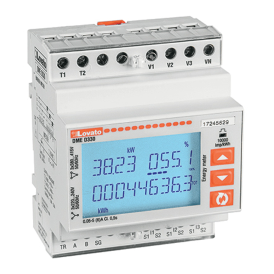
INTRODUCTION The three-phase energy meter with CT insertion, model DME D330MID, has been designed to combine the utmost ease of use with a wide range of advanced functions. Despite the extremely limited dimensions of the modular housing (just 4 modules), the energy meter features the same performance as a high-level device. The backlit LCD display permits a clear and intuitive user interface. The DME D330MID also features an isolated RS485 communication interface with Modbus protocol to permit supervision and a tariff input. -
Página 3: Displaying Measurements
– The main page displays the active power currently used in the system, the active power percentage with respect to the rated value for the system and the total active energy meter for the system. – The user can choose the page and sub-page that the DME D330MID display returns to automatically after a certain time has elapsed without the buttons being pressed. -
Página 4: Table Of Display
T BLE OF DISPL Y P GES Selection with s and t Selection with N° P GES SUB-P GES CTIVE ENERGY– CTIVE POWER kWh(TOT) – kW (TOT) – %kW with respect to the rated value IMP. CTIVE ENERGY METERS kWh+(SYS) P R T R-1 T R-2 kWh+(SYS) TOT... - Página 5 T BLE OF DISPL Y P GES Selection with s and t Selection with N° P GES SUB-P GES CTIVE POWER UNB L NCE L1-L2, L2-L3, L3-L1 FREQUENCY SYMMETRY SY(VLL) SYMMETRY SY(VLN) SYMMETRY SY(I) PH-PH VOLT GE H RM. DISTORTION THD-V(L1-L2), THD-V(L2-L3), THD-V(L3-L1) PH-N VOLT GE H RMONIC DISTORTION THD-V(L1),THD-V(L2),THD-V(L3)
-
Página 6: N Vig Ting Between The Displ Y P Ges
N VIG TING BETWEEN THE DISPL Y P GES Phase-to-phase voltages = Instantaneous value = Maximum value = Minimum value = verage value Phase-to-neutral voltages = Instantaneous value = Maximum value = Minimum value = verage value Phase and neutral currents = Instantaneous value = Maximum value = Minimum value... -
Página 7: Energy Meter Indication
HOUR COUNTER INDIC TION – If the hour counter is enabled (see menu P05), the DME D330MID displays the hour counter page, with the format indicated in the figure: – There is a total hour counter and 4 partial hour counters that can be reset and activated with different sources (see the parameters of the P05 group). -
Página 8: Limit Threshold Status Indication (Limx)
LIMIT THRESHOLD ST TUS INDIC TION (LIMx) – If the limit thresholds are enabled (see menu P08), the DME D330MID displays the page, with the corresponding status and the format indicated in the figure: – With limit threshold activated, the word ON flashes, while if it is deactivated the word OFF is constant. If no limit threshold is programmed, dashes are displayed. -
Página 9: Parameter Table
– If no buttons are pressed for two minutes, the setup menu is abandoned automatically and the system returns to the standard display without saving the parameters. – Remember that, solely for the data that can be edited using the buttons, a backup copy can be made in the DME D330MID’s EEPROM. If required, this data can be restored to the working memory. The backup and data restore commands are in the commands menu. - Página 10 M02 – UTILITY Default Range P02.01 Language English English Italiano Francais Espanol Portuguese Deutsch P02.02 High backlight level 0-100 P02.03 Low backlight level 0-50 P02.04 Low backlight delay 5-600 P02.05 Default page return OFF / 10-600 P02.06 Default pag W + kWh VL-L / VL-N …...
- Página 11 M07 – COMMUNIC TION Default Range P07.01 Serial node address 01-255 P07.02 Serial speed 9600 1200 2400 4800 9600 19200 38400 57600 115200 P07.03 Data format 8 bit – n 8 bit, no parity 8 bit, odd 8 bit, even 7 bit, odd 7 bit, even P07.04...
-
Página 12: Commands Menu
C.16 WIRING TEST dvanced Runs the test to check that the DME D330MID is connected correctly - See wiring test – Once the required command has been selected, press to execute it. The device will prompt for a confirmation. Pressing again will execute the command. -
Página 13: Remote Control
WIRING FOR PC-DME D330MID VI RS485 INTERF CE TR A TR A TR A RS485 RS485 DME D330MID n°31 DME D330MID n°1 Repeat this wiring diagram up to 255 devices TR A TR A TR A TR A TR A... -
Página 14: Technical Specifications
TECHNIC L SPECIFIC TIONS uxiliary supply Measurement and tariff power supply circuit connection Rated voltage Us 230V~ L-N / 400V~ L-L Type of terminal Screw-type (fixed) The device may operate with or without neutral Number of terminals 4 for supply / measurement Voltage range 187-264V~ L-N / 323-456V~ L-L 2 for tariff selection input... - Página 15 LOV TO ELECTRIC S.P. . 24020 GORLE (BERG MO) IT LI VI DON E. M ZZ , 12 TEL. 035 4282111 F X (Nazionale): 035 4282200 F X (International): +39 035 4282400 DME D330MID E-mail info@ ovato lectric.com www. ovato lectric.com...
- Página 16 INTRODUCCIÓN El modelo DME D330MID de contador de energía trifásico de conexión por TC está diseñado para ofrecer máxima facilidad de uso con una gran variedad de funciones avanzadas. pesar de tener una carcasa modular (solo 4 módulos) extremadamente compacta, ofrece las mismas prestaciones que los contadores de energía. La pantalla LCD retroiluminada proporciona una interface de usuario clara e intuitiva.
-
Página 17: Visu Liz Ción De Medid S
– En la página principal se muestra la potencia activa que utiliza el sistema actualmente, el porcentaje de potencia activa frente a potencia nominal del sistema y el contador de energía total activa del sistema. – El usuario puede especificar la página y la subpágina de la pantalla del contador DME D330MID que deben volver a mostrarse de forma automática cuando transcurra un tiempo sin que se pulse ninguna tecla. - Página 18 T BL DE PÁGIN S DE L P NT LL Selección con s y t Selección con N° PÁGIN S SUBPÁGIN S ENERGÍ CTIV – POTENCI CTIV kWh(TOT) – kW (TOT) – %kW frente a valor nominal CONT DORES DE ENERGÍ CTIV IMP kWh+(SYS) P R T R-1...
- Página 19 T BL DE PÁGIN S DE L P NT LL Selección con s y t Selección con N° PÁGIN S SUBPÁGIN S DESEQUILIBRIO DE POTENCI CTIV L1-L2, L2-L3, L3-L1 FRECUENCI SIMETRÍ SY(VLL) SIMETRÍ SY(VLN) SIMETRÍ SY(I) DIST. RMÓNIC DE TENSIÓN L-L THD-V(L1-L2), THD-V(L2-L3), THD-V(L3-L1) DIST.
-
Página 20: Despl Z Miento Por L S Págin S De L P Nt Ll
DESPL Z MIENTO POR L S PÁGIN S DE L P NT LL TENSIÓN ENTRE F SES = Valor instantáneo = Valor máximo = Valor mínimo = Valor medio Tensión de fase = Valor instantáneo = Valor máximo = Valor mínimo = Valor medio Corriente de fase y neutro = Valor instantáneo... -
Página 21: Indic Ción De Los Cont Dores De Energí
Tarifa 2 de energía activa importada INDIC CIÓN DEL CONT DOR HOR RIO – Si está activado (consultar el menú P05), en el contador DME D330MID aparece la página del contador horario con el formato indicado en la figura: Hora... -
Página 22: Indic Ción Del Est Do De Los Límites (Limx)
INDIC CIÓN DEL EST DO DE LOS LÍMITES (LIMx) – Si los límites están activados (consultar el menú P08), el contador DME D330MID muestra la página con el estado correspondiente y el formato indicado en la figura: Límite Límite activado desactivado Límite fuera de... -
Página 23: Descripción
– En la tabla siguiente se muestran los menús disponibles: Cód. MENÚ DESCRIPCIÓN GENER L Especificaciones del sistema UTILID DES Idioma, brillo, pantalla, etc. CONTR SEÑ ctivación de la protección de acceso INTEGR CIÓN Tiempos de integración de medidas CONT DORES HOR RIOS ctivación de los contadores horarios COMUNIC CIÓN Puerto de comunicación... - Página 24 M02 – UTILID DES Predet. Rango P02.01 Idioma English English Italiano Francais Español Portuguese Deutsch P02.02 Retroilum pantalla alta 0-100 P02.03 Retroilum pantalla de baja 0-50 P02.04 Tiempo de cambio a retroiluminación baja 5-600 P02.05 Regreso a página predeterminada OFF / 10-600 P02.06 Página predeterminada W + kWh...
- Página 25 M07 – COMUNIC CIÓN Predet. Rango P07.01 Dirección serie de nodo 01-255 P07.02 Velocidad en serie 9600 1200 2400 4800 9600 19200 38400 57600 115200 P07.03 Formato de datos 8 bits – n 8 bits, sin paridad 8 bits, impar 8 bits, par 7 bits, impar 7 bits, par...
- Página 26 C.16 PRUEB CONEXIÓN vanzado Realiza la prueba para verificar que el contador DME D330MID se ha conectado de forma correcta. Consultar el capítulo Prueba de conexión. – Una vez que se seleccione el comando deseado, pulsar para ejecutarlo. El instrumento solicitará confirmación. El comando se ejecutará cuando se vuelva a pulsar –...
-
Página 27: Control Remoto
CONEXIÓN DE ORDEN DOR CON DME D330MID MEDI NTE INTERF CE RS485 TR A TR A TR A RS485 RS485 DME D330MID n°31 DME D330MID n°1 Repeat this wiring diagram up to 255 devices TR A TR A TR A... - Página 28 C R CTERÍSTIC S TÉCNIC S limentación auxiliar Conexiones del circuito de alimentación/medida y tarificación Tensión nominal Us 230 V~ L-N / 400 V~ L-L Tipo de terminal tornillado (fijo) El dispositivo puede funcionar con o sin neutro. Número de terminales 4 para alimentación/medida Límites de funcionamiento 187-264 V~ L-N / 323-456 V~ L-L...