Tabla de contenido
Publicidad
Idiomas disponibles
Idiomas disponibles
Enlaces rápidos
Installation Instructions
LiteKeeper® 4
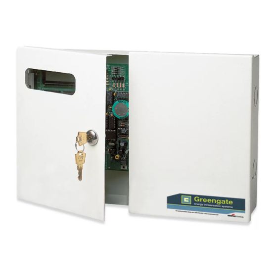
General Information
The LiteKeeper-4® is shipped in one package and
is configured with a 120V transformer or a 277V
transformer. The four relays are mounted in the high
voltage compartment. The logic board and inputs are
located in the low voltage compartment. The doors, when
shut, form a barrier between the high and the low voltage
compartments. The following information describes the
LiteKeeper 4® installation. For programming information,
refer to the LiteKeeper Keypad Programming Manual.
Getting Started
1.
Do not discard these installation instructions. Please
keep for future reference and operation information.
2.
Always disconnect all power before wiring.
3.
Use only as intended and at the listed voltage.
4.
All installation service must be performed by qualified
personnel or service technicians.
5.
Install in accordance with National Electrical Code
and any other codes that may apply.
6.
High Voltage is present inside the lighting enclosure.
Use extreme caution when performing maintenance
on this equipment. Failure to follow this warning and
use proper safety procedures could result in severe
injury or death and/or damage to the equipment.
7 .
Document all wiring that is terminated to the relays
so that the lighting control equipment can be properly
configured and programmed for operation.
8.
It is recommended that all low voltage wiring be
done with power removed to the logic board to
protect components from potential shorts during the
wiring process.
Model# LK4-120-NO
Model# LK4-277-NO
Mounting in the Enclosure
1.
Choose a dry location convenient to the circuit
breaker panel.
2.
Mount the panel on a firm surface using predrilled
holes.
3.
Connect the enclosure to the circuit breaker panel
using conduit into the punch holes provided.
4.
Remove all cuttings and dirt.
N
ote:
Make certain that high voltage and low voltage
wiring enters the enclosure separately. High
voltage wiring should be brought into the right
section of the enclosure. low voltage wire should
enter in the low voltage wiring compartment on
the left side of the enclosure.
Failure to separate high voltage from low voltage wiring
may cause interference with logic board function.
LIGHTING CONTROL
12:00 01/01/08
1
2
3
A
4
5
6
B
7
8
9
C
*
0
#
D
Low Voltage
Wiring Compartment
LK4 High Low Voltage
INS #
High Voltage
Wiring Compartment
Publicidad
Tabla de contenido

Manuales relacionados para Eaton Greengate LiteKeeper 4 LK4-120-NO


Resumen de contenidos para Eaton Greengate LiteKeeper 4 LK4-120-NO
- Página 1 Model# LK4-120-NO INS # Installation Instructions Model# LK4-277-NO LiteKeeper® 4 General Information Mounting in the Enclosure The LiteKeeper-4® is shipped in one package and Choose a dry location convenient to the circuit is configured with a 120V transformer or a 277V breaker panel.
- Página 2 Wiring the Transformer Wiring the Transformer Test branch circuits for short circuits prior to landing wiring on relays. The LiteKeeper 4® is factory configured with a 120V Connect a 120 or 277 volt, 20 amp max, de-energized transformer or a 277V transformer. The transformer voltages branch circuit breaker to the relay terminal block.
-
Página 3: Applying Power
See the recommendations support for precise limits on the number of devices the below or contact Eaton’s Cooper Controls for further logic panel can power. information. PPS5 It is recommended that power be removed from the logic board when doing initial switch input wiring. -
Página 4: Repair Information
System Reset and Clear Commands System Reset and Clear Commands Repair Information Under certain circumstances, you may want to reset the If a repair becomes necessary on your LiteKeeper 4® unit, LiteKeeper 4®. There are two different types of reset please refer all service to Greengate technical support line commands available in the LiteKeeper 4®... -
Página 5: Renseignements Généraux
Renseignements généraux Renseignements généraux ote: Assurez-vous que les câblages de haute tension et de basse tension entrent séparément dans le boîtier. Le câblage de haute tension doit passer dans la Le LiteKeeper-4MD est expédié dans une seule boîte section droite du boîtier. Le câblage de basse tension et est configuré... -
Página 6: Brancher Les Entrées De Basse Tension
Brancher les charges du relais Brancher les charges du relais Classification du relais: Câble 12 A: 10AWG Max. Remarques du relais : Le relais standard est coté pour usage avec une charge Ligne à un seul pôle. Le branchement de circuits/charges bipolaires au relais annulera la garantie de l’équipement Charge et peut entraîner des blessures sérieuses ou la mort et/... - Página 7 Câblage des commutateurs de contact d’entrée Câblage des commutateurs de contact PPS5 d’entrée Noir Cette section décrit le câblage pour les dispositifs de fermeture à contact sec. Il y a quatre bornes de câblage pour les commutateurs d’entrée sur la partie inférieure (Fil blanc) (Fil rouge) de la section de basse tension du LiteKeeper 4MD pour...
- Página 8 Commandes de réinitialisation et de suppression du système Commandes de réinitialisation et de Programmer le LiteKeeper 4 suppression du système Le LiteKeeper 4MD est programmé soit par l'interface clavier intégré ou par le logiciel de l'entreprise Keeper. Sous certaines circonstances, vous devez réinitialiser Veuillez consulter le Guide de programmation compris le LiteKeeper 4MD.
-
Página 9: Información General
Información general Información general Extraiga todos los fragmentos y suciedad. ote: Asegúrese de que los cables de alto y bajo voltaje El panel de control LiteKeeper-4® viene en un solo embalaje ingresen al recinto por separado. Los cables de y está configurado con un transformador de 120 V o 277 V. alto voltaje deben llegar a la sección derecha del Los cuatro relés vienen montados en el compartimiento recinto. -
Página 10: Conexión De Las Cargas Del Relé
Conexión de las cargas del relé Conexión de las cargas del relé Potencia del relé: Cable de 20 amperios: 10 AWG máximo. Notas sobre el relé: El relé estándar es apto para su uso con una carga de un solo polo únicamente. La conexión de circuitos/ Línea cargas de 2 polos al relé... -
Página 11: Aplicación De La Alimentación
Notas sobre el fotosensor del contacto de entrada y sobre el sensor Greengate sección de bajo voltaje del LiteKeeper 4® para permitir el PPS5 cableado de los dispositivos de cierre por contacto seco. Negro Utilice cables trenzados 18 AWG, no apantallados, para realizar el cableado de todo dispositivo de cierre por contacto seco de bajo voltaje. - Página 12 United States All trademarks are property Eaton.com of their respective owners. Eaton’s Cooper Controls Business Eaton est une marque de commerce 203 Cooper Circle déposée. Toutes les autres marques Peachtree City, GA 30269 de commerce sont la propriété de leur CooperControl.com...