Tabla de contenido
Publicidad
Idiomas disponibles
Idiomas disponibles
Enlaces rápidos
Installation Instructions
ControlKeeper 4
General Information
The ControlKeeper 4 model is shipped in one package and
is configured with either a 120V or a 277V transformer. It
is factory configured with Normally Open relays. Please
refer to your order information to determine which model
you have purchased.
Getting Started
1.
Do not discard these installation instructions. Please
keep for future reference and operation information.
2.
Always disconnect all power before wiring.
3.
Use only as intended and at the listed voltage.
4.
All installation and service must be performed by
qualified personnel or service technicians.
5.
Install in accordance with the National Electrical Code
and any other codes which may apply.
6.
Installation and wiring information contained in this
document is based on industry-accepted standards
and practices. If conflicts exist between these
instructions and any applicable codes or ordinances,
please contact Greengate before proceeding with the
installation.
7 .
High voltage is present inside the enclosure. Use
extreme caution when performing maintenance on
this equipment. Failure to follow this warning and
proper safety procedures could result in severe injury
or death, and/or damage to the equipment.
8.
Document all wiring and device terminations and
locations so that devices can be properly configured
and programmed for operation.
Mounting the Cabinet
1.
Choose a dry location on a firm surface convenient to
the circuits being controlled. Allow full clearance for
the door of the enclosure to open fully.
Model# CK4-120NO
Model# CK4-277NO
2.
Mount the ControlKeeper 4 cabinet using the
holes provided in the back of the enclosure. It is
recommended that the panel be mounted vertically.
3.
All line voltage conductors must enter the cabinet on
the right side of the enclosure.
4.
All low voltage conductors must enter the cabinet on
the left side of the enclosure.
5.
Remove all debris and metal shavings from
the enclosure before applying power to the
ControlKeeper 4.
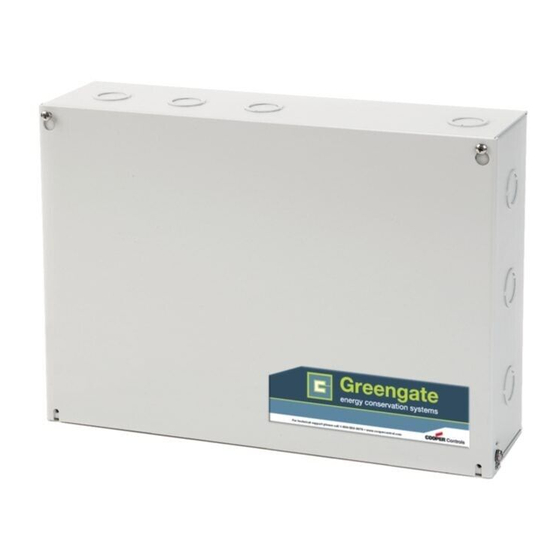
Bring low voltage in
through the Left Side
of the Enclosure
Figure 1. ControlKeeper 4 Enclosure
Power Supply Wiring
The ControlKeeper 4 is factory configured with either
a 120V or a 277V transformer. Transformer voltages are
color coded. It is recommended that a dedicated branch
circuit with circuit protection be used for power supply
wiring.
1.
Connect neutral wire to the white wire.
2.
If the transformer is a 277V model, connect orange
wire to a 277V circuit. If the transformer is a 120V
model, connect black wire to a 120V circuit.
INS #
Bring high voltage in
through the Right Side
of the Enclosure
Publicidad
Tabla de contenido

Manuales relacionados para Eaton Greengate ControlKeeper 4 CK4-120NO


Resumen de contenidos para Eaton Greengate ControlKeeper 4 CK4-120NO
- Página 1 Model# CK4-120NO INS # Installation Instructions Model# CK4-277NO ControlKeeper 4 General Information Mount the ControlKeeper 4 cabinet using the holes provided in the back of the enclosure. It is recommended that the panel be mounted vertically. The ControlKeeper 4 model is shipped in one package and is configured with either a 120V or a 277V transformer.
-
Página 2: General Information
General Information Network Wiring Notes Line=120V (Black) 277 (Orange) The ControlKeeper 4 is designed to communicate with Netural=White other ControlKeeper network panels using a lighting control RS-485 network for communications. This allows the panels to share information and to be programmed from one central location by a computer with the Keeper Enterprise Software. - Página 3 General Information making certain to observe polarity. When finished, the two end panels will have a single pair of wires coming into the network terminal block while all middle panels in the network will have two sets of wires. Network Address Switch Set the network termination jumpers.
- Página 4 General Information When powering peripheral devices such as motion additional sensors beyond the numbers listed above. These sensors and photosensors from the ControlKeeper figures do not account for additional devices such as Digital 4 panel, there may be a limitation on the number of Switches being used.
-
Página 5: Applying Power
General Information Applying Power configuration. No T-Taps/Stars should be used. The GDS-I device should reside somewhere within the daisy-chain After wiring is complete, make certain to clean panel switch net work. Total daisy-chain network length should not of all wire clippings and fragments ensuring that no exceed 1000 feet. - Página 6 General Information scheduling the hardware override switch must be in the Enterprise Software or broadcast switches and this LED AUTO or center position. See Figure 9 for location of the is flickering, ON constant, or flashing, it is an indication of hardware override switch.
-
Página 7: Repair Information
General Information Repair Information until the STATUS LED turns OFF . Once the STATUS LED turns OFF , release the reset button. The ControlKeeper 4 If a repair becomes necessary on your ControlKeeper 4 unit, unit will be reset back to factory default settings. please refer all service to Greengate’s technical support line at 1-800-553-3879. -
Página 8: Renseignements Généraux
Renseignements généraux Renseignements généraux Faire passer les fils à basse Faire passer les fils à haute tension par le côté gauche tension par le côté droit du du boîtier boîtier Le modèle ControlKeeper 4 est livré en une seule boîte et est doté... - Página 9 Renseignements généraux Branchez un disjoncteur de dérivation hors tension de Pour la meilleure performance réseau, utilisez un des câbles 120 ou 277 volts, 20A maximum à l’emplacement étiqu suggérés. Si vous n’utilisez pas le câble spécifié et que des té LINE du bornier du relais. problèmes de communication nécessitant une assistance au dépannage se présentent,des frais additionnels pour le Branchez le câble de charge à...
- Página 10 Renseignements généraux Configurez toutes les adresses des panneaux à l’aide Position de des interrupteurs DIP d’identification de réseause l'interrupteur trouvant sur chaque panneau. voir l’emplacement et les détails aux figures 6 et 7 . Au moyen de l’interrupteur de réinitialisation, effectuez une réinitialisation logicielle pour chacun des panneaux en vue d’initialiser l’adresse de chaque panneau.
- Página 11 Renseignements généraux Il est recommandé d’enlever tous les borniers de la service d’assistance technique pour les détails exacts sur carte électronique ou de couper le courant de la carte le nombre de dispositifs que le panneau de logique peut de logique lorsque vous procédez au câblage des alimenter.
- Página 12 Renseignements généraux Appliquer l’alimentation Les instructions suivantes expliquent comment connecter le dispositif GDS-I au ControlKeeper 4. Veuillez vous référer Une fois le raccordement terminé, assurez-vous de aux instructions d’installation des interrupteurs numériques libérer le panneau de tout morceaux ou fragments de fil pour obtenir de l’information sur le raccordement du réseau en vue qu’aucun fragment ne se loge entre la carte de d’interrupteurs numériques au dispositif GDS-I.
-
Página 13: La Commande De Réinitialisation Logicielle
Renseignements généraux Réseau DEL: que l’interrupteur est en position ALL ON ou ALL OFF . L ’état ON ou OFF est maintenu peu importe l’état programmé. Le Réseau DEL devrait uniquement clignoter quand Pour que les relais suivent l’ordonnancement prévu, une activité... - Página 14 Renseignements généraux La commande de suppression des paramètres: Référence de l’item Le ControlKeeper 4 est constitué d’une carte de logique Une commande qui annule les réglages est utilisée pour dotée d’une séparation transparente entre les composantes effacer la programmation du dispositif ControlKeeper 4. Elle de basse tension et celles de tension composée.
-
Página 15: Información General
Información general Información general Haga ingresar los cables de Haga ingresar los cables de bajo voltaje a través del lado alto voltaje a través del lado izquierdo del alojamiento derecho del alojamiento El modelo ControlKeeper 4 se envía en un paquete y está configurado con un transformador de 120V o de 277V. - Página 16 Información general Conecte un disyuntor de circuito de rama Para un mejor funcionamiento de la red, se debería utilizar desenergizado de 120 o 277 voltios y 20 amperios uno de los cables sugeridos. Si no se utiliza el cable como máximo, a la posición del bloque de terminales especificado y se produjeran problemas de comunicación del relé...
- Página 17 Información general En los paneles medios de la red, quite los puentes de Posición del terminación de la red. interruptor Establezca todas las direcciones del panel usando los interruptores DIP de identificación de la red del panel en cada uno de los paneles. Consulte las Figuras 5 y 6 para ver la ubicación y los detalles.
-
Página 18: Cableado Del Interruptor Digital
Información general Se recomienda quitar los bloques de terminales de la placa o interrumpir la alimentación de la placa lógica cuando realice el cableado de entrada del interruptor por primera vez. Cableado del interruptor de la entrada de contacto En esta sección se describe el cableado de los dispositivos de cierre por contacto seco. -
Página 19: Aplicación De La Alimentación
Información general Las siguientes instrucciones describen la conexión Encienda la unidad. Se recomienda eliminar toda la del dispositivo GDS-I al ControlKeeper 4. Consulte las programación de la unidad, a menos que la hayan instrucciones de instalación del interruptor digital para enviado previamente programada de fábrica. -
Página 20: Led Del Interruptor Digital
Información general Operación del LED cable de la red que puede interferir con el funcionamiento correcto del sistema. Revise todos los cables de la red con El ControlKeeper-4 tiene indicadores LED para el control de atención para ver que no haya cortocircuitos en el cable estado. -
Página 21: Programación Del Controlkeeper
Información general Referencia de elementos iluminación. Para reprogramar la unidad, deberá utilizar el software Keeper Enterprise. Para ejecutar un Comando de El ControlKeeper 4 consiste en una placa lógica con una eliminación, presione y mantenga presionado el botón de separación clara de la tensión de línea y los componentes reinicio ubicado en la esquina infrior derecha de la sección de bajo voltaje. - Página 24 WARRANTIES AND LIMITATION OF LIABILITY Please refer to www.cooperlighting.com under the Legal section for our terms and conditions. GARANTIES ET LIMITATIONS DE RESPONSABILITÉ LÉGALE Veuillez consulter la section juridique de www.cooperlighting.com pour connaître nos conditions générales GARANTÍAS Y LIMITACIONES DE RESPONSABILIDAD CIVIL Remítase a la sección Legal del sitio web www.cooperlighting.com para conocer nuestros términos y condiciones.