Publicidad
Idiomas disponibles
Idiomas disponibles
Enlaces rápidos
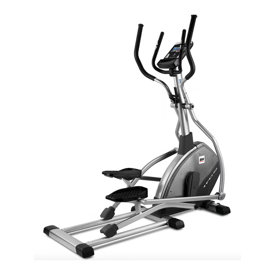
G855i-G855TFT
Instrucciones de montaje y utilización
Instructions for assembly and use
Instructions de montage et utilisation
Montage und gebrauchsanleitung
Instruções de montagem e utilização
Istruzioni di montaggio e uso
Montage-en gebruiksinstrukties
Publicidad

Manuales relacionados para BH FITNESS G855i


Resumen de contenidos para BH FITNESS G855i
- Página 1 G855i-G855TFT Instrucciones de montaje y utilización Instructions for assembly and use Instructions de montage et utilisation Montage und gebrauchsanleitung Instruções de montagem e utilização Istruzioni di montaggio e uso Montage-en gebruiksinstrukties...
- Página 2 Fig 0...
- Página 3 Fig.1...
- Página 4 Fig.2 Fig.3...
- Página 5 Fig.4 Fig.5...
- Página 6 Fig.6 Fig.7...
- Página 7 Fig.8 Fig.9 Fig.10...
- Página 8 Fig.11 Fig.12 Fig.13 Fig.14...
-
Página 9: Trabaje En El Nivel De Ejercicio
Español INSTRUCCIONES DE con las instrucciones. Si encuentra algún componente defectuoso durante SEGURIDAD.- montaje comprobación Antes comenzar cualquier aparato, o si oye algún ruido extraño programa de ejercicio, consulte a su durante la utilización, pare. médico. Se recomienda la realización No utilice este aparato hasta que se de un examen físico completo. -
Página 10: Los Padres Y Otras Personas
Es muy importante mantener un ritmo de calentamiento y relajación de constante. El ritmo de ejercicio será lo costumbre, pero cuando esté llegando bastante alto para aumentar al final de la fase de ejercicio, pulsaciones hasta la zona objetivo aumente la resistencia para someter muestra gráfico sus piernas a un mayor esfuerzo. - Página 11 6 Utilice prendas de vestir y calzado (114) Casquillo de mastil. adecuado. Átese cordones (116) Tornillo de M-8x25. correctamente. (117) Tornillo de M-8x15. (118) Arandela muelle de M-8. 1. INSTRUCCIONES DE (119) Arandela curva de M-8. MONTAJE.- (120) Tornillo hex. M-8x15. (121) Arandela plana de M-8.
- Página 12 Acerque el tubo de remo (87) al tubo Realice el mismo montaje con el saliente del cuerpo central (51), Fig.4, apoyapiés derecho (97) marcado con conexione los terminales (1 con el 2) la letra (R) y el reposapies (6) Fig.5. Fig.4.
- Página 13 7. MONTAJE DEL TIRANTE 9. COLOCACIÓN DEL DE PIES.- MANILLAR.- Coja el tirante del pie (77) y posiciónelo Posicione el manillar (88) en el tubo con el brazo inferior (85), como le de manillar (87), Fig.9, introduzca el muestra la Fig.8, haciendo coincidir los cable del hand-grip (5) por la ranura agujeros.
- Página 14 MOVIMIENTO Y CONEXIÓN A LA RED.- ALMACENADO.- Introduzca la clavija (m) de enganche del transformador en el punto de La unidad está equipada con ruedas conexión (k), del cuerpo central, (parte (68) como muestra la Fig.13 lo que trasera inferior) Fig.14 y conecte el hace más sencillo su movimiento.
- Página 15 English SAFETY INSTRUCTIONS.- If you discover any defective component while assembling or checking the Consult your doctor before starting any equipment, or if you hear any strange exercise program. It is advisable to noise during exercise then stop. Do not undergo complete physical...
- Página 16 Weight loss In this case the important factor is the effort made. The more intense and the longer the session, the greater the number of calories burned. Even though you are dong the same work as you do to improve fitness, the objective has changed.
- Página 17 1. ASSEMBLY INSTRUCTIONS.- (123) Screw M-6x31. (124) Screw M-6x12. 1. Take the unit out of its box and make (125) Screw M-5x15. sure that all of the pieces are there: (126) Auto screw M-5x15. (127) Screw M-5x10. ATTENTION: The assistance of a Allen spanner n4, n5, n6, second person is recommended Double ended ring spanner.13-17...
- Página 18 4. FITTING THE FOOT BARS.- 6. FITTING THE FOCUS BARS.- Then fit take the left foot (77) (marked Insert the left focus bar (85) (marked with the letter “L”) and insert the end with the letter “L”) onto the focus bar bush onto the drive spindle (E) on the spindle Fig.7,with the bushing (114) main body (51) Fig.4 with washers...
- Página 19 8. FITTING THE UPPER Fig.10, making sure not to pinch the wires. FOCUS BARS.- Use supplied screws to hold the Once you have assembled the top focus monitor in place, Fig.10. bars, take the lower focus bar (93) (marked with the letter “L”) and insert it LEVELLING.- onto the boss for the top bar (85), Once the unit has been placed into its...
- Página 20 Français CONSIGNES DE SÉCURITÉ.- qu’un élément est défectueux ou si vous entendez bruit étrange Avant de commencer tout exercice, durantl’utilisation, ne pas utiliser la demandez l’avis de votre médecin. Il machine avant d’avoir résout est conseillé de passer un examen problème.
- Página 21 Il est très important de maintenir un physique en général, vous devrez rythme constant. rythme modifier votre programme l’exercice sera suffisamment élevé d’entraînement. Faites les exercices pour augmenter les pulsations jusqu’à d’échauffement relaxation zone-objectif indiquée habituels et à la fin de phase de schéma suivant.
- Página 22 5 Seule une personne à la fois peut monter sur l’appareil. 6 L’utilisateur de l’appareil doit porter Fig.2 Visserie des vêtements et des chaussures (110) Bouchon appropriés pour réaliser l’exercice. (111) Rondelle Tube M8. (113) Rondelle D38. 1. MONTAGE.- (114) Douille tube. Déballez l’appareil et vérifiez qu’il ne (116) Vis M-8x25.
- Página 23 3. MONTAGE DU TUBE Ensuite, placez le caoutchouc (3) et le fixer avec des vis (126). RAMEUR.- Faire de même pour le repose-pieds Prendre le tube rameur (87) et droit (97) signalé par la lettre (R) dans introduire carcasse cache le soutien repose pied droit.
- Página 24 7. MONTAGE DU TIRANT DES faire sortir par la partie supérieure du guidon. PIEDS .- Poser les vis (122) Fig.9 et visser Prendre le tirant du pied (77) et le solidement, placez ensuite le couvercle placer avec le bras inférieur (85) de protection de la bride (107).
- Página 25 DÉPLACEMENT ET BRANCHEMLENT AU RANGEMENT.- COURANT.- Comme indiqué dans la Fig.13, cet Introduisez fiche appareil dispose de roulettes (68) qui branchement du transformateur dans le permettent un déplacement facile. Ces point de connexion (k) du corps central roulettes sont posées sur la partie (partie arrière inférieur) Fig.14 et avant de l’appareil et permettent d’e le connectez le transformateur (109) de...
- Página 26 Deutsch SICHERHEITSHINWEISE.- montiert haben. Nutzen Gerät stets Bevor einem entsprechend der Anleitung. Sollten Sie Trainingsprogramme beginnen, bei der Montage oderÜberprüfung des konsultieren Sie bitte Ihren Arzt. Wir Geräts feststellen, dass eine empfehlen dabei eine komplette Komponente defektist oder sollte Untersuchung. während Benutzung Arbeiten Sie mit dem empfohlenen...
- Página 27 2. Trainingsphase Möglicherweise müssen sie dabei die dieser Phase wird erfolgt Dauer des Trainings reduzieren. Wenn hauptsächliche physische Anstren- Sie darüber hinaus Ihre allgemeine gung. Nach dem regelmäßigen Training physische Form verbessern wollen, wird dei Flexibilität der Beinmuskulatur müssen Sie Ihr Trainingsprogramm gesteigert.
- Página 28 4 Der Eigentümer hat die Aufgabe Fig.2 Schrauben sicherzustellen, dass alle Benutzer des (110) Buchsen. Geräts über alle notwendigen (111) UnterlegscheibenM8. Sicherheitsmaßnahmen informiert sind (113) Unterlegscheiben D38. und sich ents- prechend verhalten. (114) Hülse. 5 Das Gerät darf nicht von mehrere (116) Inbusschraube M-8x25.
- Página 29 3. MONTAGE DES 5. MONTAGE DER RUDERROHRS.- FUSSSCHALEN.- Führen Sie das Ruderrohr (87) in Setzen Sie die Achse der linken, mit Pfeilrichtung untere Buchstaben markierten Ziergehäuse (105) ein. Fußschale (102) auf Unterstützung Führen Sie das Ruderrohr (87) an das Linke Trittfläche.(4). Dann legen Sie die aus dem Hauptrahmen (51) tretende Gummi-(3)
- Página 30 6. MONTAGE DER ARME.- 8. MONTAGE DER OBEREN Setzen Sie den linken Arm (85) (mit ARME.- dem Buchstaben L gekennzeichnet) in Wenn die Arme montiert sind, nehmen die Drehachse der Arme Fig.7; mit die Sie den oberen linken Arm (93) (er ist Hülse (117) flachen...
- Página 31 11.- MONTAGE DES Geräts. Mit ihrer Hilfe können Sie das Gerät bequemer zu dem gewünschten MONITORS.- Standort transportieren. Heben Sie es Verbinden Sie die aus dem Lenkerrohr dazu auf der Rückseite leicht an. (87) kommenden Klemmen (5) (1) mit Bewahren Sie das Gerät an einem den Klemmen des Monotors (103) trockenen Ort mit möglichst geringen Fig.10.
- Página 32 Português INSTRUÇÕES DE Utilize o aparelho sempre de acordo com as instruções. Se encontrar algum SEGURANÇA.- componente com defeito durante a Antes de começar qualquer programa montagem ou durante a comprovação de exercício, consulte o seu médico. do aparelho,Xou se ouvir algum ruído Recomendamos a realização de um estranho durante a utilização, pare.
- Página 33 O ritmo do exercício deverá ser o exercício, aumente a resistência para suficientemente alto forma submeter as suas pernas a um maior aumentar as pulsações até à zona esforço. Deverá reduzir a velocidade objectivo que se mostra no seguinte para manter o ritmo cardíaco na zona gráfico.
- Página 34 INSTRUÇÕES DE MONTAGEM.- (119) Arandela de M-8. (120) Parafusos de. M-8x15. 1 Retire a unidade da caixa e (121) Arandela plana de M-8. comprove se estão todas as peças. (122) Parafusos de M-8x20. (123) Parafusos de M-6x31. ATENÇÃO: Recomenda-se a ajuda (124) Parafusos de M-6x12.
- Página 35 3. MONTAGEM DO TUBO (122). Em seguida, coloque a borracha (3) e fixe com parafusos (126). REMO.- Realize a mesma montagem com o Pegue no tubo de remo (87) e apoio de pés direito (97) marcado com introduza a carcaça embelezadora a letra (R) na soporte Apoio de pés inferior de remo (105).
- Página 36 7. MONTAGEM DA FAIXA Coloque os parafusos (122) Fig.9 e aperte com força, coloque a tampa DOS PÉS.- protecção do grampo (107). Pegue na faixa dos pés (77) e posicione-o com o braço inferior (85), 10. MONTAGEM DO PORTA- como mostra a Fig.8, fazendo coincidir GARRAFAS.- os orifícios.
- Página 37 LIGAÇÃO À REDE.- Para qualquier consulta, não hesite em contactar com o S.A.T - Serviço de Introduza a cavilha (m) de engate do Assistência Técnica - , telefonando transformador no ponto de conexão, do para o serviço de apoio ao cliente (ver corpo central (k),...
- Página 38 Italiano ISTRUZIONI DI SICUREZZA.- difettoso durante il montaggio o verifica dell’ apparecchio, o se sente qualche Prima cominciare qualsiasi rumore strano durante il suo utilizzo, programma d’ allenamento, chieda fermi la macchina. Non usi questo consulenza medica. Si consiglia di apparecchio fino a che non abbia risolto realizzare un controllo fisico completo.
- Página 39 È molto importante mantenere un peró quando sia vicina alla fine della ritmo constante. ritmo dell’ fase d’ allenamento, aumenti allenamento sarà alto a sufficienza per resistenza per sottomettere le sue fare in modo che aumentino le gambe ad uno sforzo maggiore. Dovrà pulsazioni fino alla zona obiettivo che ridurre la velocità...
-
Página 40: Istruzioni Di Montaggio
ISTRUZIONI DI MONTAGGIO (117) Vite c/ cresta M-8x15. (118) Rondelle a molla M-8. 1. Estragga l’ apparecchio dalla scatola (119) Rondella de M-8. e verifi chi di avere a disposizione tutti i (120) Vite c/ cresta M-8x15. pezzi. (121) Rondella piana M-8. (122) Vite c/ cresta M-8x20. - Página 41 Inserire il tubo remo (87) nel tubo Poi, prendi la piastra d'appoggio del uscente, del corpo centrale (51) nel poggiapiedi (115) e avvitarla nel foro verso della freccia, Fig.4, facendo centrale con le viti (117) le rondelle a attenzione a non prendere i cavi. molla (118) e la rondella piatta (121), Inserire le viti (117) con le rondelle successivamente avvitare i fori degli...
- Página 42 7. REGOLAZIONE DEL 9. COLLOCAZIONE DEL TIRANTE DEI PIEDI.- MANUBRIO.- Prendere il tirante del piede (77) e Collochi il manubrio (88) nel tubo del posizionarlo con il braccio inferiore manubrio (87), Fig.9, introduca il cavo (85), come indica la Fig.8, facendo del hand-grip (5) nel foro come coincidere i fori.
- Página 43 SPOSTAMENTO ED COLLEGAMENTO ALLA RETE IMMAGAZZINAGGIO.- ELETTRICA.- L’ apparecchio è munito di ruote (68) Introduca la spina (m) d’ aggancio del che rendono più semplice il suo trasformatore punto spostamento. Le ruote che si trovano collegamento, del corpo centrale (k), nella parte anteriore...
- Página 44 Nederlands VEILIGHEIDSAANWIJZINGEN Als u tijdens het monteren een defect onderdeelvindt of als u tijdens de Raadpleeg uw geneesheer alvorens u werking van het toestel een vreemd met een oefeningenprogramma begint. geluid hoort, stop dan onmiddellijk. Het wordt aangeraden om een volledig Gebruik het toestel niet opnieuw totdat onderzoek te laten doen.
- Página 45 Het ritme van de oefening dient gewoonlijk, maar wanneer u aan het voldoende hoog te liggen om de einde van de oefening komt, vermeerdert polsslag in de zone te krijgen die in de u de weerstand om zo een grotere onderstaande grafiek is aangegeven.
- Página 46 MONTAGE-INSTRUCTIES.- (121) Platte ring M-8. (122) Inbusschroef M-8x20. 1 Haal het apparaat uit de verpakking (123) Inbusschroef M-6x31. controleer alle onderdelen (124) Inbusschroef M-6x12. aanwezig zijn. (125) Inbusschroef M-5x15. N.B.: De hulp van een tweede persoon (126) Inbusschroef M-5x15. wordt aanbevolen bij het monteren van (127) Inbusschroef M-5x10.
- Página 47 Bevestig opnieuw de schroeven (117), sluitring (118) en de vlakke sluitring de sluitringen (119) en de verende (121). Bevestig vervolgens sluitringen (118), Fig.4, en maak alles schroeven (117) de verende sluitringen goed vast. (118) en de vlakke sluitringen (121) in Laat de onderkantbedekking (105) de gaten aan de randen van de plaat.
- Página 48 Voer vervolgens de bout (117) met de monitor (103) stekende uiteinde aan, verende sluitring (118) en de vlakke Fig.10. sluitring (121) en draai. Plaats de monitor (103) bovenop de Als u voelt de voetsteun heeft losheid, plaat op de hoofdstang (87), zoals volgt te werk: weergegeven in Fig.10, ervoor zorgend - Verwijder de bout.
- Página 49 AANSLUITING Als u twijfels hebt over enig onderdeel van dit toestel, aarzel dan niet contact ELEKTRICITEITSNET.- op te nemen met de technische Steek de verbindingsstekker (m) van bijstandsdienst door dienstverlening te de transformator in het aansluitpunt, bellen (zie laatste pagina van de van het centrale frame(k), (achterkant handleiding).
- Página 50 G855i...
- Página 52 Para pedido de repuesto: Indicar el código de la pieza y la cantidad To order replacement parts: State the part code and Quantity Pour toute commande pièces détachées: Indiquer le code de la pièce et la quantité Bestellung von Ersatzteilen: Bitte angeben Teil-code und Menge Para encomenda de peça de recambio: Indicar o código da peça ea quantidade Per ordinare pezzi di ricambio: Indicare il codice del pezzo e la quantità...
- Página 53 G855TFT...
- Página 55 Para pedido de repuesto: Indicar el código de la pieza y la cantidad To order replacement parts: State the part code and Quantity Pour toute commande pièces détachées: Indiquer le code de la pièce et la quantité Bestellung von Ersatzteilen: Bitte angeben Teil-code und Menge Para encomenda de peça de recambio: Indicar o código da peça ea quantidade Per ordinare pezzi di ricambio: Indicare il codice del pezzo e la quantità...
- Página 56 Español Por medio de la presente Exercycle S.L. declara que este producto cumple con los requisitos esenciales y cualesquiera otras disposiciones aplicables o exigibles de las Directivas 2009/125/CE, 2011/65/CE, 2014/30/CE y 2014/35/CE. Hereby, Exercycle S.L, declares that this product is in compliance with the English essential requirements and other relevant provisions of Directives 2005/32/EC, 2011/65/EC, 2014/30/EC and 2014/35/EC.
- Página 57 Tel.: +351 234 729 510 902 170 258 Fax: +351 234 729 519 Fax: +34 945 56 05 27 e-mail: info@bhfitness.pt e-mail: sat@bhfitness.com BH FITNESS NORTH AMERICA BH FITNESS MEXICO BH FITNESS UK 20155 Ellipse BH Exercycle de México S.A. de Tel: 02037347554...