Publicidad
Idiomas disponibles
Idiomas disponibles
Enlaces rápidos
This manual is intended as a quick reference installation guide. Please refer to the control panel
manufacturers installation manual for detailed system information
GENERAL INFORMATION
The M200 series of modules are a family of microprocessor controlled interface devices permitting
the monitoring and/or control of auxiliary devices.
SPECIFICATIONS
Operating Voltage Range
Maximum Standby Current
No Communications
Communication with LED enabled
LED Current (Red)
LED Current (Yellow)
Operating Temperature
Humidity
Module Dimensions
Surface Mount Box Dimensions
Weight (Module Only)
Weight (Module and M200E-SMB)
Maximum Wire Gauge
INSTALLATION
Note:
These modules must only be connected to control panels using compatible proprietary
analogue addressable communication protocols for monitoring and control.
M200 series modules can be mounted in several ways (See figure 1):
1.
An M200E-SMB custom low profile surface-mounting box.
2.
An M200E-DIN Adaptor allows mounting onto standard 35mm x 7.5mm "Top Hat" DIN rail.
3.
An M200E-PMB Panel Mount Bracket allows the module to be mounted directly into a panel.
Wiring to all series M200 modules is via plug in type terminals capable of supporting conductors up
to 2.5mm²
Disconnect loop power before installing modules or sensors
The module address is selected by means of rotary decade address switches (see figure 2). These
can be accessed either from the front or the top of the module. A screwdriver should be used to
rotate the wheels to select the desired address, either from the front, or the top of the module.
Short Circuit Isolators
All M200 series modules are provided with short circuit monitoring and isolators on the intelligent
loop. If required the isolators may be wired out of the loop to facilitate the use of the modules on high
current loaded loops, for example if sounders are used. To achieve this, the loop out positive should
be wired to terminal 5 rather than terminal 2. See the relevant wiring diagram for details.
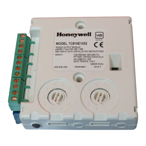
TC810E1032 SINGLE CHANNEL OUTPUT MODULE
The TC810E1032 output module allows the control of auxiliary devices such as fire shutters or
sounders.
A single tri-colour LED indicates the status of the module. In normal conditions, the LED can be set
by command from the control panel to blink green when the module is polled. When the control panel
switches the relay to the energised state the LED can be set to continuous green. In the case of an
open circuit or fault on the output circuit, the module will set the LED to blink yellow.
TC810E1032 Wiring
The TC810E1032 can be wired for either supervised or non-supervised operation - see figures 3 and
4 overleaf respectively. If using the VdS optional polarised resistor EOL device, part no. M200E-EOL-
RD, note that the EOL device red wire connects to terminal 8 and the grey wire to terminal 9, as
monitoring voltages are reversed.
When the module is used in supervised mode and power is supplied to the module, a switched
negative input on terminal 12 can be used to signal an external fault condition, such as a power
supply fault. Loss of power is also supervised in this mode such that if the supply voltage falls below
7V a fault indication is achievable. Note that the use of this fault mode is dependant on panel software.
Please contact the panel manufacturer for further details.
Electrostatic Sensitive Device
Observe precautions when handling and making connections
FIGURE 1: MODULE MOUNTING METHODS
M200E-SMB Surface Mount Box
Cover
Module
Base Box
Surface Mount Box Base is affixed to
mounting surface, and then the module
and cover are screwed onto the base
using the two screws supplied.
M200E-PMB Panel Mount Bracket
Adaptor bracket is mounted directly into panel using 2
x M4 Pan head screws.
Module is pushed into adaptor until it clips into place.
H200-94-00
INSTALLATION INSTRUCTIONS
FOR TC810E1032 OUTPUT MODULE
15 to 30VDC (Min 17.5VDC to ensure LED
operation)
310µA
510µA
2.2mA
8.8mA
-20°C to 60°C
5% to 95% Relative Humidity
93mm(H) x 94mm(W) x 23mm(D)
132mm(H) x 137mm(W) x 40mm(D)
85 g
227 g
2.5mm²
CAUTION
CAUTION
M200E-DIN DIN Rail Bracket
Top
Bottom
Push Module into adaptor Bracket until it clips into
place.
Locate top clip over DIN rail and rotate bottom down
to clip into place.
To Remove, lift up, then rotate top away from the rail.
Pittway Tecnologica SpA, Via Caboto 19/3, 34147 TRIESTE, Italy
FIGURE 2: ROTARY DECADE
ADDRESS SWITCHES
Table 1: EOL Monitoring Options
Mode
Switch A
Position
Std
0
VdS
1
RLY
N/A
FIGURE 3: TC810E1032 SINGLE OUTPUT MODULE
WITH SUPERVISED OUTPUT
-
LOOP OUTPUT
+
LOOP OUTPUT
-
LOOP INPUT
+
LOOP INPUT
+
LOOP OUTPUT (SEE NOTES 1)
SEE NOTE 2
-
+
+
-
EXTERNAL POWER
SUPPLY MAXIMUM 32VDC,
MINIMUM 7VDC
EOL
SEE NOTE 3
M200E-EOL-R
SEE NOTE 5 AND TABLE 1
Notes:
1
If short circuit isolation is not required, loop output+ should be wired to terminal 5 and not 2.
Terminal 5 is internally connected to terminal 4.
2
To enable output circuit supervision, the link supplied must be fitted across terminals 6 and
7, and the load must be polarised.
3
In supervised mode, the module monitors the power supply voltage across terminals 10 and
11 to ensure it does not drop below 7V, and also monitors for a switched negative fault signal
from the power supply to terminal 12 (optional). If a fault is seen the yellow LED will blink,
and a fault may be indicated at the panel. The use of these fault warnings is dependant on
panel software; please refer to your panel supplier.
4
Up to 1.5A load can be driven subject to the supply capability, total cable resistance and
minimum voltage required by the load.
5
An alternative end of line monitoring option, part number M200E-EOL-RD is available for
VdS 2489 requirements, see table 1. Maximum cable series resistance is 10W so max.
load current is limited by permissible voltage drop along the cable, min. PSU voltage and
min. load voltage requirement.
eg: Min PSU voltage = 21V, min load voltage = 18V, max. series resistance = 10Ω,
therefore max. current = 300mA [(21-18)/10 Amps.]
FIGURE 4: TC810E1032 SINGLE OUTPUT MODULE
WITH UNSUPERVISED OUTPUT
-
LOOP OUTPUT
+
LOOP OUTPUT
-
LOOP INPUT
+
LOOP INPUT
+
LOOP OUTPUT (SEE NOTE 1)
{
NC
Relay Contact
C
Rating:
30VDC, 2A or
30VAC, 0.5A
NO
resistive load
Notes:
1
If short circuit isolation is not required, loop output+ should be wired to terminal 5 and not 2.
Terminal 5 is internally connected to terminal 4.
Warning:
When switching inductive loads, in order to
protect the module from surges caused by
back emf as the load is switched, it is
important to protect the relay contacts.
A diode with a reverse breakdown voltage of
at least ten times the circuit voltage (dc
applications only), or a varistor (ac or dc
applications) should be connected across the
load.
1
Switch B
EOL Device
Load
Position
0
See Fig 3,
47kΩ Resistor
Note 4
M200E-EOL-R
0
See Fig 3,
Polarised 47Ω
Note 5
M200E-EOL-RD
1
Unsupervised
TC810E1032
A
x10
B
SEE NOTE 5 AND TABLE 1
TC810E1032
4
5
3
6
2
7
2
1
8
0
9
A
x10
B
Contact
+
A B
1
0
x1
C
A B
1
0
4
5
3
6
7
1
8
0
9
x1
C
Diode
(dc only)
or
Varistor
I56-2104-000
Publicidad

Manuales relacionados para Honeywell TC810E1032


Resumen de contenidos para Honeywell TC810E1032
- Página 1 TC810E1032 Wiring Up to 1.5A load can be driven subject to the supply capability, total cable resistance and The TC810E1032 can be wired for either supervised or non-supervised operation - see figures 3 and minimum voltage required by the load.
- Página 2 Un dispositivo di file linea opzionale, codice M200E-EOL-RD, è adatto ad incontrare i È possibile cablare il modello TC810E1032 affinché funzioni in modalità di supervisione o di non requisiti VdS 2489, vedi tabella 1. La resistenza massima in serie dei cavi è di 10W quindi supervisione - ved.
- Página 3 Por ejemplo: Tensión mínima de alimentación = 21 V, tensión de carga mínima = 18 V, El TC810E1032 se puede conectar para que funcione con o sin supervisión (consulte las figuras 3 y resistencia en serie máxima = 10Ω, por lo tanto la corriente máxima = 300 mA [(21-18)/10 A].
- Página 4 Baugruppe wird durch den Leitungswiderstand von zulässigen max. 10Ohm und dem Spannungsabfall auf der Leitung zwischen Netzteil und Verbraucher begrenzt. BEISPIEL: Das Modul TC810E1032 kann für den überwachten oder nicht überwachten Betrieb verdrahtet Min Netzteilspannung = 21V, min. Spannung am Verbraucher = 18V, max.