Tabla de contenido
Publicidad
Idiomas disponibles
Idiomas disponibles
Enlaces rápidos
Safe Operation Practices • Set-Up • Operation • Maintenance • Service • Troubleshooting • Warranty
O
'
M
peratOr
s
anual
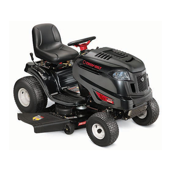
Hydrostatic Lawn Tractor — Horse
WARNING
READ AND FOLLOW ALL SAFETY RULES AND INSTRUCTIONS IN THIS MANUAL
BEFORE ATTEMPTING TO OPERATE THIS MACHINE.
FAILURE TO COMPLY WITH THESE INSTRUCTIONS MAY RESULT IN PERSONAL INJURY.
TROY-BILT, P.O. BOX 361131 CLEVELAND, OHIO 44136-0019
Printed In USA
Form No. 769-07569
(November 1, 2011)
Publicidad
Capítulos
Tabla de contenido
Solución de problemas

Manuales relacionados para Troy-Bilt Horse


Resumen de contenidos para Troy-Bilt Horse
- Página 1 READ AND FOLLOW ALL SAFETY RULES AND INSTRUCTIONS IN THIS MANUAL BEFORE ATTEMPTING TO OPERATE THIS MACHINE. FAILURE TO COMPLY WITH THESE INSTRUCTIONS MAY RESULT IN PERSONAL INJURY. TROY-BILT, P.O. BOX 361131 CLEVELAND, OHIO 44136-0019 Printed In USA Form No. 769-07569...
-
Página 2: Tabla De Contenido
Visit us on the web at www.troybilt.com See How-to Maintenance and Parts Installation Videos at www.troybilt.com/tutorials ◊ Call a Customer Support Representative at (800) 828-5500 or (330) 558-7220 ◊ Write us at Troy-Bilt • P.O. Box 361131 • Cleveland, OH • 44136-0019... -
Página 3: Safe Operation Practices
Important Safe Operation Practices WARNING! This symbol points out important safety instructions which, if not followed, could endanger the personal safety and/or property of yourself and others. Read and follow all instructions in this manual before attempting to operate this machine. Failure to comply with these instructions may result in personal injury. - Página 4 Slope Operation A missing or damaged discharge cover can cause blade contact or thrown object injuries. Slopes are a major factor related to loss of control and tip-over Stop the blade(s) when crossing gravel drives, walks, or accidents which can result in severe injury or death. All slopes roads and while not cutting grass.
- Página 5 Children Service Tragic accidents can occur if the operator is not alert to the Safe Handling of Gasoline: presence of children. Children are often attracted to the machine and the mowing activity. They do not understand To avoid personal injury or property damage use extreme the dangers.
-
Página 6: Spark Arrestor
Do not modify engine Periodically check to make sure the blades come to complete stop within approximately (5) five seconds after To avoid serious injury or death, do not modify engine in any operating the blade disengagement control. If the blades way. - Página 7 Safety Symbols This page depicts and describes safety symbols that may appear on this product. Read, understand, and follow all instructions on the machine before attempting to assemble and operate. Symbol Description READ THE OPERATOR’S MANUAL(S) Read, understand, and follow all instructions in the manual(s) before attempting to assemble and operate DANGER—...
- Página 8 2 — i ection mportant peration racticeS...
-
Página 9: Assembly & Set-Up
Assembly & Set-Up Assembly & Set-Up Tractor Set-Up Shipping Brace Removal WARNING! Make sure the riding mower’s engine is Connecting the Battery Cables off, remove the ignition key, and set the parking brake before removing the shipping brace. Refer to CALIFORNIA PROPOSITION 65 WARNING the Controls and Features section for instructions on Battery posts, terminals, and related accessories... - Página 10 Attaching The Steering Wheel If the steering wheel for your tractor did not come attached, the hardware for attaching it has been packed within the steering wheel, beneath the steering wheel cap. Carefully pry off the steering wheel cap and remove the hardware. With the wheels of the tractor pointing straight forward, place the steering wheel over the steering shaft.
-
Página 11: Important
Setting the Deck Gauge Wheels (if so equipped) • Gasohol (up to 10% ethyl alcohol, 90% unleaded gasoline by volume) is an approved fuel. Other gasoline/alcohol Move the tractor on a firm and level surface, preferably blends, such as E85, are not approved. pavement, and proceed as follows: •... -
Página 12: Controls & Features
Controls and Features Throttle/Choke Lever Ammeter Brake Pedal Parking Brake Lever Ignition Switch Module Speed Control Lever Cup Holder Deck Lift Lever PTO (Blade Engage) Lever Figure 4-1 Lawn Tractor controls and features are illustrated in Fig 4-1 and described on the following pages. WARNING! Read and follow all safety rules and instructions in this manual, including the entire Operation section, before attempting to operate this machine. -
Página 13: Ignition Switch
Throttle Control Lever Reverse The throttle control lever is located on the right side of the Push tractor’s dash panel. This lever controls the speed of the engine Button Indicator and, when pushed all the way forward, the choke control also. Light When set in a given position, the throttle will maintain a uniform engine speed. -
Página 14: Pto (Blade Engage) Lever
Parking Brake Pedal and Lever The parking brake pedal is located on the left side running board of the lawn tractor. It is used to both set the parking brake and to stop the lawn tractor in sudden situations. The parking brake lever is located on the left side of the tractor’s dash panel. -
Página 15: Operation
Operation Operation The REVERSE CAUTION MODE position of the key switch module allows the tractor to be maneuvered in reverse with the blades (PTO) engaged. IMPORTANT: Mowing in reverse is not recommended. To use the REVERSE CAUTION MODE: IMPORTANT: The operator MUST be seated in the tractor seat. Start the engine as instructed on page 16 under Starting The Engine. - Página 16 Engaging the Parking Brake. Driving The Tractor To engage the parking brake: WARNING! Always look down and behind before and while traveling in reverse to avoid a back-over Fully depress the brake pedal and hold it down with your accident. foot.
-
Página 17: Driving On Slopes
Driving On Slopes Using the Deck Lift Lever Refer to the SLOPE GAUGE in the Safe Operation section to help To raise the cutting deck, move the deck lift lever to the left, then determine slopes where you may operate the tractor safely. place it in the notch best suited for your application. -
Página 18: Moving The Tractor Manually
Moving The Tractor Manually Headlights Your tractor’s transmission is equipped with a hydrostatic relief • On some models, the lamps are ON whenever the tractor’s valve for occasions when it is necessary to move the tractor engine is running. On other models, the lamps are ON manually. -
Página 19: Maintenance & Adjustment
Maintenance & Adjustments Maintenance Push the oil drain hose (packed with this manual) onto the oil drain port. Route the opposite end of the hose into an WARNING! Before performing any maintenance or appropriate oil collection container with at least a 2.5 quart repairs, disengage PTO, move shift lever into neutral capacity, to collect the used oil. -
Página 20: Cleaning The Engine And Deck
Battery Disengage the PTO (Blade Engage), set the parking brake and stop the engine. The battery is sealed and is maintenance-free. Acid levels cannot Thread the hose coupler (packaged with your tractor’s be checked. Operator’s Manual) onto the end of your garden hose. •... -
Página 21: Seat Adjustment
Front To Rear The front of the cutting deck is supported by a stabilizer bar that can be adjusted to level the deck from front to rear. The front of the deck should be between ¼-inch and 3⁄8-inch lower than the rear of the deck. -
Página 22: Maintenance Schedule
Maintenance Schedule Before Every Every Every Every Prior Each use 10 Hours 25 Hours 50 Hours 100 Hours to Storing Clean Hood/Dash Louvers Check Engine Oil Level Check Air Filter for Dirty, Loose or Damaged Parts Clean and Re-oil Air Filter’s Foam Pre-cleaner Replace Air Filter Element Change Engine Oil and Replace Oil Filter Clean Battery Terminals... -
Página 23: Service
Service Service Cutting Deck Removal To remove the cutting deck, proceed as follows: Place the PTO (Blade Engage) lever in the disengaged (OFF) position and engage the parking brake. Lower the deck by moving the deck lift lever into the bottom notch on the right fender. -
Página 24: Cutting Blades
Carefully remove the PTO cable from the rear of the Connect positive (+) cable to positive post (+) of your cutting deck by removing the hair pin clip which secures it. tractor’s discharged battery. Remove the spring from the deck idler bracket. See Fig. 7-4. Connect the other end of the cable to the (positive +) post of the jumper battery. - Página 25 The blades may be removed as follows. WARNING! A poorly balanced blade will cause Remove the deck from beneath the tractor, (refer to Cutting excessive vibration, may cause damage to the Deck Removal earlier in this section) then gently flip the deck tractor and/or result in personal injury.
- Página 26 To place the new belt, begin by routing the belt around the While holding the belt and pulley together, rotate the two outer spindle pulleys as shown in Fig. 7-7. pulley to the left. Continue holding and rotating the pulley and belt until the belt is fully rolled into the PTO pulley.
-
Página 27: Troubleshooting
Troubleshooting Problem Cause Remedy Engine fails to start 1. PTO/Blade engaged. 1. Place knob (or lever) in disengaged (OFF) position. 2. Spark plug wire disconnected. 2. Connect wire to spark plug. 3. Fuel tank empty, or stale fuel. 3. Fill tank with clean, fresh (less than 30 days old) gas. -
Página 28: Replacement Parts
Replacement Parts Component Part Number and Description 954-04219 Drive Belt 918-04865A Deck Spindle 942-04290 Blade 942-04361 Extreme Blade 925-1707D Battery 751-12179A Fuel Tank Cap 751-10947 Fuel Tank Cap (CA Models Only) (CA Models Only) 925-1745A 734-1731 Tire (Front) 15 x 6 x 6 Square Shoulder 734-1730 Tire (Rear) 20 x 8 x 8 Square Shoulder 746-04367... -
Página 29: Attachments & Accessories
Attachments & Accessories The following attachments and accessories are compatible for the Troy-bilt Lawn Tractor. See the retailer from which you purchased your tractor, an authorized Troy-bilt Service Dealer or phone (800) 828-5500 for information regarding price and availability. CAUTION: This Troy-Bilt Lawn Tractor is NOT designed for use with any type of ground-engaging attachments (e.g. -
Página 30: Manufacturer's Warranty Coverage
FEDERAL and/or CALIFORNIA EMISSION CONTROL WARRANTY STATEMENT YOUR WARRANTY RIGHTS AND OBLIGATIONS MTD Consumer Group Inc, the United States Environmental Protection Agency (EPA), and, for those products certified for sale in the state of California, the California Air Resources Board (CARB) are pleased to explain the emission (evaporative and/or exhaust) control system (ECS) warranty on your outdoor 2006 and later small off-road spark-ignited engine and equipment (outdoor equipment engine) In California, new outdoor equipment engines must be designed, built and equipped to meet the State’s stringent anti-smog standards (in other states, 1997 and later model year equipment must be designed, built, and equipped to meet the U.S. -
Página 31: Warranted Parts
WARRANTED PARTS: The repair or replacement of any warranted part otherwise eligible for warranty coverage may be excluded from such warranty coverage if MTD Consumer Group Inc demonstrates that the outdoor equipment engine has been abused, neglected, or improperly maintained, and that such abuse, neglect, or improper mainte- nance was the direct cause of the need for repair or replacement of the part. -
Página 32: Warranty
MANUFACTURER’S LIMITED WARRANTY FOR The limited warranty set forth below is given by Troy-Bilt LLC with c. Routine maintenance items such as lubricants, filters, blade respect to new merchandise purchased and used in the United States sharpening, tune-ups, brake adjustments, clutch adjustments,... -
Página 33: Tractor De Césped - Horse
Tractor de Césped — Horse ADVERTENCIA LEA Y SIGA TODAS LAS INSTRUCCIONES DE ESTE MANUAL ANTES DE PONER EN FUNCIONAMIENTO ESTA MÁQUINA. SI NO RESPETA ESTAS INSTRUCCIONES PUEDE PROVOCAR LESIONES PERSONALES. TROY-BILT, P.O. BOX 361131 CLEVELAND, OHIO 44136-0019 Impreso en Estados Unidos de América... -
Página 34: Registro De Información De Producto
Visite nuestro sitio web en www.troybilt.com Ver Vídeos demostrativos de instalación de mantenimiento y piezas en www.troybilt.com/Tutorials ◊ Llame al representante de Atención al Cliente al (800) 828-5500 o (330) 558-7220 ◊ Escríbanos a Troy-Bilt LLC • P.O. Box 361131 • Cleveland, OH • 44136-0019... -
Página 35: Medidas Importantes De Seguridad
Medidas importantes de seguridad ADVERTENCIA: La presencia de este símbolo indica que se trata de instrucciones importantes de seguridad que se deben respetar para evitar poner en peligro su seguridad personal y/o material y la de otras personas. Lea y siga todas las instrucciones de este manual antes de poner en funcionamiento esta máquina. - Página 36 Esté atento a la cortadora y a la dirección de la descarga Los datos estadísticos muestran que los operadores de 60 de los aditamentos y no apunte a nadie. Nunca opere la años y mayores se ven involucrados en un alto porcentaje cortadora de césped sin que estén en su lugar apropiado la de lesiones relacionadas con tractores corta césped.
- Página 37 Servicio No cambie a transmisión neutral para descender. El exceso de velocidad puede hacer que el operador pierda el control de la máquina, ocasionando lesiones graves e incluso la muerte. Manejo seguro de la gasolina: No remolque cargas pesadas detrás de los aditamentos Para evitar lesiones personales o daños materiales sea (carrito de basura cargado, podadora de rodillos, etc) en sumamente cuidadoso al manipular la gasolina.
- Página 38 Antes de limpiar, reparar o inspeccionar la máquina, Según la Comisión de Seguridad de Productos para el compruebe que la(s) cuchilla(s) y todas las partes en Consumidor de los Estados Unidos (CPSC) y la Agencia movimiento se hayan detenido. Desconecte el cable de la de Protección Ambiental de los Estados Unidos (EPA), bujía y póngalo haciendo masa contra el motor para evitar este producto tiene una vida útil media de siete (7) años,...
- Página 39 Símbolos De Seguridad Esta página representa y describe la seguridad los símbolos que pueden parecer en este producto. Lea, comprenda, y siga todas instrucciones de la máquina antes de intentar ensamblar y operar. Symbol Description LEA EL MANUAL(S) DEL OPERADOR leído, entienda, y siga todas las instrucciones en el manual(s) antes de procurar montar y funcionar PELIGRO—...
- Página 40 2 — M ection edidaS iMportanteS de Seguridad...
-
Página 41: Montaje Y Configuración
Montaje y Configuración CONFIGURACIÓN DEL TRACTOR Posición de la zona roja de caucho sobre el terminal de la batería positivo para ayudar a proteger de la corrosión. NOTA: Este Manual del operador cubre una gama de NOTA: Si la batería se pone en servicio después de especificaciones de productos de varios modelos. -
Página 42: Importante
¡ADVERTENCIA! La plataforma de la cortadora de césped puede arrojar objetos. En caso de operar la cortadora de césped sin colocar la cubierta de descarga en la posición adecuada para el funcionamiento, podrían producirse graves lesiones personales y/o daños materiales. Instalación del volante Si el volante del tractor no se envía instalado, debajo de la tapa del volante, dentro del mismo, se entregan embalados los... - Página 43 • Llene el tanque de combustible al aire libre o en un área Vuelva a colocar la tapa del combustible. bien ventilada. IMPORTANTE: No llene demasiado el tanque. Llene el tanque • No llene demasiado el tanque de combustible. Llene el no pulgada más de 1 / 2 debajo de la base del cuello de llenado tanque no pulgada más de 1 / 2 debajo de la base del para dejar espacio para la expansión del combustible.
-
Página 44: Controles Y Características
Controles y Características Palanca de estrangulador/obturador Amperímetro Pedal de freno/ embrague Alquiler de palanca de freno Módulo del interruptor de encendido Palanca de cambios Titular de la Copa Palanca de elevación de la plataforma Palanca de potencia de arranque (PTO) (enganche de cuchilla) Figura 4-1 Los controles y características del tractor corta césped se ilustran en la Figura 4-1 y se describen en las páginas siguientes. -
Página 45: Palanca De Control Del Regulador
PALANCA DE CONTROL DEL REGULADOR Reverse La palanca de control del estrangulador está ubicada del lado derecho del tablero de instrumentos del tractor. Esta palanca Push controla la velocidad del motor y, en algunos modelos, cuando se la Button Indicator empuja totalmente hacia adelante, también controla el obturador. -
Página 46: Palanca De Elevación De La Plataforma
De Velocidad Palanca de elevación de la plataforma Ubicada en el guardabarros derecho del tractor, la La palanca de control de velocidad, situado en el guardabarros palanca de elevación de la plataforma se utiliza para izquierdo, le permite regular la dirección de marcha y la cambiar la altura de la plataforma de corte. -
Página 47: Funcionamiento
Funcionamiento El ATENCIÓN INVERSOR modo de posición del módulo de ADVERTENCIA interruptor de llave permite que el tractor para operar en sentido inverso con las cuchillas (PTO) ha ejercido. IMPORTANTE: Cortar a la inversa no es recomendable. PARA EVITAR LESIONES Para utilizar el modo PRECAUCIÓN REVERSO: PERSONALES GRAVES O LA MUERTE IMPORTANTE:... -
Página 48: Encendido Del Motor
Colocación del freno de mano NOTA: NO deje el control del obturador activado mientras opera el tractor. Si lo hace, se generará una mezcla “rica” de combustibles, lo cual hará que el motor pierda intensidad Para colocar el freno de mano: Detención del motor Presione totalmente el pedal del embrague-freno y manténgalo hacia abajo con el pie. -
Página 49: Operación En Pendientes
El tractor de césped es llevado a una parada apretando el NOTA: Modelos con modo de precaución en marcha atrás: El motor se apagará automáticamente si la potencia de arranque pedal de freno. (PTO) está enganchada con la palanca de cambios en posición de Ponga el freno de estacionamiento totalmente deprimente marcha atrás con la llave de encendido en la posición de CORTE el pedal de freno y mantenerlo presionado mientras... -
Página 50: Mover El Tractor Manual
Mover el tractor manual Faros delanteros • Los faros están encendidos cuando el motor del tractor se La transmisión de su tractor está equipado con una está ejecutando. válvula de alivio hidrostática para las ocasiones cuando es necesario para mover el tractor de forma manual. La •... -
Página 51: Antenimiento Y Ajustes
Mantenimiento y Ajustes MANTENIMIENTO Retire la tapa de llenado de aceite / varilla medidora del tubo de llenado de aceite.embalado con su máquina. ¡ADVERTENCIA! Antes de realizar tareas de Empuje la manguera de drenaje de aceite (llena de mantenimiento o reparaciones, desconecte la este manual) en el puerto de drenaje de aceite. -
Página 52: Limpieza Del Motor Y De La Plataforma
Batería todo uso antes de reinstalarlos. Limpieza del motor y de la plataforma La batería está sellada y no necesita mantenimiento. Los niveles de ácido no se pueden controlar. Si se derrama combustible o aceite sobre la máquina, debe • Siempre mantenga limpios y libres de acumulación de limpiarse de inmediato. -
Página 53: Ajuste Del Asiento
Localice la contratuerca y la tuerca de seguridad que se encuentran en la parte delantera de la ménsula estabilizadora. Vea la Fig. 6-3. Después de aflojar la contratuerca: Figura 6-4 Nivele la plataforma con una llave para girar el engranaje de ajuste (el cual se encuentra inmediatamente detrás del tornillo hexagonal que se acaba de aflojar) en el sentido de Figura 6-3... -
Página 54: Calendario De Mantenimiento
Calendario de mantenimiento Antes Cada Cada Cada Cada Antes de cada uso 10 horas 25 horas 50 horas 100 horas de almacenar Limpie el capó/los respiraderos Inspeccione el nivel de aceite del motor Controle el filtro de aire para ver si hay piezas sucias, sueltas o dañadas Limpie y vuelva a lubricar el depurador de espuma del filtro de aire... -
Página 55: Servicio
Servicio Extracción de la plataforma de corte 42” Deck Para extraer la plataforma de corte, proceda de la siguiente manera: Coloque la toma de fuerza (PTO) (enganche de cuchilla) en la posición OFF (desconectada) y coloque el freno de mano. Baje la plataforma colocando la palanca de elevación de la plataforma dentro de la muesca inferior en el guardabarros derecho. -
Página 56: Advertencia Proposición 65 De California
Arranque por medio de conexión en puente Extraiga con cuidado el cable de la potencia de arranque (PTO) de la parte posterior de la plataforma de corte ¡ADVERTENCIA! Nunca arranque una batería retirando el pasador de horquilla que lo fija. Retire el dañada o congelada con conexiones en puente. -
Página 57: Cuchillas De Corte
Cuchillas de corte ¡ADVERTENCIA! Antes de extraer la(s) cuchilla(s) para afilarla(s) o reemplazarla(s), asegúrese de apagar el motor, retirar la llave de encendido, desconectar el(los) cable(s) de la bujía y hacer masa contra el motor para impedir el encendido accidental del motor. Proteja sus manos utilizando guantes pesados o un paño para asir la cuchilla de corte. -
Página 58: Cambio De La Correa De Transmisión
Volver a montar la cinta de los guardias de retirarse antes. Vuelva a instalar la cubierta, asegurándose de que la cinta sigue siendo derrotados en las poleas con las instrucciones. Véase la figura. 7-8. Tire de la parte derecha de la cinta, y coloque el lado V Hex Washer Screws estrecha de la correa en la polea PTO. -
Página 59: Solución De Problemas
Solución de Problemas Problema Causa Solución El motor no arranca 1. La potencia de arranque (PTO)/cuchilla está 1. Coloque la perilla (o palanca) en posición OFF conectada. (desenganchada). 2. Se ha desconectado el cable de la bujía. 2. Conecte el cable a la bujía. 3. -
Página 60: Piezas De Reemplazo
Piezas de reemplazo Componente Número de Parte y Descripción 954-04219B Cinturón de Paseo 918-04865A Huso de Cubierta 942-04290 Lámina 942-04361 Extremo Lámina 925-1707D Batería 751-12179A Gorra de Depósito de combustible 751-10947 Gorra de Depósito de combustible (CA) (Modelos CA sólo) 925-1745A Llave 734-1731... -
Página 61: Aditamentos Y Accesorios
PRECAUCIÓN: Este Troy-Bilt Lawn Tractor no está diseñado para su uso con cualquier tipo de terreno adjuntos de participación (por ejemplo, caña o el arado). El uso de este tipo de equipo se anulará la garantía del tractor. -
Página 62: Cobertura De La Garantía Del Fabricante
DECLARACIÓN FEDERAL y/o DE CALIFORNIA SOBRE GARANTÍAS EN EL CONTROL DE EMISIONES SUS DERECHOS Y OBLIGACIONES EN CUANTO A LA GARANTÍA MTD Consumer Group Inc, la Agencia de Protección Medioambiental de los Estados Unidos (EPA), y para aquellos productos certificados para su venta en el es- tado de California, el Departamento de los Recursos del Aire de California (CARB) se complacen en explicar la garantía que cubre al sistema de control (ECS) de emisiones (evaporativas y/o de escape) de su equipo y motor (motor de equipos de exteriores) de encendido por chispa para todo terreno, pequeño, de exteriores del año 2006 y años posteriores En California, los nuevos motores de equipos de exteriores deben estar diseñados, construidos y equipados para cumplir con las... -
Página 63: Piezas Garantizadas
8. Durante la totalidad del período de garantía del motor y equipo para todo terreno arriba mencionado, MTD Consumer Group Inc mantendrá un suministro de piezas bajo garantía suficiente para satisfacer la demanda esperada de tales piezas. 9. Cualquier pieza de reemplazo se podrá usar para el cumplimiento del mantenimiento o las reparaciones bajo garantía y se suministrarán sin cargo para el propietario. -
Página 64: En Estados Unidos De América
Las disposiciones de esta garantía cubren el recurso de reparación zapatas antideslizantes, ruedas de fricción, placas de raspado, gomas única y exclusiva que surge de la venta. Troy-Bilt no se hará helicoidales y neumáticos. responsable de ninguna pérdida o daño incidental o resultante, incluyendo sin limitación, los gastos incurridos para los servicios...