Publicidad
Idiomas disponibles
Idiomas disponibles
Enlaces rápidos
Safe Operation Practices • Set-Up • Operation • Maintenance • Service • Troubleshooting • Warranty
O
'
M
peratOr
s
anual
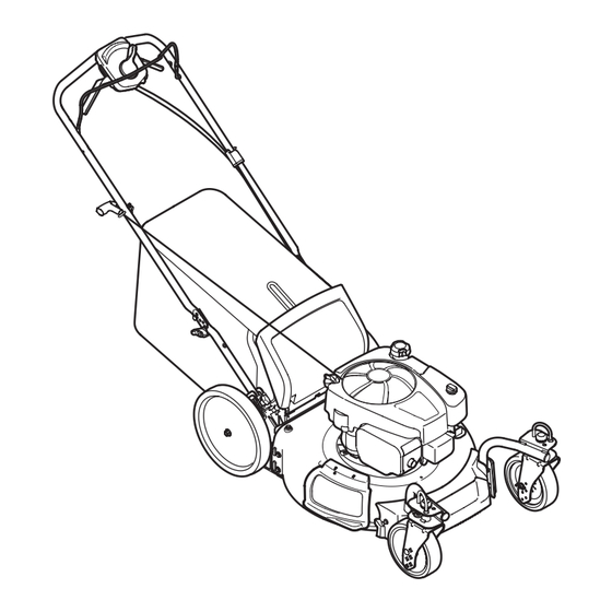
Self Propelled Mower — Model TB 370 XP
WARNING
READ AND FOLLOW ALL SAFETY RULES AND INSTRUCTIONS IN THIS MANUAL
BEFORE ATTEMPTING TO OPERATE THIS MACHINE.
FAILURE TO COMPLY WITH THESE INSTRUCTIONS MAY RESULT IN PERSONAL INJURY.
TROY-BILT LLC, P.O. BOX 361131 CLEVELAND, OHIO 44136-0019
Printed In USA
Form No. 769-10453
(December 10, 2014)
Publicidad

Manuales relacionados para Troy-Bilt TB 370 XP


Resumen de contenidos para Troy-Bilt TB 370 XP
- Página 1 Safe Operation Practices • Set-Up • Operation • Maintenance • Service • Troubleshooting • Warranty ’ peratOr anual Self Propelled Mower — Model TB 370 XP WARNING READ AND FOLLOW ALL SAFETY RULES AND INSTRUCTIONS IN THIS MANUAL BEFORE ATTEMPTING TO OPERATE THIS MACHINE.
- Página 2 Visit us on the web at www.troybilt.com See How-to Maintenance and Parts Installation Videos at www.troybilt.com/tutorials ◊ Call a Customer Support Representative at (800) 828-5500 or (330) 558-7220 ◊ Write to Troy-Bilt LLC • P.O. Box 361131 • Cleveland, OH • 44136-0019...
- Página 3 Important Safe Operation Practices WARNING: This symbol points out important safety instructions which, if not followed, could endanger the personal safety and/or property of yourself and others. Read and follow all instructions in this manual before attempting to operate this machine. Failure to comply with these instructions may result in personal injury.
- Página 4 A missing or damaged discharge cover can cause blade When starting engine, pull cord slowly until resistance contact or thrown object injuries. is felt, then pull rapidly. Rapid retraction of starter cord (kickback) will pull hand and arm toward engine faster than Many injuries occur as a result of the mower being pulled you can let go.
- Página 5 Service Check the blade and engine mounting bolts at frequent intervals for proper tightness. Also, visually inspect blade Safe Handling Of Gasoline: for damage (e.g., bent, cracked, worn) Replace blade with the original equipment manufacture’s (O.E.M.) blade only, To avoid personal injury or property damage use extreme listed in this manual.
- Página 6 Notice Regarding Emissions Spark Arrestor Engines which are certified to comply with California and federal WARNING: This machine is equipped with an EPA emission regulations for SORE (Small Off Road Equipment) internal combustion engine and should not be used are certified to operate on regular unleaded gasoline, and on or near any unimproved forest-covered, brush may include the following emission control systems: Engine covered or grass-covered land unless the engine’s...
- Página 7 Safety Symbols This page depicts and describes safety symbols that may appear on this product. Read, understand, and follow all instructions on the machine before attempting to assemble and operate. Symbol Description READ THE OPERATOR’S MANUAL(S) Read, understand, and follow all instructions in the manual(s) before attempting to assemble and operate DANGER —...
- Página 8 2 — i ection mportant peration racticeS...
- Página 9 Assembly & Set-Up Contents of Carton • One Lawn Mower • One Grass Catcher • One Bottle of Oil • One Lawn Mower Operator’s Manual • One Engine Operator’s Manual • One Side Discharge Chute NOTE: Please be aware that this Operator’s Manual covers both While stabilizing mower so it doesn’t move, pivot the low and high wheel models of this mower.
- Página 10 Remove the T-bolts from the handle brackets as shown in Figure 3-3. Figure 3-5 The rope guide is attached to the right side of the upper handle. Loosen the wing knob which secures the rope Figure 3-3 guide. See Figure 3-6. Follow the steps below to complete handle assembly: Pull upward on the handle approximately 8 inches until holes in lower handle (shown in Figure 3-3 deck...
- Página 11 Slip plastic channel of grass bag over hooks on the On the side of the mower, lift the side mulching plug. See frame. See Figure 3-7. Figure 3-9. Side Mulching Plug Figure 3-7 Figure 3-9 Follow steps below to attach grass catcher: Slide two hooks of side discharge chute under hinge pin on mulching plug assembly.
- Página 12 Drive Control The front wheel cutting height is determined by selecting one of six positions on each caster assembly. To adjust front cutting The adjustment wheel is located in the drive control handle height, refer to Figure 3-10B and proceed as follows: housing and is used to tighten or loosen the drive belt.
- Página 13 Controls and Features Drive Control Speed Control Blade Control Drive Control Recoil Starter Cutting Height Adjustment Lever Side Discharge Deck Wash Blower Side Discharge Chute Figure 4-1 Blade Control Cutting Height Adjustment Lever The blade control is attached to the upper handle of the mower. The cutting height adjustment lever is located above the left Depress and squeeze it against the upper handle to operate the rear wheel.
- Página 14 Operation Starting Engine WARNING: Be sure no one other than the operator is standing near the lawn mower while starting engine or operating mower. Never run engine indoors or in enclosed, poorly ventilated areas. Engine exhaust contains carbon monoxide, an odorless and deadly gas.
- Página 15 Using as Mulcher Side Mulching For mulching grass, remove the grass catcher and allow the rear Plug discharge door to close the rear opening of mower. For effective mulching, do not cut wet grass. If the grass has been allowed to grow in excess of four inches, mulching is not recommended.
- Página 16 Maintenance & Adjustments Maintenance Lubrication Lubricate pivot points on the blade control at least once General Recommendations a season with light oil. This control must operate freely in • Always observe safety rules when performing any both directions. See Figure 6-1. maintenance.
- Página 17 Deck Wash Engine Care Your mower’s deck is equipped with a water port on its surface as A list of key engine maintenance jobs required for good part of its deck wash system. performance by the mower is given below. Follow the accompanying engine manual for a detailed list and instructions.
- Página 18 Service Blade Care Place blade bell support on the blade. Align notches on the blade bell support with small holes in blade. WARNING: When removing the cutting blade for Replace hex bolt and tighten hex bolt to torque: 450 in. lbs. sharpening or replacement, protect your hands with min., 600 in.
- Página 19 Troubleshooting Problem Cause Remedy Engine Fails to start 1. Blade control disengaged. 1. Engage blade control. 2. Spark plug boot disconnected. 2. Connect wire to spark boot. 3. Fuel tank empty or stale fuel. 3. Fill tank with clean, fresh gasoline. 4.
- Página 20 Problem Cause Remedy Occasional skips 1. Spark plug gap too close. 1. Adjust gap. Refer to engine manual. (hesitates) at high speed Idles poorly 1. Spark plug fouled, faulty, or gap too wide. 1. Reset gap or replace spark plug. Refer to engine manual.
- Página 21 Replacement Parts Component Part Number and Description 759-3336 Spark Plug BS-795066 Air Filter Element BS-799585 Carbon Fuel Tank Cap BS-298090S Fuel Filter † 634-04606 Wheel (Front) 934-04666 Wheel (Rear) 731-07131 Discharge Chute 942-0741A Mulching Blade 942-0741-X Xtreme Mulching Blade 964-04141B Grass Bag 954-04282 Belt...
- Página 22 Attachments & Accessories Component Model Number and Description 490-850-0005 Blade Removal Tool — Holds blade in place for faster, safer removal. SPW-134 Spark Plug Wrench — Duel ended wrench to serve multiple uses. Fits ¾” or 13⁄16” hex plug. 490-850-0008 Oil Siphon —...
- Página 23 Component Model Number and Description 22216 STA-BIL® fuel Stabilizer, 32 oz — Treats 80 gallons of fuel. Keeps stored fuel fresh for quick, easy starts. Prevents corrosion from moisture and ethanol-induced attraction. Prevents gum and varnish. 490-290-0012 Mower Cover — Protects your mower against sun, rain and dust damage.
- Página 24 MANUFACTURER’S LIMITED WARRANTY FOR The limited warranty set forth below is given by Troy-Bilt LLC with Log splitter pumps, valves, and cylinders have a separate respect to new merchandise purchased and used in the United one- year warranty. States and/or its territories and possessions, and by MTD Products...
- Página 25 Medidas importantes de seguridad • Configuración • Funcionamiento • Mantenimiento • Servicio • Solución de problemas • Garantía aNual del operador Podadora tipo abonadora autopropulsada — Modelo TB 370 XP ADVERTENCIA LEA Y SIGA TODAS LAS INSTRUCCIONES DE ESTE MANUAL ANTES DE PONER EN FUNCIONAMIENTO ESTA MÁQUINA.
- Página 26 Ver Vídeos demostrativos de instalación de mantenimiento y piezas en www.troybilt.com/Tutorials ◊ Llame a un representante de Asistencia al Cliente al (800) 828-5500 ó (330) 558-7220 ◊ Escríbanos a Troy-Bilt LLC • P.O. Box 361131 • Cleveland, OH • 44136-0019...
- Página 27 Medidas importantes de seguridad ADVERTENCIA: La presencia de este símbolo indica que se trata de instrucciones importantes de seguridad que se deben respetar para evitar poner en peligro su seguridad personal y/o material y la de otras personas. Lea y siga todas las instrucciones de este manual antes de poner en funcionamiento esta máquina.
- Página 28 No ponga las manos o los pies cerca de las piezas rotatorias Nunca opere la cortadora sin las guardas apropiadas, o en la tolva de la cortadora. El contacto con las cuchillas cubierta de descarga, guarda para recorte, manija de puede producir la amputación de manos y pies.
- Página 29 Niños Nunca saque la tapa del gas ni agregue combustible mientras el motor está caliente o en marcha. Deje que el Pueden ocurrir accidentes trágicos si el operador no está atento motor se enfríe por lo menos dos minutos antes de volver a a la presencia de niños.
- Página 30 No modifique el motor Nunca trate de ajustar una rueda o la altura de corte mientras el motor está en marcha. Para evitar lesiones graves o la muerte, no modifique el motor Los componentes de la tolva para recorte, cubierta bajo ninguna circunstancia.
- Página 31 Símbolos De Seguridad Esta página representa y describe la seguridad los símbolos que pueden parecer en este producto. Lea, comprenda, y siga todas instrucciones de la máquina antes de intentar ensamblar y operar. Símbolo Descripción LEA EL MANUAL(S) DEL OPERADOR Lea, comprenda, y siga todas instrucciones en el manual (manuales) antes de operar el producto.
- Página 32 2 — M ección edidaS iMportanteS de Seguridad...
- Página 33 Montaje y Configuración Contenido de la caja • Una Podadora • Uno Colector de Césped • Uno Botella del Aceite • Uno Manual de Operador • Uno Manual de Operador de Motor • Uno Canal de Descarga Lateral NOTA: Tenga en cuenta que este manual del operador abarca tanto los modelos de rueda alta y baja de este cortacésped.
- Página 34 Siga los siguientes pasos para completar conjunto del La guía de la cuerda está unida al costado derecho de la mango: manija superior. Afloje la tuerca de mariposa que sujeta la guía de la cuerda, Figura 3-6. Tire hacia arriba aproximadamente 8 pulgadas en el asa hasta agujeros en la manija (que se muestra en Figura 3-3 corte de la cubierta) se alinean con los agujeros en el mango soporte.
- Página 35 En el costado de la podadora, levante el adaptador para abono. Vea Figura 3-9. Clavija para abono lateral Figura 3-7 Para acoplar el colector de césped. Figura 3-9 Levante la puerta de descarga posterior. Deslice los dos ganchos del canal de descarga lateral Lugar de colección de césped en las ranuras en el debajo del pasador de bisagra sobre el montaje del mango entre corchetes como se muestra en Figura...
- Página 36 Control de transmisión Libere la palanca hacia la plataforma de la cortadora. La altura de corte de la rueda frontal se determina seleccionando La rueda de ajuste está ubicada en el alojamiento de la manija una de las seis posiciones en el montaje de cada ruedita. Para de control de transmisión y se utiliza para ajustar o aflojar la ajustar la altura de corte frontal, consulte Figura 3-10B y realice lo correa de transmisión.
- Página 37 Controles Y Características Control de la Control de la transmisión Velocidad Control de cuchilla Control de la transmisión Arrancador Palanca de de retroceso ajuste de altura de corte Lavado de la Soplador de Plataforma Descarga Lateral Canal de Descarga Lateral Figura 4-1 Control de Cuchilla motor corre.
- Página 38 Funcionamiento Encendido del Motor ADVERTENCIA: Asegúrese que ninguna persona aparte del operador permanezca cerca de la podadora mientras arranca el motor u opera la misma. Nunca encienda un motor en espacios cerrados o en una zona con poca ventilación. El escape del motor contiene monóxido de carbono, un gas inodoro y letal.
- Página 39 NOTA: La máquina está equipada con un avanzado sistema de tracción interior de la facilidad de uso y cambios suaves. Clavija para Al girar o tirar de la unidad hacia atrás, usted puede notar abono lateral más alta que la resistencia normal en las ruedas traseras bajo ciertas condiciones.
- Página 40 Mantenimiento Y Ajustes Mantenimiento Lubricación Lubrique con aceite ligero los puntos de pivote del control Recomendaciones Generales de la cuchilla al menos una vez cada estación. Este control • Respete siempre las reglas de seguridad cuando realice debe funcionar libremente en ambas direcciones, Figura 6-1.
- Página 41 Lavado de la Plataforma Cuidados para el motor La plataforma de su podadora está equipada con un puerto de A continuación se presenta una lista de tareas de mantenimiento agua sobre su superficie como parte del sistema de lavado de la necesarias para el buen funcionamiento de la cortadora de plataforma.
- Página 42 Cuchilla Cuidado de la correa NOTE: Varios componentes deben ser quitados a fin de cambiar el cinturón del cortacésped. Ver a un Distribuidor de Servicio de Troy-Bilt autorizado para hacer sustituir su cinturón. Soporte de Campana de Perno la Cuchilla...
- Página 43 Almacenamiento Fuera de Temporada Se deben seguir estos pasos para la preparación de la podadora para su almacenamiento. • Limpie y lubrique la podadora como se describe en Las instrucciones de lubricación. • Asegure tolva de descarga lateral para manejar como se muestra en Figure 7-2.
- Página 44 Solución de problemas Problema Causa Remedio El motor no arranca 1. El control de lámina se retiró. 1. Contratar el control de lámina. 2. Alambre de bujía desconectado. 2. Unir el alambre a la bujía. 3. Depósito de combustible combustible vacío 3.
- Página 45 Problema Causa Remedio Saltos ocasionales 1. La distancia disruptiva de la bujía es muy 1. Ajuste la distancia disruptiva a 0,76 mm (0,03 (pausas) a pequeña. pulg). alta velocidad Funciona mal en 1. Bujía atorada, averiada o exceso de distancia 1.
- Página 48 Las disposiciones de esta garantía cubren el recurso de reparación para cuchillas, dientes, bolsas para pasto, ruedas, ruedas para la única y exclusiva que surge de la venta. Troy-Bilt no se hará plataforma de la podadora tractor, asientos, zapatas antideslizantes, responsable de ninguna pérdida o daño incidental o resultante,...