Yamaha C-5000 Manual De Instrucciones
Ocultar thumbs
Ver también para C-5000:
- Manual de instrucciones (324 páginas) ,
- Folleto de seguridad (37 páginas)
Tabla de contenido
Publicidad
Idiomas disponibles
Idiomas disponibles
Enlaces rápidos
Publicidad
Capítulos
Tabla de contenido
Solución de problemas

Manuales relacionados para Yamaha C-5000


Resumen de contenidos para Yamaha C-5000
- Página 1 Pre-Amplifier Owner´s Manual Manual de instrucciones...
-
Página 2: Features
¡ To use the product properly and safely, we suggest that you read this manual and Safety Brochure (separate booklet) thoroughly. Keep the manual in a safe, accessible place for future reference. You can download a PDF version of this manual from the following Yamaha website. https://download.yamaha.com/ Features ¡... -
Página 3: Tabla De Contenido
Operating the unit from another room . . 25 Remote connection between Yamaha components . . . . . . . . . . . . . . . . . . . 25... -
Página 4: Supplied Accessories
. • If you wipe the surface area in the vicinity of the Yamaha logo with force, the logo might peel off or fiber from the cloth might stick to the surface . -
Página 5: Part Names And Functions
Part Names and Functions This section lists the names and describes the function of various parts on the front and rear panels, and the remote control. -
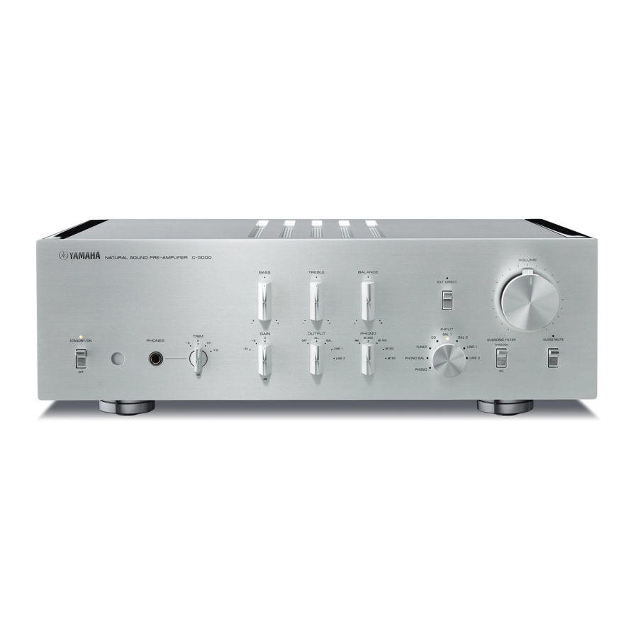
Página 6: Front Panel
Front panel STANDBY/ON/OFF (Power) Note switch/ indicator After you turn on the unit, it will take a few seconds before the unit can reproduce sound . Turns the power to the unit on (standby) or off. STANDBY/ON: Switches between standby and on using NOTICE the A AMP key on the remote control. - Página 7 TRIM selector OUTPUT selector Switches the headphone amp gain. The unit will adjust LINE1 LINE2 the volume level when headphones are plugged in to avoid sudden changes in volume by modifying the level — Output Output — — balance between the audio output from the PHONES jack jacks and from the speakers.
-
Página 8: Bass Control
Front panel BASS control EXT. DIRECT switch/indicator Adjusts the low-frequency response in the range from If you press the EXT. DIRECT switch once, the EXT. −10 dB to +10 dB (in 0.5 dB steps). The center position DIRECT indicator will light up, and the audio source produces a flat response. -
Página 9: Volume Control
µ ¸ ¹ INPUT selector/indicator AUDIO MUTE switch/indicator Enables you to select the input source to play back. Press this switch to reduce the current volume level by Options are: PHONO, PHONO BAL, TUNER, CD, BAL 1, approximately 20 dB. The indicator will light up. Press BAL 2, LINE 1, and LINE 2. -
Página 10: Rear Panel
Rear panel Note CAUTION For information regarding the connection procedure, refer to “Connections” (page 19) . Handle the shorting plugs carefully . Do not allow children to play with the shorting plug; otherwise they might swallow it . PHONO jacks NOTICE RCA and XLR-type jacks. - Página 11 BAL 1/BAL 2 jacks PHASE selector These are two sets of XLR-type balanced input jacks. If Specifies the HOT pin position for the XLR-type the INPUT selector is set to BAL 1 or BAL 2, signals at balanced input jacks (BAL 1 and BAL 2 jacks). the corresponding XLR jacks will be the input source.
- Página 12 Rear panel µ CD jacks Note • Connect the LINE 2 IN jacks and LINE 2 OUT (recording) These are RCA input jacks. If the INPUT selector is set jacks to the same component . to CD, signals at these jacks will be the input source. • The LINE 2 OUT (recording) jacks will not output any Connect your CD player here.
- Página 13 µ ¸ ¹ REMOTE IN/REMOTE OUT jacks Note The volume level is fixed . Operating the VOLUME control or These are monaural mini jacks. Connect external GAIN selector on this unit will not change the volume level components that support the remote function here. of the signal from the EXT .
-
Página 14: Balanced And Unbalanced Connections
. The pin polarity of these jacks is standard and Lever fixed . • Pin #2 is Hot on Yamaha players . When connecting a cable to an input jack, be sure to align the pins on the connector with the holes in the jack, and then insert the connector into the jack until you hear a click. - Página 15 Unbalanced connection If you are connecting an audio component that features only standard RCA jacks, use the RCA jacks on this unit for unbalanced connections. For unbalanced connections, unbalanced cables with RCA connectors should be used. These jacks and connectors do not feature a male or female design nor polarity differences.
-
Página 16: Remote Control
Tuner control keys Enable you to control the functions of the connected MUTE Yamaha tuner. Use the BAND key to switch the reception band, and the PRESET er keys to select a preset station. For more information, refer to the owner’s manual for your tuner. - Página 17 A CD key VOLUME +/− keys Turns on the power to a connected Yamaha CD player, or Adjust the volume level. switches it to standby mode. Note The VOLUME +/− keys on the remote control will not affect OPEN/CLOSE key the volume level if EXT .
-
Página 18: Installing Batteries In The Remote Control
Installing batteries in the remote CAUTION control • Do not use a new and old batteries at the same time . Otherwise, fire, burns, or irritation due to leaking battery liquid might be caused . Remove the battery compartment cover • Do not use two different types of batteries at the same time . -
Página 19: Connections
Connections This section explains how to connect the unit to an audio source, such as a tuner or CD player, and a power amplifier. CAUTION Turn off the power to all components before making any connections . NOTICE • Do not use balanced and unbalanced connections between two components simultaneously . Doing so would create a ground loop that could generate static and noise . -
Página 20: Connecting An External Component
Connecting an external component Turntable Turntable CD player CD player BD player Network audio player Tuner Hard disk recorder,... - Página 21 Other preamplifier Power amplifier Active subwoofer AV amplifier, etc Power amplifier NOTICE Do not use balanced and unbalanced connections between two components simultaneously . Doing so would create a ground loop that could generate static and noise .
-
Página 22: Connecting A Turntable
Connecting a turntable Connecting a recording component Connect your turntable to the PHONO jacks on this unit. The unit provides XLR-type balanced jacks and RCA- You can connect a recording device, such as a hard disk type unbalanced input jacks. recorder to the unit, and record audio input from the unit. -
Página 23: Connecting Another Preamplifier
Connecting another Connecting a power amplifier preamplifier and an active subwoofer If you connect the output of another preamplifier to the You can connect a power amplifier and an active EXT. IN jacks on this unit and press the EXT. DIRECT subwoofer to the BAL, LINE 1, or LINE 2 output jacks switch, the source signal will pass through the unit and on this unit. -
Página 24: Trigger Connections
You can control the unit’s power on-and-off operation connected component, such as a Yamaha CD player or in sync with a connected component, such as a Yamaha power amplifier, in sync with this unit. AV receiver. Use an optional system cable to connect the unit’s TRIGGER IN jack to the connected component’s... -
Página 25: Remote Connections
Yamaha components If you connect an infrared receiver and transmitter to If you have another Yamaha component that supports the unit’s REMOTE IN/OUT jacks, you will be able to remote connections, as this unit does, an infrared operate the unit and/or external component from another transmitter is not necessary. -
Página 26: Connecting The Power Cord
Otherwise, continued use of the unit might lead to electric shock, fire, or malfunction . Contact your nearest Yamaha dealer or service center for check-up or repair . • Do not touch the power cord or plug during lightning storms . Otherwise, an electric shock might be caused . -
Página 27: Operations
Operations This section explains basic operating procedures. You can follow these procedures to take advantage of the unit’s functions. These procedures are intended only as examples. -
Página 28: Turning The Power On
Turning the power on Selecting the input and output CAUTION Select a pair of output jacks using the OUTPUT selector. Be sure to lower the volume level to minimum before turning the power on . Turn the power on by setting the STANDBY/ON/OFF (Power) switch on the front panel to STANDBY/ON. -
Página 29: Selecting The Input From The Ext.in Jacks
Adjusting the turntable input Selecting the input from the setting EXT.IN jacks PHONO selector Set the PHONO selector according to the turntable cartridge. Options for turntable cartridge Press the EXT. DIRECT switch. The EXT. DIRECT MM-type cartridge indicator will light up. The INPUT selector setting will be disabled, and the audio source input from the EXT. -
Página 30: Subsonic Filter
Adjusting the volume level Subsonic filter Set the gain using the GAIN selector so that you can Turn on the SUBSONIC FILTER switch to apply the subsonic filter, as needed. make fine volume adjustments. A resonating turntable tone arm or a warped vinyl record could cause a very low frequency rumble (subsonic noise) that might apply load and damage to the speakers. -
Página 31: Lowering The Volume Level Momentarily
Adjusting the tone Adjust the volume level balance between the left and Lowering the volume level right speakers using the BALANCE control. momentarily Press the AUDIO MUTE switch to reduce the current volume level by approximately 20 dB. Press the switch again to restore the previous volume level. -
Página 32: Connecting Headphones
Connecting headphones If headphones are connected to the PHONES jack, no signal will be output at the output jacks (BAL, LINE 1, and LINE 2 output jacks) on the rear panel. Use the TRIM selector to switch the headphone amp gain so you can adjust the level balance between the audio output from the PHONES jack and the speakers to avoid sudden changes in volume. -
Página 33: Reference Materials
Reference Materials... -
Página 34: General Specifications
General specifications Rated output voltage/output impedance Total harmonic distortion plus noise (Input 200 mV, 20 Hz to 20 kHz, THD 0 01%) (JEITA, input 0 5 V, 20 Hz to 20 kHz) BAL (BYPASS) ....2 Vrms/150Ω BAL 1/BAL 2/TUNER/CD/LINE 1/LINE 2 IN →... - Página 35 ........19.1 kg * The contents of this manual apply to the latest specifications as of the publishing date. To obtain the latest manual, access the Yamaha website then download the manual file.
-
Página 36: Block Diagram
Block diagram SUBSONIC FILTER TONE CONTROL... -
Página 37: Audio Characteristics
Audio characteristics Frequency response (tone control) +10dB +8dB +6dB +4dB +2dB ±0dB –2dB –2 –4dB –4 –6dB –6 –8dB –8 –10dB –10 –12 –14 200 300 100k Frequency (Hz) Total harmonic distortion (PHONO) 20 Hz 1 kHz 20 kHz 0.05 0.02 0.01 0.005... -
Página 38: Frequency Response (Subsonic Filter)
Frequency response (subsonic filter) THROUGH –5 –10 –15 –20 –25 200 300 20k 30k 100k Frequency (Hz) Volume curve GAIN selector: –6 dB –20 GAIN selector: 0 dB –40 GAIN selector: –12 dB –60 –80 –100 –110 0.00 50.00 100.00 150.00 200.00 250.00... -
Página 39: Troubleshooting
Refer to the table below if this unit does not function properly. If the instructions below do not help, or if the problem you are experiencing is not listed below, turn off the unit, disconnect the power cord, and contact the nearest authorized Yamaha dealer or service center. Problem... - Página 40 Problem Cause Remedy page Connect the cables properly. If the Incorrect input or output cable problem persists, the cables might be connections. defective. The turntable is not grounded to Connect the turntable to the GND A “humming” noise is the GND terminal. terminal of this unit.
-
Página 41: Index
Index AC IN jack ....... 26 OUTPUT selector ......28 Adjusting the turntable input . -
Página 42: Funciones
¡ Para utilizar el producto de forma adecuada y segura, le sugerimos que lea detenidamente este manual y el Folleto de seguridad (folleto independiente). Conserve el manual en un lugar seguro y de fácil acceso como referencia futura. Puede descargar una versión en PDF de este manual desde el siguiente sitio web de Yamaha. https://download.yamaha.com/ Funciones ¡... - Página 43 Control de la operación de encendido y apagado de la unidad de manera sincronizada con un componente conectado, como un receptor AV Conexiones remotas Control de la unidad desde otra habitación Conexión remota entre componentes Yamaha Conexión del cable de alimentación...
-
Página 44: Accesorios Suministrados
(diluido en agua), escúrralo bien y limpie la suciedad • Si limpia la zona de la superficie cercana al logotipo de Yamaha con fuerza, es posible que el logotipo se despegue o que se adhieran fibras del paño a la superficie Paneles laterales con acabado de espejo Se recomienda utilizar un paño de limpieza como los destinados a pianos. -
Página 45: Nombres Y Funciones De Las Piezas
Nombres y funciones de las piezas En esta sección se enumeran los nombres y se describen las funciones de las distintas piezas de los paneles delantero y trasero, así como del mando a distancia. -
Página 46: Panel Delantero
Panel delantero Interruptor/indicador STANDBY/ON/ Nota OFF (alimentación) Tras encender la unidad, tendrá que esperar unos segundos antes de que pueda reproducir sonido Activa (espera) o desactiva la alimentación de la unidad. STANDBY/ON: cambia entre el modo de espera y el AVISO activado usando la tecla A AMP del mando a distancia. - Página 47 Selector TRIM Selector OUTPUT LINE1 LINE2 Cambia la ganancia del amplificador de auriculares. La unidad ajustará el nivel de volumen cuando los Jacks — Salida Salida — — auriculares estén conectados para evitar cambios repentinos de volumen modificando el balance de nivel Jacks entre la salida de audio procedente del jack PHONES y —...
-
Página 48: Control Balance
Panel delantero Control BASS Interruptor/indicador EXT. DIRECT Ajusta la respuesta de frecuencia baja en la gama de Si pulsa el interruptor EXT. DIRECT una vez, el −10 dB a +10 dB (en pasos de 0,5 dB). La posición indicador EXT. DIRECT se iluminará, y la entrada de central produce una respuesta plana. -
Página 49: Selector/Indicador Input
µ ¸ ¹ Selector/indicador INPUT Interruptor/indicador AUDIO MUTE Permite seleccionar la fuente de entrada que se va a Pulse este interruptor para reducir el nivel de volumen reproducir. Las opciones son: PHONO, PHONO BAL, actual 20 dB aproximadamente. El indicador se iluminará. TUNER, CD, BAL 1, BAL 2, LINE 1 y LINE 2. -
Página 50: Panel Trasero
Panel trasero Nota ATENCIÓN Para obtener información acerca del procedimiento de conexión, consulte “Conexiones” (página 59) Manipule las clavijas de cortocircuito con cuidado No permita que los niños jueguen con la clavija de cortocircuito; de lo contrario, podrían ingerirla Jacks PHONO AVISO Jacks de tipo RCA y XLR. - Página 51 Jacks BAL 1/BAL 2 Selector PHASE Se trata de dos juegos de jacks de entrada balanceada Especifica la posición del contacto con corriente para los de tipo XLR. Si el selector INPUT se ha establecido jacks de entrada balanceada de tipo XLR (jacks BAL 1 y en BAL 1 o BAL 2, las señales en los jacks XLR BAL 2).
- Página 52 Panel trasero µ Jacks CD Nota • Conecte los jacks LINE 2 IN y los jacks LINE 2 OUT Se trata de jacks de entrada RCA. Si el selector INPUT se (grabación) al mismo componente ha establecido en CD, las señales en estos jacks serán la • Los jacks LINE 2 OUT (grabación) no emitirán señales fuente de entrada.
- Página 53 µ ¸ ¹ Jacks REMOTE IN/REMOTE OUT Nota El nivel de volumen es fijo Al manipular el control VOLUME Se trata de mini jacks monaurales. Conecte componentes o el selector GAIN en esta unidad no cambiará el nivel externos compatibles con la función remota aquí. Para de volumen de la señal procedente de los jacks EXT IN obtener más información, consulte “Conexiones remotas”...
-
Página 54: Conexiones Balanceadas Y No Balanceadas
Palanca estándar y fija • El contacto n º 2 tiene corriente en los reproductores Yamaha Al conectar un cable a un jack de entrada, asegúrese de alinear los contactos del conector con los orificios del jack y, a continuación, inserte el conector en el jack hasta que oiga un chasquido. -
Página 55: Conexión No Balanceada
Conexión no balanceada Si va a conectar un componente de audio que solo incluye jacks RCA estándar, utilice los jacks RCA de esta unidad para conexiones no balanceadas. Para conexiones no balanceadas, se deben utilizar cables no balanceados con conectores RCA. Estos jacks y conectores no presentan un diseño de tipo macho o hembra ni diferencias de polaridad. -
Página 56: Mando A Distancia
MUTE Teclas de control del sintonizador Le permiten controlar las funciones del sintonizador Yamaha conectado. Utilice la tecla BAND para cambiar la banda de recepción y las teclas PRESET er para seleccionar una emisora presintonizada. Para obtener más información, consulte el manual del propietario del sintonizador. - Página 57 Es posible que algunos modelos de reproductor de CD Reduce el nivel de volumen actual en aproximadamente Yamaha no sean compatibles con las funciones de la tecla 20 dB. Pulse la tecla de nuevo para reponer la salida de A CD o de las teclas OPEN/CLOSE audio al nivel de volumen anterior.
-
Página 58: Instalación De Las Pilas En El Mando A Distancia
Instalación de las pilas en el ATENCIÓN mando a distancia • No utilice nuevas y antiguas al mismo tiempo De lo contrario, podrían producirse incendios, quemaduras o irritaciones debido a la fuga de líquido de las pilas Retire la tapa del compartimento de las • No utilice dos tipos distintos de pilas al mismo pilas tiempo Por ejemplo, si utiliza una pila alcalina y una... -
Página 59: Conexiones
Conexiones En esta sección se describe cómo conectar la unidad a una fuente de audio, como un sintonizador o un reproductor de CD, y a un amplificador de potencia. ATENCIÓN Desactive la alimentación de todos los componentes antes de realizar conexiones AVISO • No utilice conexiones balanceadas y no balanceadas entre dos componentes simultáneamente Si lo hace se creará... -
Página 60: Conexión De Un Componente Externo
Conexión de un componente externo Reproductor de CD Giradiscos Giradiscos Reproductor de CD Reproductor de BD Reproductor de audio de red Sintonizador Grabador de disco duro, etc... - Página 61 Amplificador de Altavoz de subgraves Otro preamplificador potencia activo Amplificador AV, etc Amplificador de potencia AVISO No utilice conexiones balanceadas y no balanceadas entre dos componentes simultáneamente Si lo hace se creará un bucle a tierra que podría generar estática y ruido...
-
Página 62: Conexión De Un Giradiscos
Conexión de un giradiscos Conexión de un componente de grabación Conecte el giradiscos a los jack PHONO de esta unidad. La unidad proporciona jacks balanceados de tipo XLR y Puede conectar un dispositivo de grabación, como un jacks de entrada no balanceada de tipo RCA. grabador de disco duro, a la unidad y grabar la entrada de audio procedente de la unidad. -
Página 63: Conexión De Otro Preamplificador
Conexión de otro Conexión de un amplificador preamplificador de potencia y un altavoz de subgraves activo Si conecta la salida de otro preamplificador a los jacks EXT. IN de esa unidad y pulsa el interruptor EXT. Puede conectar un amplificador de potencia y un altavoz DIRECT, la señal de fuente atravesará... -
Página 64: Conexiones De Activación
Puede controlar la operación de encendido y apagado conectado, como un receptor AV Yamaha. Utilice un cable de un componente conectado, como un reproductor de del sistema opcional para conectar el jack TRIGGER IN... -
Página 65: Conexiones Remotas
Yamaha Si conecta un receptor y un transmisor de señales Si dispone de otro componente Yamaha compatible con infrarrojas a los jacks REMOTE IN/OUT de la unidad, conexiones remotas, como es el caso de esta unidad, podrá controlar la unidad o un componente externo desde no es necesario un transmisor de infrarrojos. -
Página 66: Conexión Del Cable De Alimentación
Póngase en contacto con su centro de servicio o distribuidor Yamaha más cercano para una revisión o una reparación • No toque el cable o enchufe de alimentación durante tormentas eléctricas De lo contrario, se puede provocar... -
Página 67: Operaciones
Operaciones En esta sección se describen los procedimientos básicos de funcionamiento. Puede seguir estos procedimientos para aprovechar las funciones de la unidad. Estos procedimientos se proporcionan simplemente como ejemplos. -
Página 68: Encendido De La Unidad
Encendido de la Selección de la unidad entrada y la salida Seleccione una pareja de jacks de salida con el selector OUTPUT. ATENCIÓN Asegúrese de bajar el nivel de volumen al mínimo antes de activar la alimentación Active la alimentación estableciendo el interruptor STANDBY/ON/OFF (alimentación) en el panel delantero en STANDBY/ON. -
Página 69: Selección De La Entrada Desde Los Jacks Ext In
Selección del ajuste de entrada del Selección de la entrada desde giradiscos los jacks EXT.IN Selector PHONO Ajuste el selector PHONO en función del cartucho del giradiscos. Opciones para cartucho del giradiscos Pulse el interruptor EXT. DIRECT. El indicador EXT. Cartucho de tipo MM DIRECT se iluminará. -
Página 70: Filtro Subsónico
Ajuste del nivel de volumen Filtro subsónico Ajuste la ganancia usando el selector GAIN para poder Active el interruptor SUBSONIC FILTER para aplicar el filtro subsónico, en caso necesario. realizar ajustes precisos del volumen. Un brazo fonocaptor de giradiscos resonante o un disco de vinilo combado pueden provocar una reverberación de frecuencia muy baja (ruido subsónico) que podría aplicar carga y daños a los altavoces. -
Página 71: Bajada Momentánea Del Nivel De Volumen
Ajuste del tono Ajuste el balance de nivel de volumen entre los altavoces Bajada momentánea del nivel izquierdo y derecho usando el control BALANCE. de volumen Pulse el interruptor AUDIO MUTE para reducir el nivel de volumen actual 20 dB aproximadamente. Pulse el interruptor de nuevo para reponer el nivel de volumen anterior. -
Página 72: Conexión De Auriculares
Conexión de auriculares Si hay auriculares conectados al jack PHONES, no se emitirá ninguna señal por los jacks de salida (jacks de salida BAL, LINE 1 y LINE 2) en el panel trasero. Utilice el selector TRIM para cambiar la ganancia del amplificador de auriculares de modo que pueda ajustar el balance de nivel entre la salida de audio del jack PHONES y los altavoces para evitar cambios repentinos... -
Página 73: Materiales De Referencia
Materiales de referencia... -
Página 74: Especificaciones Generales
Especificaciones generales Tensión de salida nominal/impedancia de salida Distorsión armónica total más ruido (entrada a 200 mV, de 20 Hz a 20 kHz, THD 0,01%) (JEITA, entrada 0,5 V, de 20 Hz a 20 kHz) BAL (BYPASS) ....2 Vrms/150 Ω BAL 1/BAL 2/TUNER/CD/LINE 1/LINE 2 IN →... -
Página 75: Alimentación
........19,1 kg * El contenido de este manual se aplica a las últimas especificaciones según la fecha de publicación. Para obtener el último manual, acceda al sitio web de Yamaha y descargue el archivo del manual. -
Página 76: Diagrama En Bloques
Diagrama en bloques SUBSONIC FILTER TONE CONTROL... -
Página 77: Características De Audio
Características de audio Respuesta de frecuencia (control de tono) +10dB +8dB +6dB +4dB +2dB ±0dB –2dB –2 –4dB –4 –6dB –6 –8dB –8 –10dB –10 –12 –14 200 300 100k Frequency (Hz) Distorsión armónica total (PHONO) 20 Hz 1 kHz 20 kHz 0.05 0.02... -
Página 78: Filtro Subsónico
Filtro subsónico THROUGH –5 –10 –15 –20 –25 200 300 20k 30k 100k Frequency (Hz) · Curva de volumen GAIN selector: –6 dB –20 GAIN selector: 0 dB –40 GAIN selector: –12 dB –60 –80 –100 –110 0.00 50.00 100.00 150.00 200.00 250.00... -
Página 79: Resolución De Problemas
Yamaha autorizado más cercano. Consulte... - Página 80 Consulte Problema Causa Solución la página Conecte los cables correctamente. Si Conexiones incorrectas de los el problema persiste, es posible que cables de entrada o salida. los cables estén defectuosos. El giradiscos no está conectado Conecte el giradiscos al terminal GND Se oye un ruido de a tierra en el terminal GND.
-
Página 81: Índice
Índice Activación, conexión ..... . . 64 LINE 1, jack ......53 Ajuste de la entrada del giradiscos . - Página 84 Yamaha Global Site https://www.yamaha.com/ Yamaha Downloads https://download.yamaha.com/ Manual Development Group © 2018 Yamaha Corporation Published 10/2018 IPEM-A0 VAQ1820 10-1 Nakazawa-cho, Naka-ku, Hamamatsu, 430-8650 Japan...