Tabla de contenido
Publicidad
Idiomas disponibles
Idiomas disponibles
Enlaces rápidos
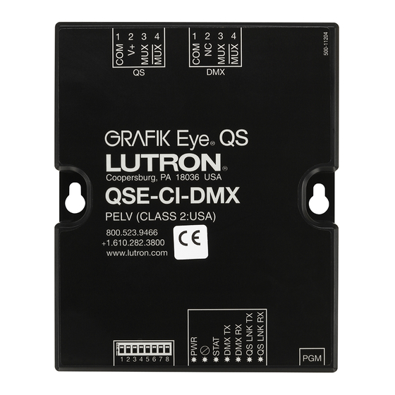
QS DMX Control Interface
Installation and Operation Instructions
Occupant Copy
040439 Rev. A
02/28/19
The QSE-CI-DMX control interface allows zones on a GRAFIK
Eye QS control unit or Quantum processor to control DMX512-
controlled devices. Any zone on the GRAFIK Eye QS or Quantum
processor can be mapped to either a single DMX512 channel or
to three separate DMX512 channels for RGB/CMY color-control
applications.
Key Features
• Map any zone on a GRAFIK Eye QS control unit or Quantum
processor to any single DMX512 channel
• Map any zone on a GRAFIK Eye QS control unit or Quantum
processor simultaneously to three DMX512 channels for RGB/
CMY color-control
• Integral RGB/CMY color lookup table that maps GRAFIK Eye QS
or Quantum zone intensities to RGB/CMY values
• For GRAFIK Eye QS Systems: RGB/CMY table can be
customized by using the Lutron QS Color Configuration Tool (PC
application available on the CD packaged with the QSE-CI-DMX,
and on www.lutron.com/qs)
• For Quantum Systems: RGB/CMY table can be customized by
using the Lutron Q-Design software
QS System
Lutron QS System components communicate over the highly
flexible QS link. There are a few rules to keep in mind when
designing and installing QS system components:
• Up to 100 devices on one QS link
• Up to 100 zones on one QS link
• Up to 2000 ft (610 m) QS link wiring length
• QSE-CI-DMX counts as one (1) device on the QS link
• Up to 32 DMX channel outputs
Dimensions
1.0 in
LEDs and
(26.9 mm)
addressing
switches
on this side
2.47 in
(62.74 mm)
2.47 in
(62.74 mm)
3.75
Terminal blocks
on this side
Please Read
4.26 in
(108.2 mm)
Mounting Holes
2.50
4.26
5.26
1.06
3.75 in
(95.3 mm)
QSE-CI-DMX
SELV / PELV / NECR Class 2 Device 24–36 V- 60 mA
Requirements
The QSE-CI-DMX consumes 2 PDUs (Power Draw Units) on the
QS link, and requires the following:
• To power the system, either:
– At least one GRAFIK Eye QS control unit wired to the
QSE-CI-DMX through the QS communication link
Note: A QS Link Power Supply, such as the QSPS-P1-1-35V,
may be required if the total power draw units consumed
by QS accessories is greater than the supply capacity
of the GRAFIK Eye QS (see Lutron P/N 369405, "Power
Draw Units on the QS Link," for more information on
Power Draw Units)
or:
– A Quantum processor
Note: A Quantum Light Management Hub may be required
if the total power draw units consumed by QS accessories is
greater than the supply capacity of the Quantum processor
(see Lutron PN 369405, "Power Draw Units on the QS Link,"
for more information on Power Draw Units)
• DMX512 link terminators at both ends of the DMX512 link
(available from Lutron, part number LT-1)
• QS Communication Link Wire (SELV / PELV / NECR Class 2):
see table on page 2
Mounting Options
Choose a mounting method below. Mount the control interface
in an accessible location.
A. Direct Wall Mounting. Mount the control interface directly
on a wall, as shown in the Mounting Diagram, using screws
(included). When mounting, provide sufficient space for
connecting cables.
B. Rack Mounting. Place the interface in the LUT-19AV-1U AV
rack using #6 or #8 (M3 or M4) screws (not included). The
LUT-19AV-1U will hold up to four units.
C. Enclosed Wall Mounting. If conduit is desired for wiring, the
LUT-5x10-ENC can be used to mount one unit.
A.
Control
Interface
5.26 in
(133.6 mm)
Direct Wall
Mounting
B.
Wall
LUT-19AV-1U
AV Rack Mount
(Unit not included)
C.
LUT-5x10-ENC
Wall Mount Enclosure
(Unit not included)
1
Publicidad
Tabla de contenido

Manuales relacionados para Lutron QSE-CI-DMX


Resumen de contenidos para Lutron QSE-CI-DMX
- Página 1 • Up to 2000 ft (610 m) QS link wiring length on a wall, as shown in the Mounting Diagram, using screws • QSE-CI-DMX counts as one (1) device on the QS link (included). When mounting, provide sufficient space for •...
- Página 2 ) wires. – A GRAFIK Eye QS control unit • The QSE-CI-DMX consumes 2 power draw units on the QS link. – A QS link power supply (QSPS model numbers) See Lutron PN 369405, "Power Draw Units on the QS Link," for –...
- Página 3 DMX-512 Link Wiring Connect the DMX link terminals on the QSE-CI-DMX interface to input terminals on DMX512-controlled equipment. • Each terminal on the QSE-CI-DMX accepts two 18 AWG (1.0 mm ) or one 12 AWG (4.0 mm ) wires. • DMX Link must be 1000 ft (305 m) or less.
-
Página 4: Display Type
This 6. Exit programming mode: Press and hold the programming programming section applies only to systems controlled using a button on the QSE-CI-DMX for 3 seconds. The "Status" LED will Zone 4 GRAFIK Eye QS control unit. resume slow blinking (once per second). - Página 5 To enable/disable Master Raise/Lower from affecting High end Zone 4 Component 1 channel 1. Enter programming mode on the QSE-CI-DMX: Press and hold RGB/CMY zones (disabled by default) Choose Channel on Set zones the programming button for 3 seconds. The "Status" LED will 1.
- Página 6 Mexico: +1.888.235.2910 of its components. Central/South America: +1.610.282.6701 3. Equipment and parts external to the unit, including those sold or supplied by Lutron (which may be covered by a separate warranty). European Headquarters 4. The cost of repairing or replacing other property that is damaged when the unit does not work properly, even if the damage was caused by the unit.
-
Página 7: Interfaz De Control Dmx Qs
• Hasta 610 m (2 000 pi) de longitud de cableado de QS Link directamente en la pared, como se muestra en el diagrama • El QSE-CI-DMX cuenta como un (1) dispositivo en el QS Link de montaje, utilizando tornillos (incluidos). Durante el montaje, •... -
Página 8: Cableado De Control Del Qs Link
(18 AWG). – Un equipo de control GRAFIK Eye QS • El QSE-CI-DMX consume dos unidades de energía en el QS – Una fuente de alimentación QS Link (números de modelo de Link. Para obtener más información sobre las unidades de QSPS) consumo de energía consulte Lutron NP 369405, "Unidades de... -
Página 9: Cableado Del Dmx-512 Link
Cableado del DMX-512 Link Conecte los terminales DMX Link de la interfaz QSE-CI-DMX a los terminales de entrada de los equipos controlados por el DMX512. • Cada terminal del QSE-CI-DMX acepta dos cables 1,0 mm (18 AWG) o un cable 4,0 mm (12 AWG). -
Página 10: Programación
6. Salga del modo de programación.: Presione y mantenga Zona 4 sección de programación sólo rige para los sistemas controlados presionado el botón de programación del QSE-CI-DMX durante utilizando un equipo de control GRAFIK Eye QS. tres segundos. El LED "Estado" volverá a destellar lentamente (una vez por segundo). - Página 11 QSE-CI-DMX durante RGB/CMY DMX Zona L para no asignar El QSE-CI-DMX se suministra con una tabla estándar de colores tres segundos. El LED amarillo de estado destellará una vez por ya cargados. Los usuarios pueden modificar la tabla para lograr segundo.
- Página 12 7200 Suter Road Si el equipo es puesto en servicio por Lutron o por un tercero aprobado por Lutron como parte de un sistema de control Coopersburg, PA 18036-1299 de iluminación contratado a Lutron, el plazo de esta garantía se extenderá, y todos los créditos contra el costo de las piezas TEL: +1.610.282.3800...
-
Página 13: Interface De Commande Dmx Qs
• Un bus QS peut avoir une longueur maximale de 610 m (2 000 pi) Possibilités de montage • Un QSE-CI-DMX compte comme un (1) équipement sur le bus QS Choisissez une des méthodes de montage ci-dessous; Installez • Jusqu'à 32 sorties canal DMX l'interface de commande dans un endroit accessible. - Página 14 (18 AWG). – une unité de commande GRAFIK Eye QS, • Le QSE-CI-DMX consomme 2 PDU sur le bus QS. Pour plus – une alimentation de bus QS (références de modèle : QSPS) d'informations sur les unités de consommation d'énergie (ou –...
- Página 15 Câblage du bus DMX-512 Connectez les bornes de bus DMX de l'interface du QSE-CI-DMX aux bornes d'entrée des équipements interfacés en DMX512. • Chacune des bornes du QSE-CI-DMX peut recevoir deux fils de 1,0 mm (18 AWG) ou un fil de 4,0 mm (12 AWG).
- Página 16 RVB/CMJ spécifique en modifiant la table RVB/CMJ à Régler Zones de la fumée, etc.), afin d'éviter d'endommager ces appareils ou l'aide de l'outil de configuration de couleurs du QSE-CI-DMX Composante 1 de provoquer un déplacement imprévu. Si le canal sélectionné...
- Página 17 QSE-CI-DMX et en le maintenant enfoncé RGB/CMY DMX Régler Zones Le QSE-CI-DMX est livré avec une table de couleurs standard pendant 3 secondes. La LED jaune d'état clignotera toutes les préchargée. Les utilisateurs peuvent modifier la table pour secondes.
- Página 18 être neuves, d’occasion, réparées, remises en état et/ou provenir d’un autre fabricant. Lutron Electronics Co., Inc. Si la mise en service de l’appareil est assurée par Lutron ou par un partenaire agréé de Lutron dans le cadre de l'installation 7200 Suter Road d'un système de contrôle d'éclairage, le terme de cette garantie sera prorogé...
-
Página 19: Leggere Attentamente
• Lunghezza max di cablaggio del canale QS: 610 m direttamente a parete, secondo quanto illustrato nello • QSE-CI-DMX counts as one (1) device on the QS link schema di montaggio, fissandolo con viti (in dotazione). • Up to 32 DMX channel outputs Nell’eseguire il montaggio, prevedere spazio sufficiente per il... -
Página 20: Cablaggio Per Il Controllo Del Canale Qs
® tensione di linea/rete. elettrici qui di seguito. • Ogni morsetto si può collegare a un numero massimo di due • L'interfaccia QSE-CI-DMX si può alimentare con i seguenti conduttori 1,0 mm (18 AWG) dispositivi: • L’interfaccia QSE-CI-DMX consuma 2 unità di assorbimento –... - Página 21 Cablaggio canale DMX-512 Collegare i morsetti del canale DMX sull’interfaccia QSE-CI-DMX ai morsetti di ingresso sugli apparati a controllo DMX512. • Ogni morsetto sull'interfaccia QSE-CI-DMX si può collegare a un numero massimo di due conduttori 1,0 mm (18 AWG) o un conduttore 4,0 mm (12 AWG).
- Página 22 LED delle zone assegnate si accendono (tutti i LED accesi), programmazione sull’interfaccia Zona 4 per poi lampeggiare, e tutti i LED delle zone non assegnate si QSE-CI-DMX: mantenere il tasto di Componente del Canale 1 Zona 4 spengono. Per assegnare un canale DMX a una zona, premere programmazione premuto per 3 secondi.
- Página 23 Strumento di programmazione dei colori RGB/CMY DMX Zona Alzare da Assegnare una volta al secondo. L’interfaccia QSE-CI-DMX è fornita con una tabella standard di Zona Abbassare da Dessegnare colori già caricata. Gli utenti possono modificare la tabella per Impostazione del tipo di visualizzazione ottenere i colori che preferiscono.
- Página 24 Se, a suo insindacabile giudizio, Lutron stabilisce la necessità di una visita presso la sede del cliente o di altro intervento risolutivo, potrà inviare un rappresentante Lutron Services Co.
- Página 25 24–36 V- 60 mA Anforderungen Mit der QSE-CI-DMX-Steuerschnittstelle können Zonen einer Die QSE-CI-DMX nimmt auf dem QS-Link 2 PDUs (Power Draw GRAFIK Eye QS-Steuereinheit oder eines Quantum Prozessors Units) auf und setzt Folgendes voraus: über DMX512 angesteuerte Vorrichtungen steuern. Zonen der GRAFIK Eye QS oder des Quantum Prozessors können...
- Página 26 • Jeder Anschluss ist für 1,0 mm (18 AWG)-Kabel ausgelegt. – Eine GRAFIK Eye QS-Steuereinheit • Die QSE-CI-DMX nimmt auf dem QS-Link 2 PDUs auf. Siehe Lutron-Bestellnummer 369405 – „Power Draw Units on the QS – Ein QS-Link-Netzteil (QSPS-Modellnummern) Link“ (mit Informationen zur Leistungsaufnahme über das QS- –...
- Página 27 • Der DMX-Link muss in Ringtopologie (keine T-Taps) verkabelt sein. • Standardmäßiges für DMX zugelassenes Kabel (bei Lutron unter Best.-Nr. GRX-CBL-DMX erhältlich) verwenden. • Der Link muss mit Linkanschlüssen beginnen und enden (bei Lutron unter Best.-Nr. LT-1 erhältlich). Hinweis: Manche DMX-Geräte umfassen ggf. schon Linkanschlüsse.
- Página 28 Maximumbegrenzung Zone 4- RGB/CMY bearbeitet werden, dass eine Zonenintensität mit dem Motoren, motorisierte Lampen, rauchbildende Vorrichtungen Farbkonfigurationstool für die QSE-CI-DMX (erhältlich unter Zonen einstellen usw.), damit diese Geräte nicht beschädigt oder aus Versehen Komponente Kanal 1 www.lutron.com/qs) einer bestimmten RGB-/CMY-Farbe aktiviert werden.
- Página 29 CI-DMX 3 Sekunden lang gedrückt halten. Die gelbe Status- Zonen einstellen LED blinkt einmal pro Sekunde. Farbprogrammiertool Zone 4 Die QSE-CI-DMX umfasst schon eine Standard-Farbtabelle, die Einrichtung des Anzeigetyps Wählen Kanal am Zone 4- RGB/CMY bereits im System geladen ist. Der Benutzer kann die Tabelle DMX AABB-CCEE Zwei Anzeigetypen stehen zur Auswahl:„% Anzeige“...
- Página 30 Ermessen fest, welche Maßnahme, wenn überhaupt, im Rahmen dieser Garantie zu ergreifen ist. Bitte halten Sie Sonstige Länder: +65.6220.4666 die Serien- und Modellnummer des Geräts bereit, wenn Sie sich telefonisch mit uns in Verbindung setzen. Sollte Lutron nach eigenem Ermessen feststellen, dass ein Ortstermin oder eine andere Abhilfemaßnahme notwendig ist, sendet Lutron ggf. einen Kundendienstvertreter aus oder koordiniert die Aussendung eines Vertreters von einem von Lutron anerkannten Anbieter an den Standort bzw.
-
Página 31: Interface De Controle Do Qs Dmx
• Até 610 m (2 000 pés) de extensão do cabeamento da linha QS A. Montagem direta em parede. Monte a interface de controle • A interface QSE-CI-DMX conta como um dispositivo na linha QS diretamente na parede, conforme exibido no Diagrama de •... -
Página 32: Cabeamento De Controle Da Linha Qs
Para conectar o terminal 2, consulte os diagramas abaixo. SELV / PELV / NECR Class 2 na voltagem de linha/rede elétrica. • A QSE-CI-DMX pode ser alimentada por um dos seguintes dispositivos: • Cada terminal aceita até dois cabos de 1,0 mm (18 AWG). -
Página 33: Cablagem De Linha Dmx-512
Cablagem de linha DMX-512 Conecte os terminais da linha DMX na interface QSE-CI-DMX para inseri-los no equipamento controlado pelo DMX512. • Cada terminal da interface QSE-CI-DMX aceita dois cabos de 1,0 mm (18 AWG) ou um de 4,0 mm (12 AWG). -
Página 34: Tipo De Display
6. Para sair do modo de programação: pressione e mantenha Zona 4 de programação trata apenas dos sistemas controlados por uma o botão de programação da interface QSE-CI-DMX por 3 unidade GRAFIK Eye QS. segundos. O LED "Status" voltará a piscar lentamente (uma vez por segundo). - Página 35 Nível Máximo Eye QS: principais para afetar as zonas RGB/CMY (desabilitadas Canal do componente 1 1. Entre no modo de programação da interface QSE-CI-DMX: de fábrica) Zona 4 Configurar Zonas pressione e mantenha o botão de programação por 3 1.
- Página 36 Para que a Lutron possa tratar de uma reivindicação Taiwan: 00.801.137.737 de garantia da melhor forma, tenha em mãos o número de série e o modelo da unidade ao fazer a chamada. Se a Lutron, a Tailândia: 001.800.120.665853 seu critério, determinar que é...
- Página 37 用户手册 请阅读 SELV / PELV / NECR Class 2 装置24–36 V- 60 mA 要求 QSE-CI-DMX 控制接口允许 GRAFIK Eye QS控制器或 Quantum 处理器上的光区控制DMX512所控制的设备GRAFIK QSE-CI-DMX 消耗QS链路上的2个PDU(用电单元), Eye QS或Quantum 处理器上的任何光区都能被分配至一个 要求如下: DMX512 通道或三个分开的 DMX512通道以便用于RGB/CMY • 向 系统供电,或: 颜色控制。 – 至 少一个通过QS通信链路连接到 QSE-CI-DMX 的GRAFIK Eye QS控制器 主要特点 注: 如果QS附件所消耗的总用电单元大于 GRAFIK Eye • 将 GRAFIK Eye QS控制器或Quantum处理器上的任何光区分 QS 的供电容量,可能需要一个QS链路电源(例如 配至任何单个 DMX512 通道 QSPS-P1-1-35V)。(有关用电单元的更多信息,请 • 将 GRAFIK Eye QS控制器或Quantum处理器上的任何光区同 参见路创PN 369405,“QS链路上的用电单元“) 时分配至三个 DMX512 通道以便用于 RGB/CMY 颜色控制 或:...
- Página 38 QS 链路控制接线 • 将 端子 1、3 和 4 连接至QS系统中的所有控制器、 • 系 统通信使用SELV / PELV / NECR Class 2 接线。 墙控器及控制接口。端子 2 的连接请参阅下面的接线图。 (参见下表。) •QSE-CI-DMX 可由下列设备供电: • 进 行 SELV / PELV / NECR Class 2接线和线电压/主电缆 走线时,必须遵循所有当地和国家的电气规范。 – GRAFIK Eye QS 控制器 • 每 个接线端子最多可接受两根1.0 (18 AWG)导线。 2 – Q S链路电源(QSPS型号) • Q SE-CI-DMX在QS链路上消耗2个用电单元。有关用电单 ...
- Página 39 DMX-512 链路接线 将 QSE-CI-DMX 接口上的 DMX 链路端子连接至 DMX512 所控制的设备上的输入端子。 •QSE-CI-DMX 上的每个端子最多可接受两根 1.0 (18 AWG) 导线或一根 4.0 (12 AWG)线。 2 2 •DMX链路必须短于或等于 305 m。 •DMX链路必须采用菊链式(非 T形抽头式)连接 。 •使用DMX标准认证的电缆( 路创供货,PN GRX-CBL-DMX)。 •链路两端必须连接链路端接器(路创供货,PNLT-1)。 注:有些 DMX 设备可能会提供链路端接器。请参阅设备说明书。 QSE-CI-DMX 接线端子上的针脚 连接至 DMX 设备 1:DMX512 系统的共享端子 DMX512 系统的共享端子 注:请勿连接至GRAFIK Eye QS控制器或其他路创设备上的 “共线”。 这是“DMX共线”,“不是QS共线”。 不连接 3:DMX512 系统的数据 + DMX512 系统的数据 + 2:DMX512 系统的数据 - DMX512 系统的数据 - 注: DMX 链路易受噪声的影响,其通信协议没有防错能力。为获得最佳工作性能,让 DMX 电缆线远离潜在噪声源。 LED指示灯和配置开关的功能 设置按键 LED 1:电源 LED 2:未使用 LED 3:状态 LED 4:DMX 链路 Tx 1 2 3 4 5 6 7 8...
- Página 40 设置 注:对于受Quantum系统控制的系统,使用Q-Design软件完 5. 对每个DMX光区重复第 4 步。 Zone 4 成所有设置。该设置仅适用于使用GRAFIK Eye QS控制器 6. 退 出设置模式:按下并按住 QSE-CI-DMX 上的设置按键 Zone 4 控制的系统。 3 秒钟。LED状态指示灯将恢复慢速闪烁 (每秒钟闪一次)。 将单个DMX通道指定给 GRAFIK Eye QS 光区 大多数DMX灯具使用单通道指定。如果您使用单通道 DMX,请遵照下列说明进行。如果您的DMX灯具有3个通 道(RGB或CMY),请参阅右侧适合的3通道DMX指定说 DMX Prog 明。 主按键 DMX Prog 1. 在 GRAFIK Eye QS上进入设置 Push Zone 4 Zone R to Assign 模式。从主菜单上选择“Zone Push “确定”按键...
- Página 41 Component 1 channel Choose Channel on 从 GRAFIK Eye QS 上取消指定DMX通道: DMX Prog 从受影响的 RGB/CMY 光区启用/停用主增强/减弱 DMX AABB-CCEE (内定为停用) Set zones 1. 在 QSE-CI-DMX 上进入设置模式:按下并按住设置按键 Push 3 秒钟。LED状态指示灯会快速闪烁。 1. 将 RGB/CMY 光区指定给GRAFIK Eye QS 之后,在GRAFIK Zone R to Assign – Eye QS上进入设置模式,然后从主菜单上选择“Zone Zone L to Unassign 2. ...
- Página 42 Lutron Electronics Co., Inc. 网址:www.lutron.com/asia 一年有限质量保证 电子信箱:product@lutron.com 路创保证每个新设备自购买之日起一年内没有制造上的缺陷,并受下述除外条款和限制条款的制约。路创 有权根据自己的选择决定是修理有缺陷的设备或是给予客户相当于该缺陷设备购买价格的优惠额,用以减 环球总部 免从路创购买类似更换部件的价格。由路创提供的,或根据路创自行决定由其认可的分销商提供的更换设 美国 备,可能是新的、旧的、修理过的、翻新的及/或由其它生产厂家制造的。 如果该设备是作为路创调试的照明控制系统的一部分由路创或路创认可的第三方进行调试,则本质量保证 Lutron Electronics Co., Inc. 的期限将会延长。用于购买更换部件的价格减免额将根据所调试系统的质量保证条款按比例分摊,而设备 7200 Suter Road 的质量保证期限将从其调试之日起算。 Coopersburg, PA 18036-1299 除外条款及限制 电话: +1.610.282.3800 本质量保证不包括以下情况,并且路创及其供应商对以下情况也不承担任何责任: 传真: +1.610.282.1243 1. 经路创或其认可的第三方诊断认为,是由于正常的磨损、滥用、误用、安装错误、疏忽、事故、干扰或 技术支持: 1.800.523.9466 环境因素(如(a)使用不正确的线电压、保险丝或断路器,(b)未能按照路创的使用说明书和美国国家 免费电话:1.888.LUTRON1 电气规范及保险商实验所安全标准的适用规定安装、维护和运行该设备,(c)使用不兼容的设备或附件, intsales@lutron.com (d)通风不当或不足,(e)未经授权的修理或调整,(f)人为破坏或(g)天灾 - 火灾、水灾、雷电、 龙卷风、地震、飓风或其它路创无法控制的问题)所造成的损坏、故障或无法工作。 2. 在现场对设备或其部件进行故障诊断以及拆除、修理、更换、调整、重新安装和/或重新设置等所需的 南美洲和北美洲 劳务费用。 技术支援电话号码 3. 该设备的外部设备和部件,包括由路创供货或出售的外部设备和部件(它们可能会有单独的质量保证)。 美国、加拿大和 4. 对即使由于设备无法正常工作而造成损坏的其它财产进行修理或更换的费用。...
- Página 43 NOTES / NOTAS / REMARQUES / NOTE / NOTAS / HINWEISE / NOTAS / 注释...
- Página 44 Internet: www.lutron.com E-mail: product@lutron.com Worldwide Headquarters Asian Headquarters Singapore Lutron Electronics Co., Inc. Lutron GL, Ltd. 7200 Suter Road 15 Hoe Chiang Road Coopersburg, PA 18036-1299 #07-03-Tower Fifteen Singapore 089316 TEL: +1.610.282.3800 FAX: +1.610.282.1243 TEL: +65.6220.4666 Technical support: 1.800.523.9466 FAX: +65.6220.4333...