Graf SAPHIR 600 L Instrucciones De Instalación / Montaje Y Mantenimiento
Ocultar thumbs
Ver también para SAPHIR 600 L:
Tabla de contenido
Publicidad
Idiomas disponibles
Idiomas disponibles
Enlaces rápidos
DE
Einbau-/ Montage-/ und Wartungsanleitung für
SAPHIR Universalschacht 600 / 900 / 1200 L
>> Seite 1-12
Installation / mounting and maintenance instructions for
EN
SAPHIR universal shaft 600 / 900 / 1200 l
>> Page 13-24
FR
Notice d'installation et d'utilisation du
Réservoir SAPHIR 600 / 900 / 1200 L
>> Page 25-36
ES
Instrucciones de instalación / montaje / y mantenimiento
para la arqueta universal SAPHIR 600 / 900 / 1200 L
>> Página 37-48
SAPHIR
Publicidad
Capítulos
Tabla de contenido

Manuales relacionados para Graf SAPHIR 600 L


Resumen de contenidos para Graf SAPHIR 600 L
- Página 1 SAPHIR Einbau-/ Montage-/ und Wartungsanleitung für SAPHIR Universalschacht 600 / 900 / 1200 L >> Seite 1-12 Installation / mounting and maintenance instructions for SAPHIR universal shaft 600 / 900 / 1200 l >> Page 13-24 Notice d’installation et d’utilisation du Réservoir SAPHIR 600 / 900 / 1200 L >>...
-
Página 2: Tabla De Contenido
Einbau-/ Montage-/ und Wartungsanleitung für SAPHIR Universalschacht 600 / 900 / 1200 L 600 L Best.-Nr. 330455 900 L Best.-Nr. 330456 1200 L Best.-Nr. 330457 Auch für GRAF Saphir M153 Sedimentationstanks. 600 L Best.-Nr. 330468 900 L Best.-Nr. 330469 Best.-Nr. 330472 1200 L Best.-Nr. -
Página 3: Allgemeine Hinweise
Der Schachtdeckel ist stets, außer bei Arbeiten am Schacht, verschlossen zu halten, ansonsten besteht höchste Unfallgefahr. Der Sitz des Deckels ist regelmäßig zu kontrollieren. Es sind nur Original GRAF- Abdeckungen oder von der Fa. GRAF schriftlich freigegebene Abdeckungen zu verwenden. -
Página 4: Transport, Lagerung Und Entladung
Transport, Lagerung und Entladung Transport Während des Transportes sind die Universalschacht-Komponenten gegen Verrutschen und Herunterfal- len zu sichern. Werden die Komponenten zum Transport mit Spanngurten gesichert, ist zu gewährleisten, dass diese unbeschädigt bleiben. Beanspruchungen durch Stöße sind unbedingt zu vermeiden. Auf keinen Fall dürfen die Schächte über den Untergrund gerollt oder gezogen werden. -
Página 5: Einbaubedingungen
Einbaubedingungen Teleskop-Domschacht Teleskop-Domschacht Mini Maxi / Guss 140-340 140-440 Überdeckungshöhen mit Teleskop-Domschacht (Mini bzw. Maxi) im Grünbereich. max. 1200 Überdeckungshöhen mit Zwischenstücken und Teleskop-Domschacht maximal. (nur im Grünbereich – nicht in Verbindung mit PKW-befahrenen Flächen). max. 3,5 to >400 <1000... -
Página 6: Technische Daten
Technische Daten 600 L: 340 (Mini) 440 (Maxi) 440 (Maxi) 1045 1125 900 L: 340 (Mini) 440 (Maxi) 440 (Maxi) 1345 1105 1005 1005 1155 5 / 48... - Página 7 Technische Daten 1200 L: 340 (Mini) 440 (Maxi) 440 (Maxi) 1670 1430 1330 1330 1155 Schacht 600 L 900 L 1200 L Art.-Nr. 330455 330456 330457 Gewicht 27 kg 47 kg 58 kg Ø 1125 mm Ø 1155 mm Ø...
-
Página 8: Aufbau Schacht
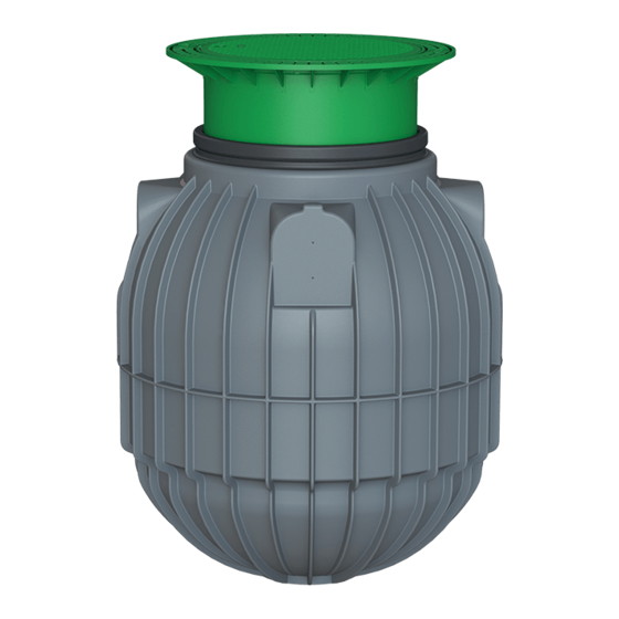
Aufbau Schacht PE-Deckel Teleskop-Domschacht Teleskop-Domschacht (um 5° neigbar) Profildichtung SAPHIR Universalschacht Einbau und Montage Erdreich Deckschicht Teleskop-Domschacht SAPHIR Universalschacht verdichteter Unterbau Betonschicht, bei befahrenen Flächen Umhüllung (Rundkornkies max. Körnung Auf dichte Verfüllung im unteren Drittel des 8/16) Schachtes ist besonders zu achten ß... -
Página 9: Baugrund
Einbau und Montage Baugrund Vor der Installation müssen folgende Punkte unbedingt abgeklärt werden: Die bautechnische Eignung des Bodens nach DIN 18196 • Maximal auftretende Grundwasserstände bzw. Sickerfähigkeit des Untergrundes • Auftretende Belastungsarten, z.B. Verkehrsbelastung • ACHTUNG! LKW-Befahrbarkeit nur in Verbindung mit einer selbsttragenden, eisenarmierten Beton- brücke! - Página 10 über ausreichend große Montageflä- chen mittels GRAF-Spezialdichtungen und KG- >500 Rohren (bauseits zu stellen). Die Öffnungen sind ausschließlich mit dem GRAF- Spezialkronenbohrer in der entsprechenden Größe zu bohren. Es ist darauf zu achten, dass der Ab- stand zwischen den Schächten mind. 500 mm beträgt.
-
Página 11: Einsetzen Und Verfüllen
Einbau und Montage 6.2.6 Einsetzen und Verfüllen Die Schächte sind stoßfrei mit geeignetem Gerät in die vorbereitete Baugrube einzubringen. >300 Um das Eigengewicht des Schachtes bei der Ver- füllung zu erhöhen, werden die Schächte vor dem Anfüllen der Schachtumhüllung zu 1/3 mit Wasser 2. -
Página 12: Montage Teleskop-Domschacht
Montage Teleskop-Domschacht Teleskop-Domschacht montieren Der Teleskop-Domschacht ermöglicht ein stufenlo- ses Anpassen des Schachtes an gegebene Ge- ländeoberflächen zwischen 140 mm und 340 mm (Teleskop-Domschacht Mini) bzw. 140 mm und 440 mm (Teleskop-Domschacht Maxi) Erdüberde- ckung. Zur Montage wird die Profildichtung (Mate- rial EPDM) des Schachtdoms großzügig mit... -
Página 13: Montage Zwischenstück
Montage Zwischenstück Zwischenstück montieren Wird bei größeren Erdüberdeckungen ein Zwischenstück benötigt, wird dieses unter Zuhilfenahme von Schmierseife in den Schachtdom eingesetzt. In die oberste Nut des Zwischenstücks wird die Profildich- tung eingelegt und großzügig eingefettet. Anschließend den Teleskop-Domschacht einschieben und an die geplante Geländeoberfläche anpassen. -
Página 14: 600 L
SAPHIR universal shaft 600 / 900 / 1200 l 600 l Order no. 330455 900 l Order no. 330456 1200 l Order no. 330457 Also for GRAF Saphir M153 sedimentation tanks. 600 L Order no. 330468 900 L Order no. 330469 Order no. 330472 1200 L Order no. -
Página 15: General Information
The shaft cover must always be kept closed, except during work on the shaft, otherwise the risk of acci- dents is high. The fit of the cover should be regularly checked. Only original GRAF covers, or covers ap- proved by GRAF in writing, are to be used. -
Página 16: Transport, Storage And Unloading
Transport, storage and unloading Transport The universal shaft components must be secured to prevent shifting and falling during transport. If the components are secured for transport using tension belts, make sure that they remain undamaged. Stress caused by impacts must be avoided at all costs. Shafts must in no event be rolled or dragged across the ground. -
Página 17: Installation Conditions
Installation conditions Teleskop-Domschacht Teleskop-Domschacht Mini Maxi / Guss Cover heights with telescopic dome shaft (Mini / 140-340 140-440 Maxi) in green area. Mini telescopic dome shaft Maxi / cast telescopic dome shaft max. 1200 Cover heights with extension sleeve and telescop- ic dome shaft, maximum. -
Página 18: Technical Data
Technical data 600 l: 340 (Mini) 440 (Maxi) 440 (Maxi) 1045 1125 900 l: 340 (Mini) 440 (Maxi) 440 (Maxi) 1345 1105 1005 1005 1155 17 / 48... - Página 19 Technical data 1200 l: 340 (Mini) 440 (Maxi) 440 (Maxi) 1670 1430 1330 1330 1155 Shaft 600 l 900 l 1200 l Art. no. 330455 330456 330457 Weight 27 kg 47 kg 58 kg Diameter 1125 mm Diameter 1155 mm...
-
Página 20: Structure Of Shaft
Structure of shaft Telescopic dome shaft PE cover Telescopic dome shaft (tilts by 5°) Profile seal SAPHIR universal shaft Installation and assembly Soil Covering layer Telescopic dome shaft SAPHIR universal shaft Compacted base layer Concrete layer for trafficked areas Surround (round gravel, max. -
Página 21: Foundation
Installation and assembly Foundation The following criteria must be verified prior to installation: The structural suitability of the soil in accordance with DIN 18196 • Maximum groundwater levels / drainage of the subsoil • Types of loading present, e.g. traffic load •... - Página 22 6.2.5 Connecting multiple shafts Two or more shafts can be connected by means of drilling a hole in each tank and installing, GRAF special seals and 110mm underground pipe (pro- >500 vided by the customer).
-
Página 23: Insertion And Filling
Installation and assembly 6.2.6 Insertion and filling The shafts should be carefully lowered into the excavation avoiding any sudden jolts. >300 The shaft must be filled 1/3 full of water before commencing the back filling. The back fill should be carried out using 8 to 16mm single sized gravel 2. -
Página 24: Assembly Of Telescopic Dome Shaft
Assembly of telescopic dome shaft Fitting the telescopic dome shaft The telescopic dome shaft allows the shaft to be smoothly adjusted to the terrain surface between an earth cover of 140 mm and 340 mm (Mini tele- scopic dome shaft) or 140 mm and 440 mm (Maxi telescopic dome shaft). -
Página 25: Assembly Of Spacer
Assembly of spacer Fitting the Extension Sleeve If a spacer is needed for larger earth covers it is inserted into the shaft dome with the aid of soft soap. The profile seal is fitted in the topmost groove of the extension sleeve and greased with plenty of lubri- cant. -
Página 26: 600 L
Stockage ra systématiquement la garantie. Déchargement Lisez également toutes les notices CONDITIONS D'INSTALLATION des autres éléments fournis par la société GRAF. Vous trouverez les DONNEES TECHNIQUES notices de montage jointes dans MONTAGE DU RESERVOIR l’emballage. INSTALLATION / POSE Avant de positionner le réservoir... -
Página 27: Generalite
En dehors de l’entretien du réservoir, le couvercle doit impérativement être verrouillé. Pour des raisons de sécurité, le bon positionnement du couvercle doit être vérifié régulièrement. La société GRAF vous propose une gamme d’accessoires complémentaire et décline toute prise en charge sous garantie en cas d’utilisation d’accessoires non conformes. -
Página 28: Enlevement, Stockage Et Dechargement
Enlèvement, stockage et déchargement Enlèvement Durant le transport, les réservoirs doivent être sécurisés afin de ne pas être endommagés et ne pas glis- ser ou tomber du camion. Si les réservoirs sont arrimés avec des sangles, il faut s’assurer que celles-ci n’ont pas endommagé... -
Página 29: Conditions D'installation
Conditions d'installation Teleskop-Domschacht Teleskop-Domschacht Mini Maxi / Guss 140-340 140-440 Hauteurs de recouvrement avec mini et maxi rehausse télescopique max. 1200 Hauteurs de recouvrement avec maxi rehausse + rallonges (seulement sous les espaces verts – passage piétons uniquement) Hauteurs de recouvrement avec rallonge + re- >400 <1000... -
Página 30: Donnees Techniques
Données techniques 600 L : 340 (Mini) 440 (Maxi) 440 (Maxi) 1045 1125 900 L : 340 (Mini) 440 (Maxi) 440 (Maxi) 1345 1105 1005 1005 1155 29 / 48... - Página 31 Données techniques 1200 L : 340 (Mini) 440 (Maxi) 440 (Maxi) 1670 1430 1330 1330 1155 Réservoir 600 L 900 L 1200 L Référence 330455 330456 330457 Poids 27 kg 47 kg 58 kg Ø 1 125 mm Ø...
-
Página 32: Montage Du Reservoir
Montage du réservoir Couvercle PE Rehausse télescopique Joint EPDM Réservoir SAPHIR Installation / Pose Terre Couche de recouvrement Rehausse télescopique Réservoir SAPHIR Lit de pose en gravier compacté Dalle de répartition béton pour surfaces soumises à un passage véhicules Remblai (gravier rond granulométrie max.8/16... -
Página 33: Terrain
Installation / Pose Terrain Les démarches et études à la parcelle doivent être réalisées conformément à la règlementation en vi- gueur afin d’évaluer les contraintes liées à la nature du sol. Avant l'installation, les points suivants doivent être impérativement vérifiés : La nature du terrain •... -
Página 34: Installation À Proximité De Surface Roulantes (Passage Véhicules)
6.2.5 Jumelage de plusieurs réservoirs Le raccordement de deux ou plusieurs réservoirs s'effectue par le bas à l’emplacement prévu à cet effet à l’aide de joints à lèvres GRAF et tuyaux >500 PVC. Le perçage des réservoirs doit être effectué avec une scie-cloche GRAF. -
Página 35: Mise En Place Et Remplissage
Installation / Pose 6.2.6 Mise en place et remplissage Le réservoir doit être installé dans la fouille grâce à un matériel adapté. >300 Pour éviter toute déformation du réservoir et assu- rer son maintien dans la fouille, remplir d’eau à 1/3, remblayer progressivement par couches succes- 2. -
Página 36: Montage De La Rehausse Telescopique
La couche de béton doit faire au moins 300 mm de largeur et 200 mm de hauteur. Pour un remblai plus important, utilisez la rallonge GRAF (cf.8) Attention: Utiliser impérativement un couvercle fonte Rehausse télescopique passage camions Dans le cas d'une installation avec passage ca- mions, sceller et renforcer la rehausse télesco-... -
Página 37: Montage De La Rallonge
Montage de la rallonge Montage de la rallonge Pour un remblai plus conséquent, il est nécessaire d’utiliser la rallonge munie d’un joint, enduire géné- reusement ce joint après l’avoir monté avec de la graisse blanche. Enduire également de graisse blanche la rehausse télescopique, glisser celle-ci dans le réservoir et ajuster la hauteur au niveau du sol. -
Página 38: 600 L
Excavación MONTAJE DE LA CUBIERTA TELESCÓPICA Si faltaran instrucciones, puede descargarlas desde www.graf.info Montar la cubierta telescópica o solicitarlas a GRAF. Cubierta telescópica transitable Cubierta telescópica transitable por camiones Cubierta telescópica transitable por camiones MONTAJE DE LA EXTENSIÓN Montar la extensión INSPECCIÓN Y MANTENIMIENTO... -
Página 39: Indicaciones Generales
GRAF. GRAF ofrece un amplio surtido de accesorios que han sido adaptados entre sí y que pueden ampliarse para formar sistemas completos. El uso de accesorios no aprobados por GRAF da lugar a la pérdida de la garantía legal/comercial. -
Página 40: Transporte, Almacenamiento Y Descarga
Transporte, almacenamiento y descarga Transporte Durante el transporte deben asegurarse los componentes de la arqueta universal contra deslizamientos y caídas. Si se aseguran los componentes con cintas de amarre para su transporte, debe garantizarse que no sufrirán daños. -
Página 41: Condiciones Para La Instalación
Condiciones para la instalación Cubierta telescópica Teleskop-Domschacht Teleskop-Domschacht Cubierta telescópica Mini Maxi / hierro colado Mini Maxi / Guss 140-340 140-440 Alturas de cobertura para cubierta telescópica (Mini o Maxi) en zonas verdes. max. 1200 Alturas de cobertura máximas para extensiones y cubierta telescópica. -
Página 42: Datos Técnicos
Datos técnicos 600 L: 340 (Mini) 440 (Maxi) 440 (Maxi) 1045 1125 900 L: 340 (Mini) 440 (Maxi) 440 (Maxi) 1345 1105 1005 1005 1155 41 / 48... - Página 43 Datos técnicos 1200 L: 340 (Mini) 440 (Maxi) 440 (Maxi) 1670 1430 1330 1330 1155 Arqueta 600 L 900 L 1200 L Código 330455 330456 330457 Peso 27 kg 47 kg 58 kg Longitud Ø 1125 mm Ø 1155 mm Ø...
-
Página 44: Componentes De La Arqueta
Componentes de la arqueta Tapa de PE de cubierta telescópica Cubierta telescópica (inclinable en 5°) Junta perfilada Arqueta universal SAPHIR Instalación y montaje Suelo Capa de cobertura Cubierta telescópica Arqueta universal SAPHIR Base compactada Capa de hormigón, en el caso de áreas transitadas Capa envolvente (grava redonda tamaño máx. -
Página 45: Terreno
Instalación y montaje Terreno Antes de proceder a la instalación hay que clarificar sin falta los puntos siguientes: La idoneidad según DIN 18196 del suelo para la obra • Los niveles máximos que pueden darse de las aguas subterráneas, así como la capacidad de •... -
Página 46: Instalación En La Vía Tránsito De Camiones
Para la interconexión se utilizan juntas especiales >500 de GRAF y tubos para saneamiento (no incluidos). Las aberturas se realizarán siempre con la corona especial de GRAF del tamaño correspondiente. Respetar una distancia mínima entre las arquetas de 500 mm. -
Página 47: Colocación Y Rellenado
Instalación y montaje 6.2.6 Colocación y rellenado Introducir las arquetas con un equipo adecuado en la excavación preparada, procurando que no sufran golpes. >300 Para aumentar el peso propio de la arqueta durante el rellenado se llena la arqueta hasta 1/3 de su capacidad con agua antes de aplicar la capa 2. -
Página 48: Montaje De La Cubierta Telescópica
Montaje de la cubierta telescópica Montar la cubierta telescópica La cubierta telescópica permite adaptar la arqueta sin solución de continuidad entre 140 y 340 mm (cubierta telescópica Mini) o entre 140 y 440 mm (cubierta telescópica Maxi) a la superficie del terreno. Para montar la junta perfilada (de material EPDM) de la cubierta telescópica se aplica una cantidad generosa... -
Página 49: Montaje De La Extensión
Montaje de la extensión Montar la extensión Si por ser la cobertura de la arqueta grande se precisa una extensión, se encajará la misma en la cubierta con ayuda de jabón blando. Se encaja la junta perfilada en la ranura superior de la extensión y se engrasa la misma con una cantidad generosa de jabón. - Página 50 Notizen / Notes / Notas...