Publicidad
Enlaces rápidos
http://waterheatertimer.org/Safe-electric-wiring.html
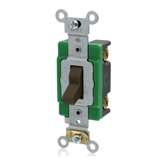
Extra Heavy Duty Industrial Spec Grade
INSTALLATION INSTRUCTIONS
Rated: 30A-120/277V AC
Cat. No. 3031-2, 3031-LH, 3031-PL
Rated: 30A-120V AC
Double Pole Pilot Light
Cat. No. 3032-PL
Dispositif ultra robuste de qualité industrielle
DIRECTIVES
Valeurs nominales : 30 A-120/277 V c.a.
Modèles unipolaires
N
os
3031-2, 3130-LH, 3031-PL
Modèles bipolaires
Modèles à trois voies
Valeurs nominales : 30 A-120 V c.a.
Interrupteur bipolaire à levier lumineux
Especificaciones Grado Industrial Trabajo
INSTRUCCIONES DE INSTALACION
Capacidad: 30A-120/277VCA
No. de Cat. 3031-2, 3031-LH, 3031-PL
No. de Cat. 3032-2
No. de Cat. 3033-2
Capacidad: 30A-120VCA
Interruptor Luz Piloto, Bipolar
No. de Cat. 3032-PL
PK-93022-10-02-0A
WARNING: TO AVOID FIRE,
SHOCK, OR DEATH; TURN OFF
POWER AT CIRCUIT BREAKER OR
FUSE AND TEST THAT POWER IS
Single pole
OFF BEFORE WIRING!
WARNING: TO BE INSTALLED
Double Pole
AND/OR USED IN ACCORDANCE
Cat. No. 3032-2
WITH APPROPRIATE ELECTRICAL
3-Way
Cat. No. 3033-2
CODES AND REGULATIONS.
WARNING: IF YOU ARE NOT SURE
ABOUT ANY PART OF THESE
INSTRUCTIONS, CONSULT AN
ELECTRICIAN.
CAUTION: USE THIS DEVICE WITH
COPPER OR COPPER CLAD WIRE
ONLY.
NOTE: Back and side wire terminals
accept up to #10 AWG copper or
N
o
3032-2
copper clad wire.
TO INSTALL:
N
o
3033-2
1. Remove existing wallplate and
switch or dimmer, if applicable.
N
o
3032-PL
2. (A) To Side Wire: Remove
insulation from each circuit
conductor approx. 3/4" (1.9 cm).
Superpesado
Connect wires per appropriate
WIRING DIAGRAM as follows:
Loop wires clockwise 3/4 turn
Unipolar
around terminal screws. FIRMLY
Dos Polos
tighten screws over wire loop.
2. (B) To Back Wire: Remove
3-Vías
insulation from each circuit
conductor per strip gauge on
device [approx. 1/2" (1.3 cm)].
Connect wires per appropriate
WIRING DIAGRAM as follows:
ENGLISH
Insert straight wires into holes next
to appropriate terminal screws.
Tighten screws FIRMLY.
Side Wire
A
Back Wire
B
3. Using the long mounting screws
provided, mount device into outlet
box. Mount wallplate and tighten
cover screws.
4. Restore power at circuit breaker
or fuse.
Installation is complete.
For Technical Assistance Call:
1-800-824-3005
Publicidad

Resumen de contenidos para Leviton 3031-2
- Página 1 3. Using the long mounting screws Capacidad: 30A-120/277VCA Loop wires clockwise 3/4 turn Unipolar provided, mount device into outlet No. de Cat. 3031-2, 3031-LH, 3031-PL around terminal screws. FIRMLY box. Mount wallplate and tighten Dos Polos tighten screws over wire loop.
- Página 2 Ground (Green Screw) Line Hot (Brass Screw) Terre (vis verte) Ligne active (vis laiton) Load Tierra (Tornillo Verde) Linea Fase (Tornillo de latón) Charge Carga Neutral (White) Load (Brass Screw) Neutre (blanc) Charge (vis laiton) Neutro (Blanco) Carga (Tornillo de latón) Single Pole &...
- Página 3 LIMITED TEN YEAR WARRANTY AND EXCLUSIONS Leviton warrants to the original consumer purchaser and not for the benefit of anyone else that this product at the time of its sale by Leviton is free of defects in materials and workmanship under normal and proper use for ten years from the purchase date. Leviton’s only obligation is to correct such defects by repair or replacement, at its option, if within such ten year period the product is returned prepaid, with proof of purchase date, and a description of the problem to Leviton Manufacturing Co., Inc., Att: Quality Assurance Department, 201 North Service Road, Melville,...


