Publicidad
Idiomas disponibles
Idiomas disponibles
Enlaces rápidos
SLAL -250-PDKIT
Pocket Door Frame Hardware
INSTA L L AT ION INST RUC T ION
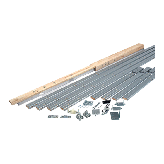
Kit Includes:
(1) Header Track Assembly
(4} Split Jambs
(2) Floor Brackets
(2) Door Plates
(2) Ball Bearing Hangers
(2) End Brackets
(1) Bumper
(1) Wrench
(2) Nylon Door Guides
(1) Adjustable Door Guides
(1) In-Track Stop
Optional Items
•
Bottom Channel Guide
•
Soft Close
•
Floor Guide
Opening End
Pocket End
End
Bracket
Track
Bumper
Finished Floor
Fasteners:
(12) #10 x 1 1/2" Screws
(54) #8 x 5/8" Screws
(18) 2" Nails
Rough Header
End
Bracket
Nailing Strips
Header
2-1/8" Wide
Temporary Brace
Split Jambs
Floor Brackets
Nailing Boards
3-1/2"
Outside to Outside
2"
Inside to Inside
1. Preparing Rough Opening:
Determine the minimum height required from
floor to Rough Header by calculating the door
height plus 4 1/2". Calculate frame width by
multiplying door width by 2 and adding 1 1/4". This
extra 1 1/4" will be filled with the Finish Jambs and
Finish Flat Jamb (refer to step 12).
Example:
Door Height: 80" + 4 1/2" = 84 1/2"
Door Width: 30" x 2 + 1 1/4" = 61 1/4"
Floor Clearances using above dimensions:
Floor Guide allows 3/8"
Wall Mounted Guide allows 3/4"
For the complete list of
GapGuard™ Fire Door
Accessories, the most
up-to-date product
information and installation
instructions, scan the QR
code or visit ngp.com.
Splice
Channel
Outside
Side
View
View
Inside
View
1-3/8" Door
Split Stud
5/16"
clearance
both sides
of door
2"
1-3/4" Door
Split Stud
1/8"
clearance
both sides
of door
2"
Doorway End
Header and
Track Assembly
Split Stud
5/16"
clearance
both sides
of door
Split Stud
1/8"
clearance
both sides
of door
Publicidad

Resumen de contenidos para NGP SLAL-250-PDKIT
- Página 1 For the complete list of GapGuard™ Fire Door Accessories, the most up-to-date product information and installation instructions, scan the QR code or visit ngp.com. SLAL -250-PDKIT Pocket Door Frame Hardware INSTA L L AT ION INST RUC T ION Kit Includes: Fasteners:...
- Página 2 Opening End 2. Cutting Header 30" 36" 32" 28" If door width does not match pre-marked widths, follow 24" instructions for "Cutting Header for Odd-sized Doors" in the next step. Track 24" 32" 28" The Header Track Assembly does not require cutting 2"...
- Página 3 6. Installing Header Track Assembly a) Measuring from floor up set nails at door height + 1/8" on Jamb both side jambs-leaving 1/8" of nail protruding from side End Bracket jambs; bracket will rest on these nails. b) Slide End Brackets onto protruding nails. c) Level Header Track Assembly.
- Página 4 10. Installing Door Plates on Door Panel Position both Door Plates on top side of door panel at least 1 3/4" in from left and right edges of door panel as shown. Secure Door Plates to top of door panel using eight (8) #10 x 1 1/2" screws, 4 for each door plate.
- Página 5 14. Installing Door Trim a) Adjust Door Guides before installing trim. Install door trim over Door Guides allowing 3/16" clearance between door and guide. b) Install In-Track Stop at desired location. Door Guides 15. Optional Items • Install Floor Guide inside Pocket at desired location. Door must be mortised 3/8"...
- Página 6 NGP-SLI-SLAL-250-PDKIT-PRI-0721-A ngp.com NGP MEMPHIS NGP VEGAS 4985 East Raines Road 4584 Calimesa Street Memphis, TN 38118 Las Vegas, NV 89115 1-800-NGP-RUSH orders@ngp.com vegasorders@ngp.com...
-
Página 7: Herraje Para Marco De Puerta Corrediza Empotrada
Aluminio para Puertas Corredizas, información actualizada de los productos e instrucciones de instalación, escanee el código QR o visite ngp.com SLAL -250-PDKIT Herraje Para Marco de Puerta Corrediza Empotrada INST RUCCION ES DE INSTA L ACION Extremo de la Puerta... - Página 8 Extremo de Apertura 2. Corte del Cabezal 30" 36" 32" 28" Si el ancho de la puerta no coincide con los anchos pre- 24" marcados siga las instrucciones “Corte del Cabezal para Puertas de tamaño poco común” en el siguiente paso. Riel 24"...
- Página 9 6. Instalación del Montaje de Riel de Cabezal a) Midiendo del piso hacia arriba ponga los clavos a la Jamba altura de la puerta más + 1/8" en las jambas de ambos Abrazadera de Extremo lados, dejando que el clavo sobresalga 1/8" de la jamba; la abrazadera se apoyará...
- Página 10 Instalación Temporal de la Abrazadera (Paso Opcional) Jambas Divididas Inserte una tabla de 1" x 2 1/8" a través de las Jambas Divididas, descanse la tabla en el Tope y clave una pata de Pata de Apoyo apoyo a la tabla, como se muestra. Esta abrazadera es para Abrazadera agregar soporte durante la instalación de la tablaroca, el Temporal...
-
Página 11: Instale La Guía Del Canal Inferior En La Parte Inferior
13. Instalación de la Guía de Puerta Guía de Puerta Jamba Con las guías de nylon viendo hacia la apertura de la puerta, Dividida asegure la Guía de Puerta a la Jamba Dividida usando tornillos #8 x 1", como se muestra. Opcional •... - Página 12 NGP-SLI-SLAL-250-PDKIT-PRI-0721-A ngp.com NGP MEMPHIS NGP VEGAS 4985 East Raines Road 4584 Calimesa Street Memphis, TN 38118 Las Vegas, NV 89115 1-800-NGP-RUSH orders@ngp.com vegasorders@ngp.com...


