Tabla de contenido
Publicidad
Idiomas disponibles
Idiomas disponibles
Enlaces rápidos
Publicidad
Capítulos
Tabla de contenido

Manuales relacionados para AERMEC Srp ELESTA DOMOTESTA 300


Resumen de contenidos para AERMEC Srp ELESTA DOMOTESTA 300
- Página 1 USAGE MANUAL Electrical regulation for coolers and air-cooled heat pumps with high efficiency scroll type compressor MANUAL DE USO Regulación eléctrica para enfriadoras y bombas de calor condensadas por aria con compresor scroll de alta eficacia ISO 9001 - Cert. n° 0128/4 ISRPFV.
-
Página 3: Tabla De Contenido
Table of contents System types User interface Use of the regulations Operation messages Error messages... - Página 4 "I70: SYSTEM WITHOUT STORAGE"...
- Página 5 CLAMP DESCRIPTION POSITION 21-22 TASRP Room thermostat ACCESSORY A shielded cable is advised for internal supplied without connection cable use . For further information see page TADSRP 23 or the instructions of the accessory Yellow signal cable n°6 - Clamp Antifreeze probe To the SRP board yellow terminal board S6 SUW...
- Página 6 "I71: DIRECT WITH DHW STORAGE TANK" HK/MK...
- Página 7 POSITION CLAMP DESCRIPTION 21-22 TASRP Room thermostat ACCESSORY A shielded cable is advised for internal supplied without connection cable use . For further information see page TADSRP 23 or the instructions of the accessory Yellow signal cable n°6 - Clamp S6 SUW Antifreeze probe To the SRP board yellow terminal board...
-
Página 8: System Types
"72: WITH DHW STORAGE + STORAGE TANK"... - Página 9 CLAMP DESCRIPTION POSITION Room thermostat ACCESSORY A shielded cable is advised for internal 21-22 TASRP supplied without connection cable use . For further information see page TADSRP 23 or the instructions of the accessory Yellow signal cable n°6 - Clamp S6 SUW Antifreeze probe To the SRP board yellow terminal board...
- Página 10 "I74: WITH COMBI TANK"...
- Página 11 LEGEND POSITION CLAMP DESCRIPTION 21-22 TASRP Room thermostat ACCESSORY A shielded cable is advised for internal supplied without connection cable use . For further information see page TADSRP 23 or the instructions of the accessory Yellow signal cable n°6 - Clamp S6 SUW Antifreeze probe To the SRP board yellow terminal board...
-
Página 12: User Interface
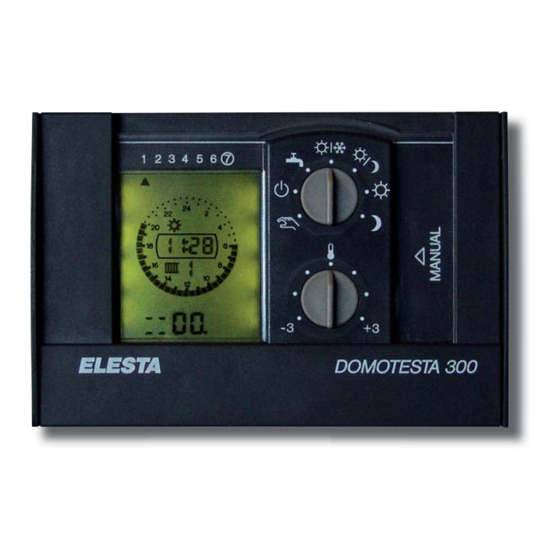
User interface DAY INDICATION OPERATION DISPLAY 1 2 3 4 5 6 7 Dat. Dat. PANEL USER MANAGEMENT MANAGEABLE FUNCTIONS Service PC-Sercvice PROGRAMMING PANEL USER MANAGEMENT PANEL Table Functions of con- tents Manual program; this program foresees that the zone pumps are active and the mixing valves are without voltage (OPEN);... - Página 13 PROGRAMMING PANEL PC-Sercvice Table Functions of con- tents Function selection key (the manageable functions are indicated in table C) Key to select the zone to be set Key to set the day of the week, for the functions that include timing Key to select the parameters related to the selected function Key to decrease the selected value Key to increase the selected value...
- Página 14 OPERATION DISPLAY Table Functions of con- tents Indicates the status of the Q6 and Q7 relay contact outputs (corresponding to terminals 6 and 7 shown on the wiring dia- grams); the up-arrow indicates that the Q6 output is active, while the down-arrow indicates that the Q7 output is active. Function not used Heat pump unit in operation (first stage) Function not used...
-
Página 15: Use Of The Regulations
Use of the regulations Find below the description of the ope- • Direct selections (they can be perfor- Remember that according to the system rations that the user can perform on the med from the user management panel, type (as indicated on page 3/6) in regulation to control/set the SRP unit page 4;... - Página 16 NORMAL/ANTIFREEZE AUTOMATIC PROGRAM The SRP unit is ON (in normal or frost mode) according to the time switch program that is set; the zones are managed according to the time switch program; the boiler charge is ON according to the set- tings of the time switch program corresponding to its management.
- Página 17 • Change of the value set for the zone temperature set: ZONE TEMPERATURE SET CHANGE It is possible to modify the temperature set established for the zone, using the potentiometer indicated in the figure; the setting carried out with this command has been conceived as correction to the set value;...
- Página 18 Dat. HOLIDAY PROGRAM CHANGE/SETTING To access the holiday program setting function, press ( ) until it is placed next to the icon shown in the figure; when this key is pressed, the (A) signal symbol will be displayed to the right of the function 1 2 3 4 5 6 7 printed on the left side of the regulation (page 5 MANAGEABLE Dat.
- Página 19 ZONES TIME SWITCH PROGRAM CHANGE/SETTING To access the zones time switch program setting function, press ) until it is placed next to the icon shown in the figure; when this key is pressed, the (A) signal symbol will be displayed to the right of the function printed on the left side of the regulation;...
- Página 20 BOILER TIME SWITCH PROGRAM CHANGE/SETTING To access the boiler time switch program setting function, press ) until it is placed next to the icon shown in the figure; when this key is pressed, the (A) signal symbol will be displayed to the right of the function printed on the left side of the regulation;...
- Página 21 ZONES SET POINT PROGRAM CHANGE/SETTING In this section it is possible to set the desired temperature for the different operation modes (normal , reduced antifreeze ); the procedure to set the temperature is the following: 1 2 3 4 5 6 7 Dat.
- Página 22 MODIFICATION OF THE OUTSIDE AIR TEMPERATURE CORRECTION CURVE In this section it is possible to set the correction to be applied to the ambient air probe reading; The procedure to set the correction is the following: Press ( ) until reaching the symbol indicated in the figure 1 2 3 4 5 6 7 Dat.
- Página 23 FLOOR DRYING PROGRAM SETTING This function is used to start the drying floor program; this is a special program that is included in case systems with radiating panels are installed; this program must be set by 1 2 3 4 5 6 7 selecting the A2 (B) parameter (the mode with which the Dat.
-
Página 24: Operation Messages
OPERATION MESSAGES The electronic control indicates the different operation modes of the unit and the system to the user;for this, some codes are used to identify the operation mode or current errors; all these messages are displayed on the main screen (shown on page 6 of this manual;... -
Página 25: Error Messages
ERROR MESSAGES The electronic control indicates the different operation modes of the unit and the system to the user; for this, some codes are used to identify the operation mode or current errors; all these messages are displayed on the main screen (shown on page 6 of this manual);... - Página 27 Índice Índice Tipologías de instalación Interfaz del usuario Uso de los ajustes Mensajes de funcionamiento Mensajes de error...
- Página 28 "I70: INSTALACIÓN SIN ACUMULACIÓN ACS"...
- Página 29 LEYENDA DOVE VA POSIZIONATO MORSETTO DESCRIZIONE Termostatos ambiente ACCESORIO 21-22 TASRP TADSRP S6 SUW Sonda anti-hielo borne cable señal amarillo n°6 Al quadro SRP morsettiera gialla Cavo segnale giallo n°5 - Morsetto Presótato de baja Al quadro SRP morsettiera gialla S5 BP Segnale giallo Cavo segnale giallo n°4 - Morsetto...
- Página 30 "I71: INSTALACIÓN CON ACUMULACIÓN ACS" HK/MK...
- Página 31 LEGENDA DOVE VA POSIZIONATO MORSETTO DESCRIZIONE Termostato ambiente ACCESSORIO Si consiglia l'uso di un cavo scherma- 21-22 TASRP fornito privo di cavo di collega- to per utilizzo interno . Per maggiori mento informazioni vedere pagina 23 oppure TADSRP l'struzione dell'accessorio Cavo segnale giallo n°6 - Morsetto S6 SUW Sonda antigelo...
-
Página 32: Tipologías De Instalación
"I72: CON SERBATOIO SANITARIO ACS E ACCUMULO"... - Página 33 LEGENDA MORSETTO DESCRIZIONE DOVE VA POSIZIONATO 21-22 TASRP Termostato ambiente ACCESSORIO Si consiglia l'uso di un cavo scherma- fornito privo di cavo di collega- to per utilizzo interno . Per maggiori TADSRP mento informazioni vedere pagina 23 oppure l'struzione dell'accessorio Cavo segnale giallo n°6 - Morsetto Sonda antigelo Al quadro SRP morsettiera gialla...
- Página 34 "I74: VERSIONE CON CALDAIA"...
- Página 35 LEGENDA MORSETTO DESCRIZIONE DOVE VA POSIZIONATO 21-22 TASRP Termostato ambiente ACCESSORIO Si consiglia l'uso di un cavo scherma- fornito privo di cavo di collega- to per utilizzo interno . Per maggiori TADSRP mento informazioni vedere pagina 23 oppure l'struzione dell'accessorio Cavo segnale giallo n°6 - Morsetto Sonda antigelo Al quadro SRP morsettiera gialla...
-
Página 36: Panel De Gestión Usuario
Interfaz del usuario INDICACIÓN DÍA PANTALLA FUNCIONAMIENTO 1 2 3 4 5 6 7 Dat. Dat. PANEL GESTIÓN USUARIO FUNCIONES CONTROLABLES Service PC-Sercvice PANEL DE PROGRAMACIÓN PANEL DE GESTIÓN USUARIO Índice Funciones Selección programa manual; dicho programa prevé que las bombas de zona estén activas y que las vál- vulas mezcladoras no tengan tensión (ABIERTAS);... -
Página 37: Panel De Programación
PANEL DE PROGRAMACIÓN PC-Sercvice Índice Funciones Tecla de selección de las funciones (las funciones controlables se indican en la tabla C) Tecla de selección de la zona a configurar Tecla de configuración del día de la semana, para las funciones que prevén una temporización Tecla de selección de los parámetros referidos a la función seleccionada Tecla para la disminución del valor seleccionado Tecla para el aumento del valor seleccionado... -
Página 38: Pantalla Funcionamiento
PANTALLA FUNCIONAMIENTO Índice Funciones Indica el estado de la salida del contacto relé Q6 y Q7 (referidos a los bornes 6 y 7 evidenciados en los esquemas eléctri- cos), la flecha hacia arriba indica que está activa la salida Q6, mientras que la flecha hacia abajo indica que está activa la salida Q7. -
Página 39: Uso De Los Ajustes
Uso de los ajustes A continuación, se indican las opera- • Selecciones directas (realizables Recordar que en base a la tipología de ciones que el usuario puede realizar desde el panel gestión usuario pág. 4, o la instalación (como se indica en pág. sobre el ajuste para controlar/establecer desde el termostato a distancia);... -
Página 40: Programa Automático Normal/Antihielo
PROGRAMA AUTOMÁTICO NORMAL/ANTIHIELO La unidad SRP está ON (en modalidad normal o antihielo) de acuerdo al programa horario configurado; las zonas se controlan en base al programa horario; la carga del hervidor está ON en base a las confi- guraciones del programa horario correspondiente a su gestión. DOMOTESTA 300 PROGRAMA AUTOMÁTICO NORMAL/REDUCIDO La unidad SRP está... -
Página 41: Modificación Configuración Temperatura De Zona
• Modificación del valor establecido para la configuración de la temperatura de zona: MODIFICACIÓN CONFIGURACIÓN TEMPERATURA DE ZONA Es posible modificar la configuración de la temperatura establecida para la zona, interviniendo sobre el potenciómetro indicado en la figura; la configuración controlada por este mando ha sido concebida como corrección del valor establecido;... -
Página 42: Modificación/Configuración Del Programa Vacaciones
Dat. MODIFICACIÓN/CONFIGURACIÓN DEL PROGRAMA VACACIONES Para ingresar en la función configuración del programa vacaciones, presionar la tecla ( ) hasta posicionarse al lado del icono repre- sentado en la figura; presionando esta tecla, aparecerá el símbolo 1 2 3 4 5 6 7 de señalización (A) a la derecha de la función impresa en el lado Dat. -
Página 43: Modificación/Configuración Del Programa Horario Zonas
MODIFICACIÓN/CONFIGURACIÓN DEL PROGRAMA HORARIO ZONAS Para ingresar en la función configuración del programa horario zonas, presionar la tecla ( ) hasta posicionarse al lado del icono representado en figura; al presionar esta tecla aparecerá el símbo- lo de señalización (A) a la derecha de la función impresa en el lado 1 2 3 4 5 6 7 izquierdo del ajuste;... -
Página 44: Modificación/Configuración Del Programa Horario Hervidor
MODIFICACIÓN/CONFIGURACIÓN DEL PROGRAMA HORARIO HERVIDOR Para ingresar en la función configuración del programa horario hervidor, presionar la tecla ( ) hasta posicionarse al lado del icono representado en figura; al presionar esta tecla aparecerá el símbo- lo de señalización (A) a la derecha de la función impresa en el lado 1 2 3 4 5 6 7 izquierdo del ajuste;... -
Página 45: Modificación/Configuración Del Programa Set Point Zonas
MODIFICACIÓN/CONFIGURACIÓN DEL PROGRAMA SET POINT ZONAS En esta sección es posible configurar la temperatura dese- ada para diferentes modos de funcionamiento (normal reducido , antihielo ); el procedimiento para la confi- guración es el siguiente: 1 2 3 4 5 6 7 Dat. -
Página 46: Modificación De La Curva De Corrección De La Temperatura Externa
MODIFICACIÓN DE LA CURVA DE CORRECCIÓN DE LA TEMPERATURA EXTERNA En esta sección es posible configurar la corrección para aplicar a la lectura de la sonda aire exterior; el procedi- miento para la configuración es el siguiente: Presionar la tecla ( ) hasta alcanzar con el puntero (A) el 1 2 3 4 5 6 7 Dat. -
Página 47: Configuración Programa De Secado De Pisos
CONFIGURACIÓN PROGRAMA DE SECADO DE PISOS Esta función permite iniciar el programa de secado de pisos; este es un programa especial para el caso en que se instalen sistemas con paneles radiantes; este progra- 1 2 3 4 5 6 7 ma debe configurarse seleccionando el parámetro A2 (B) Dat. -
Página 48: Mensajes De Funcionamiento
MENSAJES DE FUNCIONAMIENTO El control electrónico señala al usuario los diferentes estadios de funcionamiento de la unidad y de la instalación; para reali- zar esto, se vale de algunos códigos que identifican la modalidad de funcionamiento o los errores en curso; todos estos men- sajes se visualizan en la pantalla principal (representada en la página 6 de este manual);... -
Página 49: Mensajes De Error
MENSAJES DE ERROR El control electrónico señala al usuario los diferentes estadios de funcionamiento de la unidad y de la instalación; para realizar esto se vale de algunos códigos que identifican la modalidad de funcionamiento o los errores en curso; todos estos mensajes se visualizan en la pantalla principal (representada en la página 6 de este manual);... - Página 52 The technical data in the following documentation are not binding. www .aermec. com Aermec reserves the right to make all the modifications considered necessary for improving the product at any time. Los datos técnicos contenidos en este documento no son vinculantes.