Publicidad
Enlaces rápidos
YC/251
C
1
2
3
4
P1
5
6
BPT YC/251
1
BPT C/251
1
BPT C/200
9
BPT E/200
2
BPT AZ/70
1
BPT AZ/71
1
BPT FD/50
1
BPT FD/51
1
LT 603/N
1
URMET 5800/31
2
ELVOX 870
2
TEGUI HORIZON/N
4
GOLMAR T/810G
5
COMELIT VOX 2100
3
TESLA 4FP/110/36/181 2
FERMAX 2044-20440
2
09.2004/2406-6800
BPT S.p.A.
30020 Cinto Caomaggiore
Venezia - Italy
1
3
SW1
NC
C
P2
2
3
4
5
6
2
3
4
5
6
9
–
5
8
7
2
–
1
3
4
2
3
4
5
2
3
4
5
2
3
4
5
2
3
4
5
T1
6
3
2
–
9
7
6-10-11
1
–
7
6
3-4-5
1
–
3
1
2
5
–
C2
7
3
10
–
P1
1
4
2
–
1
4
3
6
–
1
–
3
6
4
ISTRUZIONI
I
PER L'INSTALLAZIONE
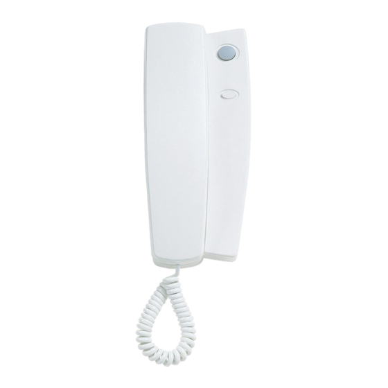
CITOFONO YC/251
Derivato interno universale da parete
munito di comando apriporta
È predisposto per l'inserimento del
pulsante servizi ausiliari (
Può essere installato sia negli impian-
ti citofonici con chiamata elettronica
o con chiamata a ronzatore.
È dotato di 2 potenziometri (fig. 6):
P1, per la regolazione ampiezza
segnale dell'altoparlante del derivato
interno.
P2, per la regolazione segnale del
microfono del derivato interno.
Funzione dei morsetti (fig. 6)
1
microfono
2
comando apriporta
3
chiamata con ronzatore
4
massa
5
altoparlante
6
chiamata elettronica
Funzione del ponticello SW1
Il citofono dispone del ponticello SW1
(fig. 6) per la connessione della
massa microfono alla massa comune
2
(posizione C predefinita) o separata
(NC).
L'apparecchio può sostituire vari
modelli di citofoni in commercio; per i
collegamenti vedere la tabella di fig. 5.
IMPORTANTE. Per sostituire un
citofono FD/50 o FD/51 negli impianti
con posti esterni muniti di amplifica-
tore FD/55, è necessario intervenire
sullo stesso come segue:
- Aprire l'unità dell'apparecchio dove
sono situate le regolazioni audio (fig.
7).
- Tagliare il conduttore blu C (fig. 8)
4
del potenziometro
condensatore elettrolitico da 10µF
5
con tensione di lavoro superiore a 16
V, facendo attenzione che il terminale
negativo del condensatore sia rivolto
verso il potenziometro di regolazione
(fig. 8).
Istruzioni per l'installazione
Dopo aver tolto il mobile (fig. 1) fissa-
re la base direttamente al muro (fig.
2) o alla scatola d'incasso (fig. 3 o 4).
Su pareti non perfettamente piane
evitare il serraggio eccessivo delle
viti.
GND
SW1
C
INSTALLATION
GB
C
INSTRUCTIONS
C
C
YC/251 HANDSET
Universal wall-mounted receiver fea-
C
turing door lock release control
C
It can accommodate the auxiliary
services button (
C
Can be installed in audio entry con-
C
trol systems either with electronic call
or buzzer call.
C
It is fitted with 2 potentiometers, figu-
re 6:
C
P1, for adjusting signal amplitude of
C
receiver's loudspeaker.
P2, for adjusting signal of receiver's
C
microphone.
C
Function of each terminal, figure 6
C
1
microphone
NC
2
door lock release control
3
call with buzzer
4
ground
5
loudspeaker
6
electronic call
Function of jumper SW1
The handset has a jumper SW1 (fig.
.
6) for connecting the microphone's
ground to the common ground (pre-
) YP1.
defined setting C) or for keeping it
separate (NC).
The apparatus may replace various
different handset models currently
available on the market; see the table
in figure 5 for wiring.
IMPORTANT. In order to replace a
FD/50 or FD/51 handset in installa-
tions whose entry panels feature the
amplifier FD/55, the following action
must be taken on said amplifier:
- Open the unit where the apparatus'
audio adjustment device are situa-
ted, figure 7.
- Cut the blue wire C, figure 8, corre-
sponding to the
and connect a 10µF electrolytic
capacitor with a working voltage of
over 16 V, taking care that the capa-
citor's negative terminal is turned
towards the adjustment potentiome-
ter, figure 8.
Installation instructions
First, remove the housing (fig. 1) and
fasten the base directly to the wall
(fig. 2) or to the embedding box (fig.
3 or 4).
If walls are not perfectly level, do not
overtighten screws.
INSTALLATIONS-
D
ANLEITUNG
e collegare un
SPRECHGARNITUR YC/251
Universal-Innensprechstelle für die
Wandmontage, mit Türöffnersteuerung
.
Es ist für den Einsatz der Zusatz-
diensttaste (
Für den Einbau in Haussprechan-
lagen mit elektronischem Ruf oder
Summton.
Ausgestattet mit 2 Potentiometern
(Abb. 6):
P1, für die Regelung der Lautspre-
cherstärke der Innensprechstelle.
P2, für die Regelung des Mikrofon-
signals der Innensprechstelle.
Funktion der Klemmen (Abb. 6)
1
Mikrofon
2
Türöffner
3
Ruf mit Summer
4
Masse
5
Lautsprecher
.
6
Elektronischer Rufton
) YP1.
Belegung
Überbrückungsklemme SW1
Die Sprechgarnitur ist mit der Über-
brückungsklemme SW1 (Abb. 6)
ausgestattet, der den Anschluss zwi-
schen der Mikrofonmasse und der
gemeinsamen (Position C vorgege-
ben) oder getrennten Masse (NC)
herstellt.
Das Gerät kann verschiedene, im
Handel erhältliche Sprechgarnituren
ersetzen; zwecks den Anschlüssen
ist die Tabelle in Abb. 5 zu beachten.
potentiometer,
) YP1.
der
1
Publicidad

Resumen de contenidos para Bpt YC/251
- Página 1 YC/251 ISTRUZIONI ground PER L’INSTALLAZIONE loudspeaker electronic call BPT S.p.A. CITOFONO YC/251 30020 Cinto Caomaggiore Function of jumper SW1 Derivato interno universale da parete Venezia - Italy The handset has a jumper SW1 (fig. munito di comando apriporta 6) for connecting the microphone’s È...
- Página 2 Depois de ter tirado o móvel (fig. 1), tornillos. PARA LA INSTALACION fixar a base directamente ao muro (fig. 2), ou então à caixa de encastre COMBINE YC/251 (fig. 3 ou 4). Poste intérieur mural universel avec TELEFONO YC/251 Sobre paredes não perfeitamente...


