Tabla de contenido
Publicidad
Idiomas disponibles
Idiomas disponibles
Enlaces rápidos
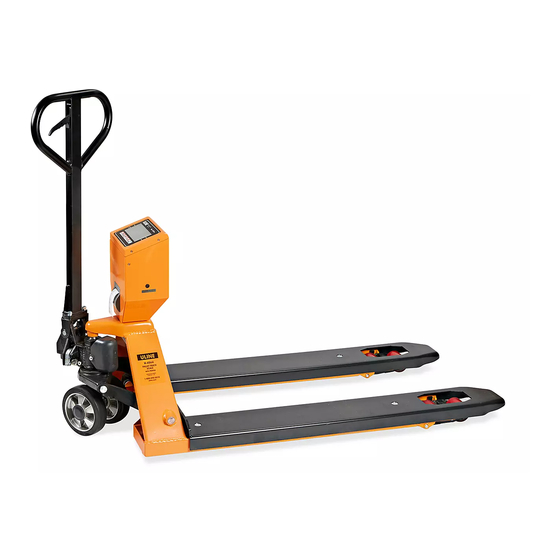
H-4564
PALLET TRUCK SCALE
WITH PRINTER
AVOID PLACING THE SCALE IN LOCATIONS THAT MAY AFFECT ACCURACY:
1. Temperature extremes – Do not place in direct sunlight or near air conditioning vents.
2. Keep scale dry – Do not place in high humidity, damp or wet locations.
3. Keep away from air movers like fans or open doors and windows.
4. Keep scale clean.
5. Do not stack items on the scale when not in use.
WARNING! Scale is not waterproof. Avoid direct contact with water, high
humidity and condensation. Do not spray or immerse scale in water. Data
may become unstable or scale may malfunction. Turn power off and allow
scale to dry before reuse.
1 OF 62
1-800-295-5510
uline.com
GENERAL INFORMATION
Para Español, vea páginas 21-41.
Pour le français, consulter les pages 42-62.
0721 IH-4564
Publicidad
Capítulos
Tabla de contenido

Manuales relacionados para Uline H-4564


Resumen de contenidos para Uline H-4564
- Página 1 Para Español, vea páginas 21-41. Pour le français, consulter les pages 42-62. H-4564 1-800-295-5510 uline.com PALLET TRUCK SCALE WITH PRINTER GENERAL INFORMATION AVOID PLACING THE SCALE IN LOCATIONS THAT MAY AFFECT ACCURACY: 1. Temperature extremes – Do not place in direct sunlight or near air conditioning vents.
-
Página 2: Tabla De Contenido
TABLE OF CONTENTS SPECIFICATIONS LCD DISPLAY DISPLAY CHARACTERS CONTROLS ASSEMBLY SAFETY OPERATION 10-13 BATTERY MAINTENANCE/CALIBRATION PARTS DIAGRAMS 16-19 ERROR CODES 2 OF 62 0721 IH-4564... -
Página 3: Specifications
SPECIFICATIONS H-4564 PALLET TRUCK SCALE Max. Lifting Weight 5,000 lbs. Min. Fork Height 3⁄" 7½" Max. Fork Height Fork Length 48" Fork Overall Width 27" Individual Fork Width 7" Capacity 5,000 lbs. Division 1 lb. External Resolution 1/5,000 Internal Resolution... -
Página 4: Lcd Display
LCD DISPLAY 4 OF 62 0721 IH-4564... -
Página 5: Display Characters
DISPLAY CHARACTERS CHARACTER DISPLAY CHARACTER DISPLAY 5 OF 62 0721 IH-4564... -
Página 6: Controls
CONTROLS primary function secondary function ON/OFF Key: Accumulate Key (M+): Turn the power on or off. Adds the value to the Print accumulation memory. Zero display and press this key to show current total value. Print Key (Print) Prints weight data Zero Key (ZERO): on piece of paper. -
Página 7: Assembly
ASSEMBLY INSTRUCTIONS I. CAREFULLY UNPACK ALL ITEMS 3. Align mounting holes on pallet truck with mounting holes on control panel. 1. Remove control panel from packing (See Figure 4) foam. (See Figure 1) Figure 4 Figure 1 4. Insert and tighten 3 hex screws (H109) with spring washers (H110) through base of control panel with hex wrench II. -
Página 8: Handle Installation
ASSEMBLY INSTRUCTIONS CONTINUED III. HANDLE INSTALLATION 5. Attach handle to base (103) using 3 hex screws (H109) and 3 spring washers 1. Remove handle from protective (H110) and tighten with Hex Wrench wrapping. provided. (See Figure 9) 2. Loosen set screw (140) on crank link (139H). -
Página 9: Safety
SAFETY SAFETY NOTE For safe operation of the truck, please read all warnings and instructions in this guide and on the truck before use. 1. Do not operate the pallet truck unless 6. Do not handle unstable or loosely you are familiar with it and have been stacked loads. -
Página 10: Basic Operations
BASIC OPERATIONS ENSURE FORKS RAISE/LOWER PROPERLY Control Lever (H106) is located on pallet truck handle (H101) and can be set to 3 positions: LOWER, NEUTRAL and ASCENT. 1. Tighten set screw (140) on crank link (139H) until LOWER position on Control Lever functions properly. -
Página 11: Operation
OPERATION CONTROL LEVER removing the container this value is the gross weight of the container plus all product that was The control lever (H106) can be set in three removed. The zero indicator will be on because positions (see below). the pallet is back to the same condition it was when the ZERO key was last pressed. - Página 12 OPERATION CONTINUED MEMORY RECALL Figure 11 To view the totals in memory, press the M+ Paper key while display reads zero, and display will Roll show "AC n" ('n' is current accumulation Cover times) and then the total in memory for 2 seconds.
- Página 13 OPERATION CONTINUED 2. The display will show the first function, "F1 6. Use the "U" key to leave a parameter unit". unchanged. 3. Pressing the TARE key will cycle through the 7. For example when the display shows "F1 other functions. unit"...
-
Página 14: Battery Operation
As the battery is used it may fail to hold scale is plugged in the internal battery will a full charge. If the battery life becomes unacceptable, contact Uline Customer charge. Colors in the LED window indicate Service at 1-800-295-5510. -
Página 15: Maintenance/Calibration
Enter Technical Parameter Setting prevented a successful calibration. If the mode(see steps 1-3 above) until display problem persists, please contact Uline Customer Service. shows "P1 rEF". 2. Press the TARE key until display shows "P2 CAL". -
Página 16: Parts Diagrams
PARTS DIAGRAM DIAG 1 DIAG 2 LOWER position H110 H109 H107 NEUTRAL position ASCENT position H106 H101 139H 122H DIAG 3 139H PART NO. PART NAME QTY. H107 Wire, Chain and Pin H109 Hex Screw H110 Spring Washer 122H Pump Housing 139H Crank Link Base... - Página 17 PARTS DIAGRAM CONTINUED H101 H102 H103 H104 H111 H105 H112 H106 H107 H108 H109 H110 PART NO. PART NAME QTY. H101 Handle H102 Spring Pin H103 Spring Leaf H104 Spring Pin H105 Spring Pin H106 Control Lever H107 Wire, Chain and Pin H108 Rubber Cushion H109...
- Página 18 PARTS DIAGRAM CONTINUED 157-1 158H 159H 108 107 106 105 104 103 160H 161H 162H 163H 164H 112 113 165H 114 115 166 118 139H 122H 154 155 18 OF 62 0721 IH-4564...
-
Página 19: Parts List
PARTS LIST PART NO. PART NAME QTY. PART NO. PART NAME QTY. Steel Ball Screw 139H Crank Link Base Set Screw Steel Roller Bushing Parallel Pin Retaining Cover Shaft Spring Cover Retaining Ring Spring Axle Pump Rod Screw Dust Proof Ring Washer Pump Cylinder Spring... -
Página 20: Error Codes
ERROR CODES ERROR CODES DESCRIPTION RESOLUTION ----- Overload Remove weight from the scale. If the problem persists contact Uline Customer Service. Err 1 Date Setting Error Enter date using correct format. Format: yy:mm:dd Err 2 Time Setting Error Enter time using correct format. -
Página 21: Báscula Con Patín Hidráulicoe Impresora
H-4564 800-295-5510 uline.mx BÁSCULA CON PATÍN HIDRÁULICO E IMPRESORA INFORMACIÓN GENERAL EVITE COLOCAR LA BÁSCULA EN UBICACIONES QUE PUEDAN AFECTAR A LA PRECISIÓN: 1. Temperaturas extremas: No colocar bajo la luz solar directa o cerca de ventilas de aire acondicionado. - Página 22 TABLA DE CONTENIDO ESPECIFICACIONES PANTALLA LCD CARACTERES DE LA PANTALLA CONTROLES ENSAMBLE 27-28 SEGURIDAD FUNCIONAMIENTO 30-34 BATERÍA MANTENIMIENTO/ CALIBRACIÓN DIAGRAMAS DE PARTES 37-40 CÓDIGOS DE ERROR 22 OF 62 0721 IH-4564...
-
Página 23: Especificaciones
ESPECIFICACIONES H-4564 BÁSCULA CON PATÍN HIDRÁULICO Máx. Peso de 2,267 kg (5,000 lbs.) Levantamiento Altura Mín. de Horquilla 8.5 cm (3⁄") Altura Máx. de Horquilla 19 cm (7½") Longitud de Horquilla 1.2 m (48") Ancho Total de Horquilla 68.6 cm (27") Ancho Individual de 17.8 cm (7") -
Página 24: Pantalla Lcd
PANTALLA LCD 24 OF 62 0721 IH-4564... -
Página 25: Caracteres De La Pantalla
CARACTERES DE LA PANTALLA CARÁCTER PANTALLA CARÁCTER PANTALLA 25 OF 62 0721 IH-4564... -
Página 26: Controles
CONTROLES función primaria función secundaria Tecla ON/OFF: Tecla de Acumulación (M+): Enciende o apaga la electricidad. Añade el valor a la memoria de Print acumulación. Ponga la pantalla en ceros y presione esta tecla para mostrar el valor total actual. La tecla de Impresión (Print) Tecla de Cero (ZERO): imprime los datos sobre el pesaje... -
Página 27: Instrucciones De Ensamble
INSTRUCCIONES DE ENSAMBLE I. DESEMPAQUE CON CUIDADO 3. Alinee los orificios de montaje del patín hidráulico con los orificios de montaje del TODOS LOS ARTÍCULOS panel de control. (Vea Diagrama 4) 1. Saque el panel de control de la espuma para empaque. -
Página 28: Continuación De Instrucciones De Ensamblado
CONTINUACIÓN DE INSTRUCCIONES DE ENSAMBLADO III. INSTALACIÓN DEL ASA 5. Fije el asa a la base (103) usando 3 tornillos hexagonales (H109) y 3 1. Saque el asa de su envoltura rondanas de resorte (H110) y apriete protectora. con la Llave Hexagonal que se suministra. -
Página 29: Seguridad
SEGURIDAD NOTA DE SEGURIDAD Para la operación segura del patín, lea todas las instrucciones y advertencias de seguridad que aparecen aquí o en el patín antes de usarlo. 1. No opere el patín hidráulico a menos 6. No maneje cargas inestables ni apiladas esté... -
Página 30: Funcionamiento Básico
FUNCIONAMIENTO BÁSICO ASEGÚRESE DE QUE LAS HORQUILLAS SUBEN/BAJAN CORRECTAMENTE La Palanca de Control (H106) está ubicada en el asa del patín hidráulico (H101) y se puede colocar en 3 posiciones: LOWER (bajar), NEUTRAL (neutro) y ASCENT (elevar). 1. Apriete el tornillo de ajuste (140) sobre el eslabón de la manivela (139H) hasta que la posición LOWER (bajar) LOWER (bajar) de la Palanca de Control funcione... -
Página 31: Funcionamiento
FUNCIONAMIENTO PALANCA DE CONTROL primero. De nuevo, solo se mostrará el peso añadido después de tarar la báscula. La palanca de control (H106) tiene tres Cuando retire el contenedor, se mostrará posiciones (ver abajo). un valor negativo. Si la báscula se ha tarado LOWER (bajar): justo antes de retirar el contenedor, este valor Empuje la palanca... -
Página 32: Continuación De Funcionamiento
CONTINUACIÓN DE FUNCIONAMIENTO 3. El indicador M+ aparece encendido. NOTA: El valor de pretara se muestra mientras que aparece el indicador de Quite el peso, permita que la báscula NET (neto) en la pantalla. vuelva a cero y coloque un segundo peso en la báscula. -
Página 33: Formatos De Impresión
CONTINUACIÓN DE FUNCIONAMIENTO PARÁMETROS 2. Inserte el rollo de papel. Inserte el extremo del rollo de papel a través de la cubierta. (Vea Diagrama 12) La báscula dispone de parámetros que el usuario puede establecer. 1. Para establecer parámetros, presione a la Papel Diagrama 12 vez las teclas ZERO (cero) y TARE (tara). -
Página 34: Descripción
CONTINUACIÓN DE FUNCIONAMIENTO TABLA DE CONFIGURACIÓN DE FUNCIONES FUNCIÓN FUNCIÓN DESCRIPCIÓN VALOR PREDETERMINADO SECUNDARIA F1 u nt Configura la unidad de pesaje mostrada. kg/lbs. Seleccionar entre kg/lbs. F2 dat La báscula mostrará en principio a-m-d o d-m-a, que equivale 2000/01/01 al formato de la fecha (año-mes-día o día-mes-año). -
Página 35: Batería
Los colores de la ventana LED indican el completa. Si la vida útil de la batería se torna inaceptable, llame a la línea estado de la batería: de Servicio a Clientes de Uline al • Verde: La batería está completamente 01-800-295-5510. -
Página 36: Mantenimiento
ZERO (cero) para ingresar y presione éxito. Si el problema continúa, llame a la la tecla TARE (tara) hasta que la pantalla línea de Servicio a Clientes de Uline. muestre "CAL". 36 OF 62 0721 IH-4564... - Página 37 DIAGRAMA DE PARTES DIAG 1 DIAG 2 Posición LOWER (bajar) H110 H109 H107 Posición NEUTRAL (neutral) Posición ASCENT (elevar) H106 H101 139H 122H DIAG 3 139H NO. DE PARTE NOMBRE DE LA PARTE CANT. H107 Alambre, Cadena y Pasador H109 Tornillo Hexagonal H110 Rondana con Resorte...
-
Página 38: Continuación De Diagrama De Partes
CONTINUACIÓN DE DIAGRAMA DE PARTES H101 H102 H103 H104 H111 H105 H112 H106 H107 H108 H109 H110 NO. DE PARTE NOMBRE DE LA PARTE CANT. H101 H102 Pasador con Resorte H103 Resorte de Ballesta H104 Pasador con Resorte H105 Pasador con Resorte H106 Palanca de Control H107... - Página 39 CONTINUACIÓN DE DIAGRAMA DE PARTES 157-1 158H 159H 108 107 106 105 104 103 160H 161H 162H 163H 164H 112 113 165H 114 115 166 118 139H 122H 154 155 39 OF 62 0721 IH-4564...
-
Página 40: Lista De Partes
LISTA DE PARTES NO. DE PARTE NOMBRE DE LA PARTE CANT. NO. DE PARTE NOMBRE DE LA PARTE CANT. Bola de Acero Tornillo Varilla 139H Eslabón de la Manivela Base Tornillo de Ajuste Rodillo de Acero Tuerca Buje Pasador Paralelo Pasador Cubierta de Fijación Cubierta de Resorte... -
Página 41: Códigos De Error
DESCRIPCIÓN RESOLUCIÓN ----- Sobrecarga Quite el peso de la báscula. Si el problema continúa, llame a la línea de Servicio a Clientes de Uline. Err 1 Error en la configuración Ingrese la fecha con el formato de la fecha correcto. -
Página 42: Renseignements Généraux
H-4564 1-800-295-5510 uline.ca TRANSPALETTE PESEUR AVEC IMPRIMANTE RENSEIGNEMENTS GÉNÉRAUX ÉVITEZ DE PLACER LA BALANCE DANS DES ENDROITS OÙ SA PRÉCISION PEUT ÊTRE COMPROMISE : 1. Températures extrêmes : ne placez pas la balance au soleil ou près de bouches de climatisation. 2. Maintenez la balance sèche : ne placez pas la balance dans des endroits très humides ou mouillés. - Página 43 TABLE DES MATIÈRES SPÉCIFICATIONS ÉCRAN D'AFFICHAGE ACL CARACTÈRES D'AFFICHAGE COMMANDES ASSEMBLAGE 48-49 SÉCURITÉ FONCTIONNEMENT 51-55 BATTERIE ENTRETIEN/ÉTALONNAGE SCHÉMAS DES PIÈCES 58-61 CODES D'ERREUR 43 OF 62 0721 IH-4564...
-
Página 44: Spécifications
SPÉCIFICATIONS TRANSPALETTE PESEUR H-4564 Poids de levage maximal 2 268,0 kg (5 000 lb) Hauteur min. des fourches 8,5 cm (3 ⁄ po) Hauteur max. des fourches 19 cm (7 ½ po) Longueur des fourches 1,2 m (48 po) Largeur totale des fourches 68,6 cm (27 po) Largeur d'une fourche 17,8 cm (7 po) -
Página 45: Écran D'affichage Acl
AFFICHAGE ACL 45 OF 62 0721 IH-4564... -
Página 46: Caractères D'affichage
CARACTÈRES D'AFFICHAGE CARACTÈRE AFFICHAGE CARACTÈRE AFFICHAGE 46 OF 62 0721 IH-4564... -
Página 47: Commandes
COMMANDES fonction principale fonction auxiliaire Touche ON/OFF (marche/arrêt) : Touche d'accumulation (M+) : Allume ou éteint l'alimentation. Ajoute la valeur à la mémoire Print accumulée. Réinitialisez l'affichage et appuyez sur cette touche pour afficher la valeur totale actuelle. La touche d'impression (Print) Touche zéro (ZERO) : imprime les données de poids sur Réinitialise l'affichage pour le... -
Página 48: Instructions D'assemblage
INSTRUCTIONS D'ASSEMBLAGE I. DÉBALLEZ SOIGNEUSEMENT TOUS 3. Alignez les trous de montage du transpalette avec ceux du panneau de LES ÉLÉMENTS commande. (Voir Figure 4) 1. Retirez le panneau de commande de la mousse d'emballage. (Voir Figure 1) Figure 4 Figure 1 4. À l'aide de la clé hexagonale fournie, insérez et serrez trois (3) vis hexagonales (H109) et des rondelles à... -
Página 49: Installation De La Poignée
INSTRUCTIONS D'ASSEMBLAGE SUITE III. INSTALLATION DE LA POIGNÉE 5. À l'aide de trois (3) vis hexagonales (H109) et trois (3) rondelles à ressort 1. Retirez la poignée de l'emballage (H110), fixez la poignée à la base (103), protecteur. et serrez à l’aide de la clé hexagonale fournie. -
Página 50: Sécurité
SÉCURITÉ REMARQUES PORTANT SUR LA SÉCURITÉ Afin d'assurer un fonctionnement sécuritaire du transpalette, veuillez lire tous les avertissements et consignes qui figurent dans ce guide et sur le transpalette avant l'utilisation. 1. N'utilisez pas le transpalette si vous 6. Ne manutentionnez jamais des charges n'avez pas une bonne connaissance de instables ou mal empilées. -
Página 51: Fonctionnement De Base
FONCTIONNEMENT DE BASE S'ASSURER QUE LES FOURCHES SE LÈVENT ET S'ABAISSENT ADÉQUATEMENT Le levier de commande (H106) est situé sur la poignée (H101) du transpalette et peut prendre trois (3) positions : LOWER, NEUTRAL et ASCENT (DESCENDANT, NEUTRE et ASCENDANT) 1. Serrez la vis de réglage (140) sur la LOWER (BAISSER) NEUT manivelle (139H) jusqu'à... -
Página 52: Fonctionnement
FONCTIONNEMENT LEVIER DE COMMANDE Lorsque le bac est retiré, une valeur négative s'affiche. Si la balance est tarée juste avant de Le levier de commande (H106) peut être retirer le bac, cette valeur est le poids brut du réglé dans trois positions (voir ci-dessous). bac auquel s'ajoute celui de tout produit qui s’y LOWER (BAISSER) : trouvait. -
Página 53: Imprimante Thermique
FONCTIONNEMENT SUITE SÉLECTION DU TARAGE PRÉDÉFINI 4. Appuyez sur la touche M+, l'affichage indique « AC 02 » et le nouveau total. 1. Appuyez sur la touche G/N afin de vous 5. Répétez la procédure jusqu'à ce que tous assurer que la balance est en mode NET. les poids aient été... -
Página 54: Formats D'impression
FONCTIONNEMENT SUITE PARAMÈTRES 2. Insérez le rouleau de papier. Faites passer l'extrémité du rouleau de papier à La balance comporte des paramètres qui travers le couvercle. (Voir Figure 12) peuvent être définis par l'utilisateur. 1. Pour définir les paramètres, appuyez sur la Papier Figure 12 touche ZERO et sur la touche TARE en... - Página 55 FONCTIONNEMENT SUITE TABLEAU DE RÉGLAGE DES FONCTIONS VALEUR PAR FONCTION SOUS-FONCTION DESCRIPTION DÉFAUT F1 u nt Définit l'unité de pesage affichée. Sélectionnez kg/lb kg/lb. F2 dat La balance affichera d'abord y-n-d ou d-n-y; il s'agit du format 2000/01/01 de date (année-mois-jour ou jour-mois-année). Puis vous devez 00:00 définir l’année, le mois et le jour.
-
Página 56: Fonctionnement De La Batterie
Les couleurs dans l'indicateur à DEL indiquent de la batterie devient inacceptable, l'état de la batterie : communiquez avec le service clientèle d'Uline au 1 800 295 5510. • Vert : la batterie est complètement chargée. •... -
Página 57: Entretien/Étalonnage
Appuyez sur la touche « Tare » jusqu'à veuillez communiquer avec le service à ce que l'affichage indique « P2 CAL ». la clientèle d'Uline. Appuyez sur la touche ZERO pour entrer et appuyez sur la touche TARE jusqu’à ce que l'affichage indique « CAL ». -
Página 58: Schémas Des Pièces
SCHÉMA DES PIÈCES DIAG 1 DIAG 2 BAISSER H110 H109 H107 NEUTRE MONTER H106 H101 139H 122H DIAG 3 139H Nº DE PIÈCE NOM DE LA PIÈCE QTÉ H107 Câble, chaîne et broche H109 Vis hexagonale H110 Rondelle à ressort 122H Boîtier de pompe 139H... - Página 59 SCHÉMA DES PIÈCES SUITE H101 H102 H103 H104 H111 H105 H112 H106 H107 H108 H109 H110 Nº DE PIÈCE NOM DE LA PIÈCE QTÉ H101 Poignée H102 Cheville ressort H103 Lame de ressort H104 Cheville ressort H105 Cheville ressort H106 Levier de commande H107 Câble, chaîne et broche...
- Página 60 SCHÉMA DES PIÈCES SUITE 157-1 158H 159H 108 107 106 105 104 103 160H 161H 162H 163H 164H 112 113 165H 114 115 166 118 139H 122H 154 155 60 OF 62 0721 IH-4564...
-
Página 61: Liste Des Pièces
LISTE DES PIÈCES Nº DE PIÈCE NOM DE LA PIÈCE QTÉ Nº DE PIÈCE NOM DE LA PIÈCE QTÉ Bille d'acier 139H Bielle de manivelle Tringle Vis de réglage Base Écrou Rouleau en acier Broche parallèle Bague Couvercle de retenue Broche Couvercle à... -
Página 62: Codes D'erreur
DESCRIPTION RÉSOLUTION ----- Surcharge Retirez du poids de la balance. Si le problème persiste, communiquez avec le service à la clientèle d'Uline. Err 1 Erreur de définition de la Inscrivez la date dans le bon format. date Format : aa:mm:jj Err 2 Erreur de définition de...