Publicidad
Enlaces rápidos
WARNING
• WARNING: TO AVOID FIRE, SHOCK OR DEATH; turn off all power supplying the equipment before performing any
wiring operations. Use a properly rated voltage sensing device to confirm that power is off.
• Installation of electric meters requires working with possibly hazardous voltages.
These instructions are meant to be a supplement to aid trained, qualified professionals.
• Installations should be done in accordance with local codes and current National Electric Code requirements.
• Equipment used in a manner not specified by this document impairs the protection provided by the equipment.
Supply Voltage Range (Line to Neutral)
Maximum Input Power
Line Frequency
Maximum Rated Current
(100A/ 200A meters)
Power Factor Range
Accuracy (from -20°C to 50°C)
Meter Operating and Storage Temperature
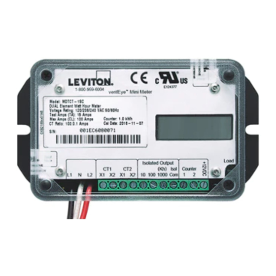
Connection Summary - The power and terminal block connections are identified as follows
(from left to right):
L1
Power, Line 1 (black)
N
Neutral (white)
L2
Power, Line 2 (red) (used for dual element meters only)
CT1 - X1
Current transformer input, black (or colored) wire of CT1
CT1 - X2
Current transformer input, white wire of CT1
CT2 - X1
Current transformer input, red (or colored) wire of CT2 (used for dual element meters only)
CT2 - X2
Current transformer input, white wire of CT2 (used for dual element meters only)
Output - 10
Total Real Energy (kWh) consumption (energy delivered) pulse output, plus (+) connection.
10Wh pulse rate (5 watt hours on, 5 watt hours off)
Output - 100
Total Real Energy (kWh) consumption (energy delivered) pulse output, plus (+) connection.
100Wh pulse rate (50 watt hours on, 50 watt hours off)
Output - 1000 (Kh)
Total Real Energy (kWh) consumption (energy delivered) pulse output, plus (+) connection.
1kWh pulse rate (500 watt hours on, 500 watt hours off)
Output - Isol Com
Common (-) connection for 10 Wh, 100 Wh and 1000 Wh Isolated Pulse Outputs.
Counter 1
For 12 VDC electro-mechanical counter, no polarity (not isolated).
Counter 2
For 12 VDC electro-mechanical counter, no polarity (not isolated).
+12VDC
12 VDC @ 10 mA output (not isolated) for specialized applications such as a line powered
transmitter. Use with COUNTER (2).
For complete installation instructions specific to the meter being installed, please refer to the
Mini Meters Installation and User's Manual at www.leviton.com.
FOR CANADA ONLY
For warranty information and/or product returns, residents of Canada should contact Leviton in writing at
Leviton Manufacturing of Canada Ltd to the attention of the Quality Assurance Department, 165 Hymus
Blvd, Pointe-Claire (Quebec), Canada H9R 1E9 or by telephone at 1 800 405-5320.
LIMITED 5 YEAR WARRANTY AND EXCLUSIONS
Leviton warrants to the original consumer purchaser and not for the benefit of anyone else that this product at the time of
its sale by Leviton is free of defects in materials and workmanship under normal and proper use for five years from the
purchase date. Leviton's only obligation is to correct such defects by repair or replacement, at its option. For details visit
www.leviton.com or call 1-800-824-3005. This warranty excludes and there is disclaimed liability for labor for removal
of this product or reinstallation. This warranty is void if this product is installed improperly or in an improper environment,
overloaded, misused, opened, abused, or altered in any manner, or is not used under normal operating conditions or not in
accordance with any labels or instructions. There are no other or implied warranties of any kind, including merchantability
and fitness for a particular purpose, but if any implied warranty is required by the applicable jurisdiction, the duration of
any such implied warranty, including merchantability and fitness for a particular purpose, is limited to five years. Leviton is
not liable for incidental, indirect, special, or consequential damages, including without limitation, damage to,
or loss of use of, any equipment, lost sales or profits or delay or failure to perform this warranty obligation. The
remedies provided herein are the exclusive remedies under this warranty, whether based on contract, tort or otherwise.
For Technical Assistance Call: 1-800-824-3005 - www.leviton.com
AVERTISSEMENT
• AVERTISSEMENT : POUR ÉVITER LES RISQUES D'INCENDIE, DE DÉCHARGE ÉLECTRIQUE OU
D'ÉLECTROCUTION, couper toutes les sources d'alimentation des produits à installer avant de procéder à leur câblage.
• Se servir d'un détecteur de tension aux valeurs nominales appropriées pour s'assurer que le courant a bien été coupé.
• L'installation de compteurs électriques implique une exposition à des tensions possiblement dangereuses.
• Les présentes directives sont conçues en guise de supplément pour aider des professionnels formés et qualifiés.
• L'installation doit être effectuée conformément à tous codes locaux et nationaux de l'électricité.
• Pour qu'ils puissent offrir les protections indiquées, les produits décrits doivent être utilisés conformément aux
présentes directives.
60 Hz
Plage de tensions d'alimentation
108-132 V c.a.
(ligne à neutre)
Puissance d'entrée maximale
5 VA max.
Fréquence de ligne
60 Hz
Courant nominal maximal
Primaire : courant nominal + 10 %
(100/200 A/m)
Secondaire : 110 mA (0,11 A)
0,5 à 1,0 (facteur inductif)
Plage de facteurs de puissance
0,866 à 1,0 (facteur capacitif)
Conforme à la norme ANSI C12.20 (0,5 %) en présence de
Précision (de -20 à 50 °C)
transformateurs de courant à noyau monobloc de Leviton (sortie
maximale de 100 mA) Résistance de charge des compteurs à 3 Ω.
Température de fonctionnement
-30 à 70 °C
et de rangement
Specifications
60 Hz
50 Hz
108 - 132 VAC
216 - 264 VAC
5 VA Max.
16 VA Max.
60 Hz
50 Hz
Primary: Max Rated Current +10%
Secondary: 110mA (0.11A)
0.5 lagging to 1.0
0.866 leading to 1.0
Meets ANSI C12.20 (class 0.5%) with Leviton Solid Core CT's with 100
mA max output. Meter input burden resistance at 3 Ohms.
-30°C to 70°C
Fiche technique
50 Hz
216-264 V c.a.
16 VA max.
50 Hz
Mini Meters
OEM Module
4.620
2.150
3.525
5.130
5.130
.125
Series
M = OEM Module
Single/Dual Element
S = Single Element
D = Dual Element
Output
NC = Counter resolution 0.1 kWh
TC = Counter resolution 1 kWh
Option of Terminal
T = Normal Terminal
INSTALLATION GUIDELINES
Observe the following guidelines when installing current transformers and connecting them to a meter:
• For installation, power must be de-energized and the circuit opened in order to slip the CT over the power line.
• To reduce the risk of electric shock, always open or disconnect circuit from power-distribution system
(or service) of building before installing or servicing current transformers.
• The current transformers may not be installed in equipment where they exceed 75 percent of the wiring space
of any cross-sectional area within the equipment.
• Installation is intended for Overvoltage Category IV or Service Entrance.
• DO NOT install a current transformer in an area where it would block ventilation openings.
• DO NOT install a current transformer in area of breaker arc venting.
• Current transformers are not suitable for Class 2 wiring methods and are not intended for connection to
Class 2 equipment.
• Secure current transformer and route conductors so that they do not directly contact live terminals or bus.
• Current transformer lead lengths may be extended up to 500 feet, although doing so may adversely affect the
accuracy of meter readings. When extending lead lengths, use twisted wires matching the gauge of the CT's
attached leads and follow NEC and local electrical codes.
100:0.1A CTs
Primary: 100A
Secondary: 110mA (0.11A)
200:0.1A CTs
Primary: 200A
Secondary: 110mA (0.11A)
Pollution Degree 2
Normally only non-conductive pollution occurs. Occasionally, however, a temporary
conductivity caused by condensation must be expected.
A
B
C
CT Size
100:0.1A
200:0.1A
Minicompteurs
Modules de fabricant
4.620
2.150
3.525
5.130
5.130
.125
Gamme
M = Module de fabricant
Single/Dual Element
S = Un élément
D = Deux éléments
Output
NC = Résolution de mesure de 0,1 kWh
TC = Résolution de mesure de 1 kWh
Type de bornes
T = Bornes normales
2.150
Dimensions (inches)
2.845
.125
1.107 1.282
Model Number Key
M X XX T – X XX
CT Type
SC = Solid Core
SP = Split Core
NC = No CTs
Amperage Rating
1 = 100A
2 = 200A
Maximum Rated Current
A
B
X1
C
X2
D
A
B
H1
0.72"
2.06"
(18.3mm)
(52.3mm)
2.150
Dimensions (po)
2.845
.125
Model Number Key
1.107 1.282
M X XX T – X XX
Type de TC
SC = À noyau monobloc
SP = À noyau ouvrant
NC = Aucun TC
Intensité nominale
1 = 100 A
2 = 200 A
PK-A3233-10-02-0A-X2
4.620
ENGLISH
2.845
3.525
5.130
1.107 1.282
5.130
X1
X2
D
H1
C
D
0.82"
48.00"
(20.8mm)
(1219mm)
4.620
FRANÇAIS
2.845
3.525
5.130
1.107 1.282
5.130
Publicidad

Manuales relacionados para Leviton Mini Meters


Resumen de contenidos para Leviton Mini Meters
- Página 1 LIMITED 5 YEAR WARRANTY AND EXCLUSIONS Leviton warrants to the original consumer purchaser and not for the benefit of anyone else that this product at the time of its sale by Leviton is free of defects in materials and workmanship under normal and proper use for five years from the purchase date.
- Página 2 Leviton garantit au premier acheteur, et uniquement au crédit du dit acheteur, que ce produit ne présente ni défauts de fabrication ni défauts de matériaux au moment de sa vente par Leviton, et n’en présentera pas tant qu’il est utilisé de façon normale et adéquate, pendant une période de 5 ans suivant la date d’achat.