Tabla de contenido
Publicidad
Idiomas disponibles
Idiomas disponibles
Enlaces rápidos
I
CENTRALE DIGITALE PER IL COMANDO DI UN MOTORE TRIFASE
GB
DIGITAL CONTROL UNIT TO CONTROL A THREE PHASE MOTOR
F
ARMOIRE DE COMMANDE NUMÉRIQUE D'UN MOTEUR TRIPHASÉ
D
DIGITALE STEUERUNG ZUM STEUERN EINES DREIPHASENMOTORS
E
CUADRO DE MANIOBRAS DIGITAL PARA EL MANDO DE UN MOTOR TRIFÁSICO
KEY AUTOMATION S.R.L.
Via S. Urbano, 7 - 31010 Pianzano di Godega S.Urbano (TV) ITALY
tel. +39 - 0421 307456
fax +39 - 0421 65698
info@keyautomation.it
www.keyautomation.it
900CT-380
900CT-381
IL n.228-K
EDIZ. 12/09/2006
(Pr. 1.0)
Publicidad
Capítulos
Tabla de contenido

Manuales relacionados para Key Automation 900CT-380


Resumen de contenidos para Key Automation 900CT-380
- Página 1 KEY AUTOMATION S.R.L. Via S. Urbano, 7 - 31010 Pianzano di Godega S.Urbano (TV) ITALY tel. +39 - 0421 307456 fax +39 - 0421 65698 IL n.228-K info@keyautomation.it www.keyautomation.it EDIZ. 12/09/2006 900CT-380 900CT-381 (Pr. 1.0) CENTRALE DIGITALE PER IL COMANDO DI UN MOTORE TRIFASE DIGITAL CONTROL UNIT TO CONTROL A THREE PHASE MOTOR ARMOIRE DE COMMANDE NUMÉRIQUE D'UN MOTEUR TRIPHASÉ...
- Página 3 ISTRUZIONI ..........1 INSTRUCTIONS .
-
Página 5: Tabla De Contenido
TABELLA FUNZIONI 900CT-380 ........ -
Página 6: Avvertenze Importanti
• Per la connessione di tubi rigidi e flessibili o passacavi La 900CT-380 è dotata di un display il quale permette, oltre utilizzare raccordi conformi al grado di protezione IP55 o che una facile programmazione, il costante monitoraggio dello superiore. -
Página 7: Installazione
ATTENZIONE: la centrale non fornisce nessuna protezione sui motori. Si consiglia di installare un dispositivo salvamotore prima del motore. LAMPEGGIATORE La centrale 900CT-380 prevede l’utilizzo di un lampeggiatore a 230V 40W con intermittenza interna. Collegare i cavi del lampeggiante ai morsetti B1 e B2 della centrale. -
Página 8: Coste Sensibili
P13 e P14 della centrale. centralina tra i morsetti P13 e P14 della 900CT-380. In caso • Collegare i cavi di alimentazione dei ricevitori delle contrario collegarli tra i morsetti P12 e P14. -
Página 9: Stop
Se il led è acceso il contatto è chiuso, se è spento il contatto RICEVITORE AD INNESTO è aperto. La centrale 900CT-380 è predisposta per l'innesto di un ricevitore della serie 900RXI-44 con architettura super- eterodina ad elevata sensibilità. ATTENZIONE: Prima di eseguire le seguenti operazioni disalimentare la centrale di comando. -
Página 10: Pannelo Di Controllo
PANNELLO DI CONTROLLO USO DEI TASTI DOWN MENU E UP PER LA Quando viene attivata l'alimentazione, la centrale verifica il PROGRAMMAZIONE corretto funzionamento del display accendendo tutti i segmenti La programmazione delle funzioni e dei tempi della centrale per 1,5 sec. 8.8.8.8. Nei successivi 1,5 sec. viene visualizzata viene fatta in un apposito menu di configurazione a cui si la versione del firmware, ad esempio Pr I.0. -
Página 11: Configurazione Veloce
In entrambi i casi per rendere attiva la nuova configurazione è indispensabile eseguire la corretta procedura di uscita tramite la voce FinE. La centrale 900CT-380 dispone di una procedura di autoapprendimento dei tempi di lavoro; è consigliabile perciò impostare inizialmente una configurazione standard (paragrafo precedente), eseguire l’autoapprendimento, e in seguito... - Página 12 CARICAMENTO DEI PARAMETRI DI DEFAULT 3. Mentre è visualizzata la revisione del firmware, premere il tasto UP: la centrale visualizza un conto alla rovescia (da In caso di necessità, è possibile riportare tutti i parametri al dE.-9 a dE-1). loro valore standard o di default (vedere la tabella riassuntiva 4.
- Página 13 Tempo prelampeggio Prima di ogni movimento del cancello, il lampeggiatore viene attivato per il tempo t.PrE, per segnalare l’imminente manovra. Start in apertura Questo menù permette di stabilire il comportamento della centrale se viene ricevuto un comando di Start durante la fase di apertura. PAUS Il cancello si ferma ed entra in pausa ChiU...
- Página 14 Start pedonale in apertura parziale Questo menù permette di stabilire il comportamento della centrale se viene ricevuto un comando di Start Pedonale durante la fase di apertura parziale. PAUS Il cancello si ferma ed entra in pausa ChiU Il cancello inizia immediatamente a richiudersi Il cancello continua ad aprirsi (il comando viene ignorato) ATTENZIONE: Un comando di Start ricevuto in qualunque fase dell’apertura parziale provoca un’apertura totale;...
-
Página 15: Ingresso Stop
Funzione degli ingressi di Start Questo menù permette di scegliere la modalità di funzionamento degli ingressi (vedere paragrafo Ingressi di Attivazione): StAn Funzionamento standard degli ingressi di Start e Start Pedonale, secondo le impostazioni dei menu. Gli ingressi di Start da morsettiera sono disabilitati. Gli ingressi radio funzionano secondo la modalità... - Página 16 Ingresso foto 2 Questo menù permette di abilitare l’ingresso per le fotocellule di tipo 2, cioè non attive in apertura (vedere il paragrafo installazione). Ingresso disabilitato (la centrale lo ignora). Non è necessario ponticellare con il comune. CF.CH Ingresso abilitato anche a cancello fermo: la manovra di apertura non inizia se la fotocellula è...
- Página 17 Ingresso Finecorsa La centrale 900CT-380 permette il collegamento di finecorsa meccanici (contatto normalmente chiuso) che vengono attivati dal movimento delcancello e indicano alla centrale la posizione di completa apertura o chiusura. Ingressi disabilitati (la centrale li ignora). Non è necessario ponticellare con il comune.
-
Página 18: Lettura Del Contatore Di Cicli
I DATI IMPOSTATI SONO STATI SALVATI IN MEMORIA: LA CENTRALE È ORA PRONTA PER L'UTILIZZO. LETTURA DEL CONTATORE DI CICLI La centrale 900CT-380 tiene il conto dei cicli di apertura del cancello completati e, se richiesto, segnala la necessità di manutenzione dopo un numero prefissato di manovre. -
Página 19: Anomalie Di Funzionamento
ANOMALIE DI FUNZIONAMENTO Errore 5 Quando viene dato un comando di start il cancello non si apre In questo paragrafo vengono elencate alcune anomalie di e sul display appare la scritta: funzionamento che si possono presentare, ne viene indicata la causa e la procedura per porvi rimedio. -
Página 20: Tabella Funzioni 900Ct-380
TABELLA FUNZIONI 900CT-380 MEMO DISPLAY DATI DESCRIZIONI DEFAULT DATI t.AP 0.0" ÷ 2.0' Tempo apertura 15.0" t.APP 0.0" ÷ t.AP1 Tempo apertura pedonale 6.0" t.Ch 0.0" ÷ 2.0' Tempo chiusura 16.0" t.ChP 0.0" ÷ t.Ch Tempo chiusura pedonale 7.0" t.PrE 0.5"... - Página 21 TABELLA FUNZIONI 900CT-380 MEMO DISPLAY DATI DESCRIZIONI DEFAULT DATI Fot 1 Ingresso FOTO 1. APCh - Funziona come fotocellula attiva in apertura e in chiusura. - Disabilitato. Fot 2 Ingresso FOTO 2. CFCh CFCh - Funziona come fotocellula attiva in chiusura e con cancello fermo.
-
Página 22: Tabella Collegamenti Elettrici
TABELLA COLLEGAMENTI ELETTRICI Schermatura antenna W1 - W2 - Motore (vedi paragrafo ALIMENTAZIONE E MOTORI) Centrale antenna Morsetti per collegare la terra del motore alla Comando di apertura per il collegamento di W4 - W5 terra dell’impianto dispositivi tradizionali con contatto N.A. B1 - B2 Lampeggiante 230VAC 40W Comando di apertura pedonale per il collegamento... - Página 23 900CT-380 FUNCTION TABLE ........
-
Página 24: Important Remarks
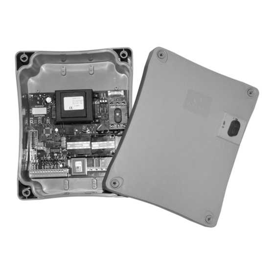
DESCRIZIONE DELLA CENTRALE • After making connections on the terminal board, use one The control unit 900CT-380 is an innovative KEY product that hose clamp to fix dangerous voltage wires near the terminal guarantees a safe and reliable automation of industrial sliding board and another hose clamp to fix safety low voltage wires gates and multi-section doors. -
Página 25: Installation
IMPORTANT: the control unit provides no protection to the motors. A motor protection device should be installed before the motor. BLINKER 900CT-380 control unit provides for a 230V 40W blinker equipped with intermittence inside. Connect blinker cables to terminals B1 and B2 of the control unit. -
Página 26: Safety Ribbons
P9 of the control unit. 900CT-380 control unit supplies a 24VAC power supply to In order to meet standard EN12978 requirements, edges must photocells and it can perform a photocell operation test before be installed that are sensitive to conductive rubber;... -
Página 27: Stop
Pay attention to the way you connect the removable modules. 900RXI-44 module receiver is provided with 4 channels and each of them is suitable for a command of 900CT-380 control unit: ACTIVATION INPUTS CHANNEL 1... -
Página 28: Control Panel
CONTROL PANEL USE OF DOWN MENU AND UP KEYS FOR When power is on, the control unit checks that display correctly PROGRAMMING operates by switching on all segments for 1.5 sec. 8.8.8.8. Control unit time and function programming is made within a Firmware version, e.g. -
Página 29: Quick Configuration
As for both cases, you will have to perform the right exit procedure through item FinE, in order to activate your new configuration. 900CT-380 control unit provides for a self-learning procedure of working times; therefore, we recommend that you set up a standard configuration first (see previous paragraph), then you carry out the self-learning and finally you change any unsatisfactory items. -
Página 30: Loading Of Default Parameters
LOADING OF DEFAULT PARAMETERS 4. Before the end of the countdown, press the key MENU: all the parameters are rescribed with their default value and If necessary, it is possible to restore all the parameters to their the configuration menu is started, in order to make the standard or default value (see table at the end). - Página 31 Pre-blinking time Before any gate movement, blinker will be activated for t.PrE time, to warn about the incoming motion. Start command during the opening phase This menu allows fixing the control unit conduct in case it receives a Start command during the opening phase. PAUSThe gate stops and goes to pause ChiU The gate immediately starts closing...
- Página 32 Pedestrian Start during the partial opening phase This menu allows fixing the control unit conduct in case it receives a Pedestrian Start command during the partial opening phase. PAUSThe gate stops and goes to pause ChiU the gate immediately starts closing the gate goes on with the opening phase (command is ignored) WARNING: a Start command in any phase of partial opening will cause...
-
Página 33: Stop Input
Start input function This menu allows selecting input operation modes (see paragraph “Activation inputs”): StAn Start and Pedestrian Start input standard operation, according to menu setups. Start inputs from terminal board are disabled. Radio inputs operate in StAn mode. AP.CH Start impulse always controls the opening phase, Pedestrian Start always controls the closing phase. - Página 34 Photocell 2 input This menu allows enabling the input for type 2 photocells, that is to say, photocells non active during the opening phase (see paragraph “Installation”). input disabled (ignored by the control unit). No jumper with the common is required. CF.CH input enabled even at standstill gate too: the opening movement does not start if photocell is interrupted.
- Página 35 End of Stroke Inputs 900CT-380 control unit allows connecting mechanical ends of stroke (normally closed contacts) which are activated by the gate motion and showing to the control unit the position of complete opening or closing. End of stroke inputs are disabled.
-
Página 36: Reading Of Cycle Counter
THE INSERTED DATA HAVE BEEN MEMORIZED: THE CONTROL UNIT IS READY TO BE USED. READING OF CYCLE COUNTER 900CT-380 control unit counts the completed opening cycles of the gate and, if requested, it shows that service is required after a fixed number of cycles. -
Página 37: Operation Defects
MAINS led does not switch on It means that there is no voltage on 900CT-380 control unit card. 1. Make sure there is no voltage interruption at the power unit It means that the safety edge test failed (if using conductive source and that the switch is turned to ON. -
Página 38: 900Ct-380 Function Table
900CT-380 FUNCTION TABLE MEMO DISPLAY DATA DESCRIPTION DEFAULT DATA t.AP 0.0" ÷ 2.0' Gate opening time 15.0" t.APP 0.0" ÷ t.AP1 Opening time of pedestrian gate 6.0" t.Ch 0.0" ÷ 2.0' Gate closing time 16.0" t.ChP 0.0" ÷ t.Ch Closing time of pedestrian gate 7.0"... - Página 39 900CT-380 FUNCTION TABLE MEMO DISPLAY DATA DESCRIPTION DEFAULT DATA Fot 1 PHOTO 1 input APCh - Input is available for the connection of the photocell - Not available Fot 2 PHOTO 2 input CFCh CFCh - Photocell is active in closing and also when the gate is still...
-
Página 40: Electric Connections Table
TABELLA COLLEGAMENTI ELETTRICI Antenna shield W1 - W2 - Motor (see paragraph POWER SUPPLY AND MOTORS) Antenna Clamps to connect the motor's earth system to Opening control for the connection of control W4 - W5 the plant's earth system devices with N.O. contact B1 - B2 Flashing light 230VAC 40W Opening controls for pedestrian access for the... - Página 41 TABLEAU FONCTIONS 900CT-380 ........
-
Página 42: Conseils Importants
à tension qui se industrielles. trouvent en proximité de la borniere et sur les conducteurs La conception de projet de la 900CT-380 a visé réalisation pour le branchement des parties externes (accessoires). d'un produit qui soit en mesure de correspondre à toutes les De cette maniere, en cas de détachement d'un conducteur,... -
Página 43: Installation
Il est conseillé d'installer un discontacteur avant du moteur. CLIGNOTANT L’armoire 900CT-380 prévoit l’emploi d’un clignotant à 230V - 40W avec intermittence interne. Brancher les câbles du clignotant aux bornes B1 et B2 de l’armoire. Triphasée 230V (par rapport au schéma précédent seulement la liaison de sélection de la tension change) -
Página 44: Barres Palpeuses
P13 entre les bornes P4 et P5 de la centrale et la sortie des et P14 de la 900CT-380. Dans le cas contraire, connecter-les récepteurs des cellules de type 2 entre les bornes P4 et P6 entre les bornes P12 et P14. -
Página 45: Stop
à la centrale de commande. Faire bien attention au vers de branchement des modules extraibles. Le module récepteur 900RXI-44 est doué de 4 canaux. A chacun on a associé un commande de l'armoire 900CT-380: ENTREES DE ACTIVATION • CANAL 1 START L’armoire 900CT-380 est douée de deux entrée d’activation,... -
Página 46: Panneau De Controle
PANNEAU DE CONTROLE EMPLI DES TOUCHES DOWN ET UP POUR LA Quand on active l’alimentation, l’armoire vérifie le correct PROGRAMMATION fonctionnement de l’écran, en allumant tous les segments pour La programmation des fonctions et des temps de l’armoire est 1,5 sec. 8.8.8.8. Dans les 1,5 sec. suivants, vient visualisée la faite dans un menu propre de configuration au quel on peut version du logiciel, pour exemple Pr I.0. -
Página 47: Configuration Rapide
Dans ce paragraphe viens illustre pas-pas la procédure pour la configuration de tous les paramètres de fonctionnement de l’armoire 900CT-380. Il est possible faire une configuration complète de l’armoire, suivant tout pas la procédure, ou sélectionner seulement les voix qu’intéressent. En tout cas, pour rendre active la nouvelle configuration est indispensable exécuter la procédure correcte de sortie à... -
Página 48: Chargement Des Parametres Implicites
CHARGEMENT DES PARAMETRES IMPLICITES 3. Pendant que l'affichage montre la révision du firmware, presser la touche UP : l'armoire visualise un compte à En cas de besoin, il est possible de remettre tous les rebours (de dE.-9 à dE-1). paramètres à leur valeur standard ou implicite (voir tableau 4. -
Página 49: Start En Ouverture
Temps clignotement préalable Avant de chaque mouvement du portail, le clignotant viens activé pour le temps t.PrE, pour signaler que commence le mouvement. Start en ouverture Ce menu permet d’établir le comportement de l’armoire s’il reçoit un commande de Start pendant la phase d’ouverture. PAUS Le portail s’arrête et entre en pause. - Página 50 Start piétonne en ouverture partielle Ce menu permet d’établir le comportement de l’armoire s’il reçoit un commande de Start Piétonne pendant la phase d’ouverture partielle. PAUS Le portail s’arrete et entre en pause. ChiU Le portail commence à se refermer. Le portail continue à...
- Página 51 Fonction des entrées de Start Ce menu permet de choisir le mode de fonctionnement des entrées (voir paragraphe entrées de Activation) StAn Fonctionnement standard des entrées de Start et Start Piétonne, selon les postages des menus. Les entrées de Start sur la borniere sont des-habilitées. Les entrées fonctionnent selon le mode StAn.
-
Página 52: Test Des Dispositifs De Sécurité
Entrée photo 2 Ce menu permet de habiliter l’entrée pour les photocellules de type 2, c’est à dire non-active en ouverture (voir le paragraphe installation). Entrée des-habilitée (l’armoire l’ignore). Il n’est pas nécessaire pointer avec le commun CF.CH Entrée habilitée aussi à portail fermé : l’ouverture ne commence pas si la photocellule est interrompue Entrée habilitée seulement en fermeture. -
Página 53: Entrées Butées De Fin De Course
Entrées butées de fin de course La centrale 900CT-380 permet le branchement de butées de fin de courses mécaniques (contact normalement fermé) qui sont activés par le mouvement des portails et ils indiquent à la centrale la position de complète ouverture ou fermeture. -
Página 54: Lecture Du Compteurs De Cycles
LES DONNEES PREREGLEES ONT ETE MEMORISEES: LA CENTRALE EST DESORMAIS PRETE POUR L'UTILISATION. LECTURE DU COMPTEURS DE CYCLES L’armoire 900CT-380 tiens le compte des cycles d’ouverture du portails complétés et si souhaité, signale la nécessite d’entretien après un nombre fixé de manœuvres. -
Página 55: Anomalie De Fonctionnement
ANOMALIE DE FONCTIONNEMENT Remplacer le capteur fin course ou la partie du câblage endommagé. Si l'erreur persiste, envoyer l'armoire à KEY pour En ce paragraphe sont énumérées aucunes anomalies de la réparation. fonctionnement qu’on se puissent présenter; on indique la cause et la procédure pour les résoudre. -
Página 56: Tableau Fonctions 900Ct-380
TABLEAU FONCTIONS 900CT-380 MEMO DISPLAY DONNES DESCRIPTION DEFAULT DONNES t.AP 0.0" ÷ 2.0' Durée ouverture portail 15.0" t.APP 0.0" ÷ t.AP1 Durée ouverture portail piéton 6.0" t.Ch 0.0" ÷ 2.0' Durée fermeture portail 16.0" t.ChP 0.0" ÷ t.Ch Durée fermeture portail piéton 7.0"... - Página 57 TABLEAU FONCTIONS 900CT-380 MEMO DISPLAY DONNES DESCRIPTION DEFAULT DONNES Fot 1 Entrée photocellule 1 APCh - Fonctionne comme photocellule active en ouverture ou fermeture - Désactivé Fot 2 Entrée photocellule 2 CFCh CFCh - Fonctionne photocellule active en fermeture et avec portail arrêté...
-
Página 58: Tableau Branchements Electriques
TABLEAU BRANCHEMENTS ELECTRIQUES Blindage antenne W1 - W2 - Moteur (voir le paragraphe « ALIMENTATION ET MOTEURS ») Centrale antenne Bornes pour relier la mise à la terre du moteur à Commande d'ouverture pour le branchement de W4 - W5 la terre de l'installation commande traditionnels avec contact N.O. - Página 59 FUNKTIONSÜBERSICHT 900CT-380 ........
-
Página 60: Wichtige Hinweise
Sie sich an unser Kundendienst. Steuerung 900CT-380 mit der durch die EG-Richtlinie 93/68/EEC, 73/23/EEC, festgelegten wesentlichen Die Firma KEY Automation behält sich das Recht vor, das Erfordernissen. Für die Konformität-skontrolle wurden die Produkt ohne vorherige Ankündigungen abzuändern; die folgenden technischen Normen angewandt: Übernahme der Haftung für Schäden an Personen oder... -
Página 61: Installation
Motorenschutzvorrichtung geliefert. Es wird daher empfohlen, vor dem Motor eine Motorenschutzvorrichtung zu installieren. BLINKVORRICHTUNG In die Steuerung 900CT-380 ist eine Blinkeinrichtung mit interner Blinkschaltung mit 230V - 40W integriert. Kabel der Blinkeinrichtung bitte an die Klemmen B1 und B2 der Steuerung anschließen. -
Página 62: Empfindliche Rippen
Stromkabel der Steuerung zwischen den Klemmen • Ausgang der Empfänger der Fotozellen Typ 1 zwischen die P13 und P14 der 900CT-380 anzuschließen. Andernfalls werden Klemmen P4 und P5 der Steuerung und den Ausgang der diese zwischen den Klemmen P12 und P14 angeschlossen. -
Página 63: Stop
STOP-Eingangs an. Ein eingeschaltetes LED bedeutet, dass der Kontakt geschlossen, ein ausgeschaltetes, dass er offen ist. EINSTECKEMPFÄNGER Die Steuerung 900CT-380 ist zum Einstecken eines Empfängers der Serie 900RXI-44 mit einem hoch empfindlichen Superüberlagerungsempfängermodul ausgestattet. ACHTUNG: Vor den folgenden Operationen trennen Sie bitte die Steuerung vom Stromnetz. -
Página 64: Steuerpult
STEUERPULT VERWENDUNG DER TASTEN DOWN MENU Wenn der Strom eingeschaltet wird, prüft die Steuereinheit das UND UP ZUM PROGRAMMIEREN korrekte Funktionieren des Displays indem es alle Segmente Die Programmierung der Funktionen und Zeiten der Steuerung 1,5 sec. lang auf 8.8.8.8. schaltet. In den nachfolgenden 1,5 erfolgt in einem entsprechenden Konfigurationsmenü. -
Página 65: Schnellkonfiguration
Optionen von Interesse. In beiden Fällen ist es zum Aktivieren der neuen Konfiguration notwendig, die korrekte Prozedur des Verlassens mittels Option FinE durchzuführen. Die Steuerung 900CT-380 verfügt über eine Selbstlernprozedur der Arbeitszeiten; es ist daher ratsam, anfänglich eine Standardkonfiguration (vorhergehender Abschnitt zu nutzen), die Selbstlernprozedur durchzuführen. -
Página 66: Einstellung Der Standardparameter
EINSTELLUNG DER STANDARDPARAMETER 4. Drücken Sie die Taste MENU vor dem Ende des Herunterzählens: alle Parameter werden mit ihren Im Notfall ist es möglich alle Parameter mit ihrem Standardwert Standardwerten wieder eingestellt und das wieder einzustellen (sehen Sie die letzte Übersichttabelle). Konfigurationsmenu wird aktiviert, sodass man sofort die nötigen Änderungen machen kann. - Página 67 Vorabblinkzeit Vor jeder Torbewegung wird die Blinkvorrichtung über die Zeit t.PrE aktiviert, um eine kurz bevorstehende Bewegung anzukündigen. Start während dem Öffnen Diese Menüoption ermöglicht es, das Verhalten der Steuerung festzulegen, wenn während der Öffnungsphase ein Startbefehl erteilt wird. PAUS Das Tor stoppt und geht in Pausenstellung.
- Página 68 Start Fußgängerzugang (bei einseitiger / partieller Öffnung) Dieses Menü ermöglicht es, das Verhalten der Steuereinheit festzulegen, wenn ein Start-Pedonale-Befehl während der Phase der partiellen Öffnung empfangen wird. PAUS Das Tor stoppt und geht in Pause. ChiU Das Tor beginnt auf der Stelle sich wieder zu schließen. Das Tor öffnet sich weiter (der Befehl wird ignoriert).
-
Página 69: Eingang Stop
Funktion der Start-Eingänge Diese Menüoption ermöglicht es, den Funktionsmodus der Eingänge zu wählen (siehe Abschnitt Aktivierungseingänge): StAn Standardfunktion der Start- und Start Fußgänger-Eingänge entsprechend den Menüeinstellungen. Die Starteingänge vom Klemmnbrett sind deaktiviert. Die Funkeingänge funktionieren im Modus StAn. AP.CH Der Start-Impuls aktiviert stets das Öffnen, der Start Fußgänger-Impuls aktiviert stets das Schließen. - Página 70 Eingang Foto 2 Diese Menüoption ermöglicht es, den Eingang für die Fotozellen Typ 2 zu aktivieren, die beim Öffnen und Schließen nicht aktiv sind (siehe Abschnitt Installation). Eingang deaktiviert (die Steuerung ignoriert diesen). Es ist keine Überbrückung mit dem Gemeinsamen notwendig. CF.CH Eingang auch bei stehendem Tor aktiv: das Öffnungsmanöver beginnt nicht, wenn die Fotozelle unterbrochen ist.
- Página 71 Eingänge Endanschläge Die Steuerung 900CT-380 gestattet den Anschluss von zwei mechanischen Endanschlägen (NC-Kontakt), welche durch die Torbewegung aktiviert werden und der Steuerung die völlige Öffnung oder die völlige Schließung melden. Die Eingänge der Endanschläge sind inaktiv. Die Eingänge der Endanschläge sind aktiv.
-
Página 72: Ablesen Des Zykluszählers
Änderungen abgeschlossen: Ende Programmierung. DIE EINSTELLUNGEN WERDEN GESPEICHERT: DIE STEUERUNG IST BETRIEBSBEREIT ABLESEN DES ZYKLUSZÄHLERS Die Steuerung 900CT-380 zählt die vollständig ausgeführten Öffnungszyklen des Tores und zeigt nach einer voreingestellten Torbewegungsanzahl (Bewegungszyklen) die Notwen-digkeit einer Wartung an. Zwei Zähler sind verfügbar: •... -
Página 73: Funktionsstörungen
Ursache und die mögliche Behebung beschrieben. Die LED MAINS schaltet sich nicht ein Dies bedeutet, dass an der Leiterplatte der Steuerung 900CT-380 keine Stromversorgung anliegt. 1. Man stelle sicher, dass keine Spannungsunterbrechung an Dass heißt denn des Entschalter oder des Verbindungskabel einer der Steuerung vorgeschalteten Stelle erfolgt und (Sensor / Steuerung) ist defekt. -
Página 74: Beschreibung
FUNKTIONSÜBERSICHT 900CT-380 MEMO DISPLAY DATEN BESCHREIBUNG DEFAULT DATEN t.AP 0.0" ÷ 2.0' Öffnungszeit 15.0" t.APP 0.0" ÷ t.AP1 Zeit für partielle Öffnung (Fußgängerzugang) 6.0" t.Ch 0.0" ÷ 2.0' Schließzeit 16.0" t.ChP 0.0" ÷ t.Ch Zeit für partielles Schließen (Fußgängerzugang) 7.0"... - Página 75 FUNKTIONSÜBERSICHT 900CT-380 MEMO DISPLAY DATEN BESCHREIBUNG DEFAULT DATEN Fot 1 Eingang FOTO 1 APCh - Eingang aktiviert - Eingang deaktiviert (die Steuerung ignoriert diesen) Fot 2 Eingang FOTO 2 CFCh CFCh - Eingang auch bei stehendem Tor aktiv - Eingang deaktiviert (die Steuerung ignoriert diesen) - Eingang nur beim Schließen aktiviert...
-
Página 76: Elektrischäsverbindungstabelle
ELEKTRISCHÄSVERBINDUNGSTABELLE Steuerung Antenne W1 - W2 - Motor (lesen Sie den Paragraph STROMVERSORGUNG DER MOTOREN) Entstörung Antenne Klemmen für den Erdungsanschluss des Motors Öffnungsbefehl für die Anschlüsse der traditioneller W4 - W5 an die Erdung der Anlage Steuervorrichtungen mit NO-kontakt B1 - B2 Blinkvorrichtung 230VAC 40W Öffnungsbefehl Fußgängerdur-chgang für die... - Página 77 ÌNDICE ADVERTENCIAS IMPORTANTES .............74 CONFORMIDAD A LAS NORMATIVAS .
-
Página 78: Advertencias Importantes
De esta forma, La proyectación del 900CT-380 se ha dirigido a la realización se evita, en el caso de una desconexión accidental de un de un producto que se adapta a todas las exigencias, cable, que las partes con tensión de red entren en contacto... -
Página 79: Instalacion
Se recomienda instalar un dispositivo de protección a sobrecargas antes del motor. LAMPARA DE SEÑALIZACION El cuadro 900CT-380 prevé la utilización de una lámpara de señalización a 230V 40W con intermitencia interna. Conectar los cables de la lámpara de señalización entre los bornes B1 y B2 del cuadro. -
Página 80: Bandas De Seguridad
• Conectar los cables de alimentación de los receptores de cuardo entre los bornes P13 y P14 de la 900CT-380. En caso las fotocélulas entre los bornes P12 y P14 del cuadro. -
Página 81: Stop
Tener cuidado con el sentido de conexión del módulo receptor extraible. El modulo receptor 900RXI-44 dispone de 4 canales. Cada uno es asociado a un comando de la central 900CT-380. CANAL 1 START ENTRADAS DE ACTIVACION DEL CUADRO... -
Página 82: Panel De Control
PANEL DE CONTROL UTILIZACION DE LAS TECLAS DOWN, MENU Y Cuando se activa la alimentación, el cuadro verifica el correcto UP PARA LA PROGRAMACION funcionamiento del display encendiendo todos los segmentos La programación de las funciones y de los tiempos del cuadro durante 1,5 seg. -
Página 83: Configuracion Rapida
En ambos casos para que la nueva configuración quede programada es indispensable seguir el procedimiento correcto de salida mediante la voz FinE. El cuadro 900CT-380 dispone de un procedimiento de autoaprendizaje de los tiempos de trabajo; se aconseja, por lo tanto, programar inicialmente una configuración estándar (párrafo anterior), ejecutar el autoaprendizaje, y posteriormente... -
Página 84: Configuración Parámetros De Default
CONFIGURACIÓN PARÁMETROS DE DEFAULT 4. Antes de que la cuenta atrás termine, pulsar la tecla MENU: todos los parámetros son rescritos con su valor de default Si necesario, es posible devolver todos los parámetros a su y el menu de configuración es lanzado, para poder efectuar valores estándar o de default (ver tabla recapitulavia final) todas las modificaciones necesarias. -
Página 85: Tiempo De Predestello
Tiempo de predestello Antes de cada movimiento de la puerta, la lámpara de señalización se activa por el tiempo t.PrE, para indicar una maniobra inminente. Start en apertura Este menú permite establecer el comportamiento del cuadro si se recibe un comando de Start durante la fase de apertura. - Página 86 Start peatonal en apertura parcial Este menú permite establecer el comportamiento del cuadro si se recibe un comando de Start Peatonal durante la fase de apertura parcial. PAUS La puerta se para y entra en pausa ChiU La puerta se vuelve a cerrar inmediatamente La puerta continua a abrirse (el comando no viene sentido) ATENCION: Un comando de Start recibido en cualquier fase de la apertura parcial provoca una apertura total;...
-
Página 87: Funcionamiento De Las Entradas De Start
Funcionamiento de las entradas de Start Este menú permite elegir la modalidad de funcionamiento de las entradas (ver párrafo Entradas de Activación): StAn Funcionamiento estándar de las entradas de Start y Start Peatonal, según las programaciones de los menús. Las entradas de Start en los bornes están deshabilitados. Las entradas radio funcionan según la modalidad StAn. -
Página 88: Test De Los Dispositivos De Seguridad
Entrada foto 2 Este menú permite habilitare la entrada para las fotocélulas de tipo 2, activas en apertura (ver el párrafo instalación). Entrada deshabilitada (el cuadro la ignora). No es necesario puentear con el común. CF.CH Entrada habilitada incluso a puerta parada: la maniobra de apertura no empieza si la fotocélula está... -
Página 89: Entrada Finales De Carrera
Entrada finales de carrera El cuadro de maniobras 900CT-380 permite la conexión de finales de carrera mecánicos (contacto normalmente cerrado) que se activan con el movimiento de las puerta e indican al cuadro la posición de completa apertura o cierre. -
Página 90: Lectura Del Contador De Ciclos
CUADRO DE MANIOBRAS ESTÁ AHORA LISTO PARA SU UTILIZACIÓN. LECTURA DEL CONTADOR DE CICLOS El cuadro 900CT-380 cuenta los ciclos de apertura de la puerta completados y, si se quiere, señala la necesidad de mantenimiento después de un número establecido de maniobras. -
Página 91: Anomalias De Funcionamiento
El led MAINS no se enciende el display aparece la sigla: Significa que falta tensión a la placa del cuadro 900CT-380. 1. Asegúrese que no exista una interrupción de tensión hacia el cuadro y que el seccionador esté en ON. -
Página 92: Display Datos
TABLA DE FUNCIÓN 900CT-380 MEMO DISPLAY DATOS DESCRIPCIÓN DEFAULT DATOS t.AP 0.0" ÷ 2.0' Tiempo apertura puerta 15.0" t.APP 0.0" ÷ t.AP1 Tiempo apertura peatonal 6.0" t.Ch 0.0" ÷ 2.0' Tiempo cierre puerta 16.0" t.ChP 0.0" ÷ t.Ch Tiempo cierre peatonal 7.0"... - Página 93 TABLA DE FUNCIÓN 900CT-380 MEMO DISPLAY DATOS DESCRIPCIÓN DEFAULT DATOS Fot 1 Entrada FOTO 1 APCh - Funciona como fotocélula activa en apertura y en cierre - Deshabilitada Fot 2 Entrada FOTO 2 CFCh CFCh - Funciona como fotocélula activa en cierre y con la puerta parada - Deshabilitada - Funciona como fotocélula activa sólo en cierre...
-
Página 94: Tabla Conexiones Electricas
TABLA CONEXIONES ELECTRICAS Malla antena. W1 - W2 - Motor (ver párrafo ALIMENTACIÓN Y MOTORES) Positivo antena. Bornes para conectar la tierra del motor a la Comando de apertura para la conexión de W4 - W5 tierra del dispositivo dispositivos tradicionales de comando N.A. B1 - B2 Lámpara de señalización 230VAC 40W Comando de apertura peatonal para la conexión de... - Página 96 KEY AUTOMATION S.R.L. Via S. Urbano, 7 - 31010 Pianzano di Godega S.Urbano (TV) ITALY tel. +39 - 0421 307456 fax +39 - 0421 65698 info@keyautomation.it www.keyautomation.it...