Tabla de contenido
Publicidad
Idiomas disponibles
Idiomas disponibles
Enlaces rápidos
Publicidad
Tabla de contenido

Manuales relacionados para Steren K-810


Resumen de contenidos para Steren K-810
-
Página 2: Lo Que Se Debe Y No Se Debe Hacer Al Construir Circuitos
Únicamente conecte los circuitos integrados utilizando las confi guraciones ofrecidas en este libro, de otra forma se pueden dañar los componentes. Steren no se hace responsable por daños en piezas debido a un incorrecto ensamblaje. •... -
Página 3: Como Utilizar Las Piezas
• Nunca conecte el circuito a un contacto eléctrico • Nunca deje un circuito sin atender cuando esté encendido • Nunca toque el motor cuando esté rotando a alta velocidad ADVERTENCIA Peligro de choque eléctrico Nunca conecte los circuitos a contactos eléctricos en su hogar COMO UTILIZAR LAS PIEZAS Este kit de circuitos utiliza bloques de construcción que se conectan... - Página 4 Por ejemplo: Este es un interruptor el cual es verde y viene impreso un número en él. Este es un conector de circuitos azul y viene en diferentes tamaños y formas. Para construir cada proyecto requerirá una fuente de energía, dentro del paquete encontrará...
- Página 5 También se incluye una placa plástica para ayudar a mantener los bloques de circuitos unidos. No es necesario utilizar esta placa para construir proyectos, sin embargo ayuda a que los bloques se mantengan juntos. La bombilla de 2,5V viene separado del socket. Algunos circuitos utilizan cables de puenteo para realizar conexiones no usuales.
-
Página 6: Lista De Partes (Colores Y Estilos Pueden Variar)
LISTA DE PARTES (Colores y estilos pueden variar) Número Descripción Pieza 2 Cables suaves de conexión 2 Conectores de botón 6 conectores dobles 4 conectores triples 2 conectores con orificios 1 conector con orificios 2 conectores en escuadra 1 conector cuádruple 1 conector quíntuple 1 conector sextuple 2 conectores en zig zag... - Página 7 Número Descripción Pieza 1 placa sensitiva 1 Interruptor 1 Interruptor de presión 1 interruptor deslizable 1 fotosensor (CdS) 1 LED 1 lámpara de 2,5V 1 compartimiento de baterías 1 bocina ESPAÑOL-07...
- Página 8 Número Descripción Pieza 1 circuito musical 1 motor de CD 1 resistor 1 tubo de transmisión 1 tubo receptor 1 alarma 1 circuito de guerra del espacio 1 módulo de control 1 conector ESPAÑOL-08...
- Página 9 Número Descripción Pieza 1 ventilador amarillo 1 ventilador de colores 2 soportes de ruedas 2 ruedas 1 imán 1 LED parpadeante 1 LED parpadeante 6 sujetadores plásticos 1 foco ESPAÑOL-09...
-
Página 10: Experimentos
EXPERIMENTOS Coloque el interruptor en la posición de 3V 1.- Lámpara Cambie a la posición de encendido (ON) el switch 15, la lámpara 18 se encenderá. Apague el switch y la lámpara se apagará. 2.- Lámpara controlada manualmente Reemplace el interruptor 15 por el interruptor de presión 14. Presione el interruptor 14, y la lámpara se encenderá. - Página 11 Coloque el interruptor en la posición de 3V 4.- Ventilador eléctrico Arme el circuito que se muestra en la fi gura y asegúrese de que el interruptor deslizable 15 esté apagado en ese momento. Encienda el interruptor después de armar el circuito y el ventilador comenzará a girar.
- Página 12 Coloque el interruptor en la posición de 3V 10.- Altavoz Presione el interruptor 14, y la bocina 20 emitirá un sonido. ESPAÑOL-13...
- Página 13 Coloque el interruptor en la posición de 3V 11.- Lámpara y motor conectados en serie No conecte el ventilador amarillo en motor 24, encienda el interruptor 15, la lámpara 18 se encenderá y el motor girará (algunas veces será necesario rotar el pivote a mano) Apague el interruptor 15, el motor 24 detendrá...
- Página 14 Coloque el interruptor en la posición de 3V 12.- Lámpara y motor conectados en paralelo Encienda el interruptor 15, el ventilador comenzará a rotar y la lámpara se encenderá. Apague el switch 15 y el ventilador se detendrá y la lámpara se apagará. ESPAÑOL-15...
- Página 15 Coloque el interruptor en la posición de 3V 13.- LED Encienda el interruptor 15, el LED 17 se encenderá. Apague el interruptor y el LED se apagará. 14.- Directividad de LED Coloque el LED 17 de forma inversa y encienda el interruptor , el LED no se encenderá.
- Página 16 Coloque el interruptor en la posición de 3V 15.- LED y lámpara conectados en serie Encienda el interruptor 15, el LED 17 se encenderá pero no la lámpara. Esto es debido a que el LED necesita únicamente una pequeña cantidad de energía para encender y la lámpara necesita una mayor cantidad, en este circuito en serie solo se maneja una pequeña cantidad de energía.
- Página 17 Coloque el interruptor en la posición de 3V 17.- LED y motor conectados en serie Encienda el interruptor 15, el motor 24 no rotará pero el LED encenderá. 18.- LED y motor conectados en serie a la inversa Coloque el LED en forma inversa, encienda el interruptor 15, el motor y el LED no funcionarán.
- Página 18 19.- Lámpara y bocina conectados en serie Encienda el interruptor 15, la lámpara encenderá sutilmente. Coloque el interruptor en la posición de 3V Coloque el interruptor en la posición de 3V 20.- Lámpara y bocina conectados en paralelo Encienda el interruptor 15, la lámpara se encenderá y la bocina emitirá un sonido.
- Página 19 Coloque el interruptor en la posición de 3V 21.- Conexión serie-paralelo Encienda el interruptor 15, el motor comenzará a funcionar, y el LED y la lámpara se encenderán. Coloque el interruptor en la posición de 3V 22.- LED, motor y lámpara conectados en paralelo Opera como el proyecto anterior.
- Página 20 23.- Probador de conducción Con este probador de conducción puede identifi car que artículos de la vida diaria son conductores y cuáles no. Para hacer esto, únicamente necesita puentear el artículo a probar entre el punto A y el punto B. Si la lámpara se enciende, el artículo es conductor (puede ser un cuchillo o un recipiente de aluminio) Si la...
- Página 21 Coloque el interruptor en la posición de 3V 26.- Equipos electrónicos controlados respectivamente Arme el circuito de la fi gura. La lámpara 18 es controlada presionando el interruptor 14, y el motor es controlado por el interruptor deslizable. Los equipos electrónicos de la vida diaria como una lámpara, el televisor, refrigerador, etc.
- Página 22 Coloque el interruptor en la posición de 3V 27.- Encendido alternado de una lámpara y un LED controlados por imanes Cuando deslice el interruptor 15 hacia la posición de encendido, únicamente el LED se encenderá. Coloque un imán cerca del interruptor 13 y el LED se apagará...
- Página 23 30.- Encendido alternado de un motor y un LED controlados manualmente Reemplace la lámpara por el motor 24 y reemplace el interruptor 13 por el interruptor de presión 14, controle el circuito con el interruptor de presión 14, el LED 17 y el motor 24 trabajarán de forma alternada. Coloque el interruptor en la posición de 3V 31.- Lámpara de brillo variable controlada por un imán Encienda el interruptor 15, controle el interruptor 13 con un imán, el...
- Página 24 Coloque el interruptor en la posición de 3V 33.- Ventilador con velocidad variable controlado por imán Encienda el interruptor 15, controle el interruptor 14 con un imán, la velocidad del ventilador será variable. 34.- Ventilador de color con velocidad variable controlado por imán Reemplace el ventilador amarillo por el ventilador de color, la operación es la misma que en el proyecto anterior.
- Página 25 Coloque el interruptor en la posición de 6V 36.- Ventilador volador Coloque el ventilador amarillo en el motor, presione el interruptor 14, cuando el motor alcance la velocidad máxima, el ventilador saldrá volando por los aires (Nota: mantenga su cabeza fuera del camino!) Pregunta: Porque el ventilador amarillo sale volando por los aires? 37.- Rotación de un motor eléctrico en sentido de las manecillas del reloj y viceversa...
- Página 26 38.- Compuerta AND de una lámpara Encienda el interruptor 15 y presione el interruptor 14, la lámpara se encenderá. Esto es lo que una compuerta AND signifi ca. Coloque el interruptor en la posición de 3V 39.- Compuerta AND del motor Encienda el interruptor 15 y presione el interruptor 14, el motor comenzará...
- Página 27 41.- Compuerta OR de una lámpara Encienda el interruptor 15 o presione el interruptor 14, la lámpara se encenderá. Esto es lo que una compuerta OR signifi ca. Coloque el interruptor en la posición de 3V 42.- Compuerta OR de un motor Encienda el interruptor 15 o presione el interruptor 14, el motor comenzará...
- Página 28 44.- Compuerta OR de conexiones en serie Encienda el interruptor 15 o presione el interruptor 14, la lámpara se encenderá y el motor comenzará a funcionar. Coloque el interruptor en la posición de 3V 45.- Compuerta NOT de una lámpara Presione el interruptor 14, la lámpara no se encenderá.
- Página 29 Coloque el interruptor en la posición de 3V 47.- Compuerta NOT-AND de un LED Cambie el interruptor para conectar en serie con el interruptor 14, cuando el interruptor 15 y el interruptor 14 estén cerrados, el LED se encenderá. Esto es lo que signifi ca una compuerta NOT-AND. 48.- Compuerta NOT-AND de una lámpara Reemplace el LED por una lámpara, la operación es la misma que en el proyecto anterior.
- Página 30 Coloque el interruptor en la posición de 3V 50.- Compuerta NOT-OR de un LED Cambie el interruptor deslizable 15 para conectar de forma paralela con el interruptor 14, cuando cualquiera de los interruptores esté cerrado, el LED se encenderá. Esto es lo que signifi ca una compuerta NOT-AND. 51.- Compuerta NOT-OR de una lámpara Reemplace el LED por una lámpara, la operación es la misma que en el proyecto anterior.
- Página 31 Coloque el interruptor en la posición de 3V 53.- Compuerta AND de un generador de sonido En el diagrama a fi n de poder generar un sonido, el interruptor deslizable 15 y el interruptor 14 deben estar cerrados al mismo tiempo. 54.- Compuerta OR de un generador de sonido Reconecte el interruptor 15 y el interruptor 14 en paralelo.
- Página 32 Coloque el interruptor en la posición de 3V 55.- Compuerta NOT de un generador de sonido Cuando el interruptor deslizable 15 esté encendido, no se generará ningún sonido. 56.- Compuerta NOT-AND de un generador de sonido Conecte el interruptor deslizable 15 en serie con el interruptor 14. Únicamente si el interruptor 15 y el interruptor 14 están cerrados al mismo tiempo no se generará...
- Página 33 58.- Tubo de transmisión de caracteres LED infrarrojos Encienda el interruptor 15, el LED se encenderá levemente, esto indica que el tubo de transmisión 70 se encuentra en el modo de admisión. Coloque el tubo de transmisión infrarrojo de modo inverso, el LED no encenderá, indicando que el tubo de Coloque el interruptor en la posición de 3V...
- Página 34 60.- Timbre controlado manualmente Encienda el interruptor deslizable 15, la bocina comenzará a emitir un sonido. Cuando la música se detenga, el timbre podrá ser controlado presionando el interruptor 14. 61.- Timbre controlado por imán Reemplace el interruptor 14 por el interruptor 13, puede controlar ahora el timbre a través de un imán.
- Página 35 63.- Timbre controlado por agua Si el interruptor 14 es reemplazado por un panel táctil 12, la música empezará a sonar cuando las gotas de agua toquen el panel táctil. 64.- Timbre controlado por sonido (1) Conecte el zumbador 11 a las terminales A y B. Cuando la música se detenga, si aplaude o habla fuerte, la música continuará.
- Página 36 68.- Timbre controlado por vibración (1) Encienda el interruptor 15, cuando la música se detenga, ligeramente toque la placa instalada en la parte inferior 10, la música continuará. 69.- Timbre controlado manualmente con retraso de tiempo (1) Reemplace el interruptor de vibración 10 por el interruptor 14, presione una vez, la música continuará.
- Página 37 71.- Timbre controlado manualmente con retraso de tiempo (2) Reemplace el LED por el interruptor 14, únicamente presione el interruptor 14 y la música continuará. 72.- Timbre controlado manualmente con retraso de tiempo (3) Retire el interruptor de vibración 10, y coloque el LED. Conecte el interruptor 14 a las terminales A y B, únicamente presione el interruptor 14, la música continuará.
- Página 38 76.- LED controlado manualmente Encienda el interruptor 15, cuando el LED se apague, podrá controlar el LED presionando el interruptor 77.- LED controlado por imán Reemplace el interruptor 14 por un interruptor 13, puede controlar el LED con un magneto. 78.- LED controlado por luz Reemplace el interruptor 14 por el fotosensor 16, ahora puede...
- Página 39 81.- LED controlado por sonido con retraso de tiempo (2) Conecte el zumbador 11 a las terminales B y C, repita el proceso del proyecto anterior. 82.- LED controlado por sonido con retraso de tiempo (3) Conecte la bocina a las terminales A y B, cuando el LED se apague, aplauda fuerte hacia la bocina, el LED se encenderá...
- Página 40 86.- LED controlado por vibración con retraso de tiempo (1) Encienda el interruptor 15, cuando el LED se apague, toque la placa de vibración ligeramente, el LED se encenderá y se apagará después de un tiempo. 87.- LED controlado manualmente con retraso de tiempo (1) Reemplace el interruptor de vibración 10 por el interruptor 14, el...
- Página 41 89.- LED controlado manualmente con retraso de tiempo (2) Reemplace el resistor 30 por el interruptor 14, presione el interruptor 14, el LED se encenderá por un periodo de tiempo. 90.- LED controlado manualmente con retraso de tiempo (3) Retire el interruptor de vibración 10, coloque el resistor 30, conecte el interruptor 14 a las terminales A y B, presione el interruptor 14, el LED se encenderá...
- Página 42 94.- Lámpara parpadeante controlada manualmente Encienda el interruptor 15, cuando la lámpara se apague puede controlar el parpadeo de la lámpara presionando el interruptor 14. 95.- Lámpara parpadeante controlada por un imán Reemplace el interruptor 14 por el interruptor 13, puede controlar el parpadeo de la lámpara con el imán.
- Página 43 98.- Lámpara parpadeante controlada por sonido con retraso de tiempo Conecte el zumbador 11 a las terminales A y B, cuando la lámpara 18 se apague, aplauda y la lámpara se encenderá de nueva cuenta y se apagará después de un período de tiempo. 99.- Lámpara parpadeante controlada por sonido con retraso de tiempo Conecte el zumbador 11 a las terminales B y C.
- Página 44 104.- Lámpara parpadeante controlada por vibración con retraso de tiempo (1) Encienda el interruptor 15, cuando la lámpara se apague, toque la placa de vibración, la lámpara se encenderá y se apagará después de un momento. 105.- Lámpara parpadeante contro lada manualmente con retraso de tiempo (1) Reemplace el interruptor de...
- Página 45 107.- Lámpara parpadeante controlada manualmente con retraso de tiempo (2) Reemplace el resistor 30 por el interruptor 14, presione el interruptor 14, la lámpara parpadeará de nuevo y se apagará después de un momento. 108.- Lámpara parpadeante controlada manualmente con retraso de tiempo (3) Retire el interruptor de vibración 10, coloque el resistor 30, conecte el interruptor 14 a las terminales A y B, presione el interruptor 14, la...
- Página 46 112.- Motor parlante controlado manualmente Encienda el interruptor 15, cuando la música se detenga, el motor 24 hará sonar la música presionando el interruptor 14. 113.- Motor parlante controlado por un imán Reemplace el interruptor 14 por el interruptor 13, el motor 24 hará sonar la música utilizando un imán.
- Página 47 116.- Motor parlante controlado por sonido con retraso de tiempo (1) Conecte el zumbador 11 a las terminales A y B, cuando la música se detenga, aplauda fuertemente, el motor 24 hará que la música se escuche. 117.- Motor parlante controlado por sonido con retraso de tiempo (2) Conecte el zumbador 11 a las terminales B y C.
- Página 48 120.- Motor parlante controlado por vibraciones con retraso de tiempo (1) Encienda el interruptor 15, cuando la música se detenga, golpee ligeramente la placa de vibración, el motor 24 encenderá la música. 121.- Motor parlante controlado manualmente con retraso de tiempo (1) Reemplace el interruptor de vibración 10 por el interruptor 14,...
- Página 49 123.- Motor parlante controlado manualmente con retraso de tiempo (2) Reemplace el resistor 30 por el interruptor 14, presione el interruptor 14, el motor 24 encenderá la música. 124.- Motor parlante controlado manualmente con retraso de tiempo (3) Retire el interruptor de vibración 10, coloque el resistor 30. Conecte el interruptor 14 a las terminales A y B, presione el interruptor 14, el motor 24 encenderá...
- Página 50 Coloque el interruptor en la posición de 3V 128.- Zumbador acústico-óptico controlado manualmente Encienda el interruptor 15 y espere a que la música se detenga. Presione el interruptor 14, el zumbador 11 y el LED se encenderán. 129.- Zumbador acústico-óptico controlado por imán Reemplace el interruptor 14 por el interruptor 13, el efecto podrá...
- Página 51 131.- Zumbador acústico-óptico controlado por agua Reemplace el interruptor 14 por una placa sensitiva 12, el efecto podrá ser controlado por agua. 132.- Zumbador acústico-óptico controlado por sonido (1) Conecte la bocina 20 a las terminales A y B, el efecto pueden ser controlados por sonido.
- Página 52 Coloque el interruptor en la posición de 3V 136.- Zumbador acústico-óptico controlado manualmente con retraso de tiempo (1) 137.- Zumbador acústico-óptico controlado manualmente con retraso de tiempo (2) 138.- Zumbador acústico-óptico controlado manualmente con retraso de tiempo (3) 139 - 141.- Zumbador acústico-óptico controlado por un imán con retraso de tiempo (1) –...
- Página 53 142.- Timbre musical parpadeante controlado manualmente 143.- Timbre musical parpadeante controlado por un imán 144.- Timbre musical parpadeante controlado por luz 145.- Timbre musical parpadeante controlado por agua 146.- Timbre musical parpadeante controlado por sonido (1) 147.- Timbre musical parpadeante controlado por sonido (2) 148.- Timbre musical parpadeante controlado por un motor (1) 149.- Timbre musical parpadeante controlado por un motor (2) ESPAÑOL-54...
- Página 54 Coloque el interruptor en la posición de 3V 150.- Timbre musical parpadeante controlado manualmente con retraso de tiempo (1) 151.- Timbre musical parpadeante controlado manualmente con retraso de tiempo (2) 152.- Timbre musical parpadeante controlado manualmente con retraso de tiempo (3) 153 –...
- Página 55 Coloque el interruptor en la posición de 3V 156.- Sonido de música ajustable controlado manualmente Encienda el interruptor 15 y espere a que la música se detenga. Presione el interruptor 14, y tape el fotosensor 16 con la mano, de esta forma podrá...
- Página 56 Coloque el interruptor en la posición de 3V 165 – 167.- Sonido de música ajustable controlado manualmente con retraso de tiempo (1) – (3) 168 – 170.- Sonido de música ajustable controlado por un imán con retraso de tiempo (1) – (3) ESPAÑOL-57...
- Página 57 Coloque el interruptor en la posición de 3V 171.- Sonido de motor acústico – óptico controlado manualmente Encienda el interruptor 15 y espere a que la música se detenga. Presione el interruptor 14, el LED se encenderá y el motor comenzará la música.
- Página 58 Coloque el interruptor en la posición de 3V 179 – 181.- Sonido de motor acústico – óptico controlado manualmente con retraso de tiempo (1) – (3) 182 – 184.- Sonido de motor acústico – óptico controlado por un imán con retraso de tiempo (1) – (3) ESPAÑOL-59...
- Página 59 Coloque el interruptor en la posición de 3V 185.- Timbre musical acústico – óptico controlado manualmente 186.- Timbre musical acústico – óptico controlado por un imán 187.- Timbre musical acústico – óptico controlado por luz 188.- Timbre musical acústico – óptico controlado por agua 189.- Timbre musical acústico –...
- Página 60 Coloque el interruptor en la posición de 3V 193 – 195.- Timbre musical acústico-óptico controlado manualmente y por tiempo (1) – (3) 196 – 198.- Timbre musical acústico-óptico controlado por un imán y por tiempo (1) – (3) ESPAÑOL-61...
- Página 61 Coloque el interruptor en la posición de 3V 199.- Sonido de motor parpadeante controlado manualmente Encienda el interruptor 15 y espere a que la música se detenga. Presione el interruptor 14 para que la lámpara 18 se encienda y el motor produzca música.
- Página 62 Coloque el interruptor en la posición de 3V 207 – 209.- Sonido de motor parpadeante controlado manualmente con retraso de tiempo (1) – (3) 210 – 212.- Sonido de motor parpadeante controlado por un imán con retraso de tiempo (1) – (3) ESPAÑOL-63...
- Página 63 213.- Apagando el motor y música acústica-óptica Encienda el interruptor 15, cuando la música se detenga, presione el interruptor 14 y suéltelo, la bocina 20 reproducirá música 214.- Apagando el motor y LED con retraso de tiempo Reemplace la bocina 20 por un LED 17 y opere como en el proyecto anterior.
- Página 64 217.- Apagando el motor y música parpadeante Conecte el LED a las terminales C y D y opere como en los proyectos anteriores. 218.- Apagando el motor y el sonido de un zumbador acústico – óptico Reemplace la bocina 20 por el zumbador 11 y conéctelo en paralelo junto con el LED 17, opere como en los proyectos anteriores.
- Página 65 221.- Música de un zumbador controlada manualmente Encienda el interruptor 15, cuando la música se detenga, podrá controlarla presionando el interruptor 14. 222.- Música de un zumbador controlado por un imán Reemplace el interruptor 14 por un interruptor 13, podrá controlar la música a través de un imán.
- Página 66 225.- Música de un zumbador controlado por sonido (1) Conecte la bocina 20 a las terminales A y B, cuando la música se detenga, aplauda fuertemente, el zumbador 11 emitirá sonidos. 226.- Música de un zumbador controlado por sonido (2) Conecte la bocina 20 a las terminales B y C.
- Página 67 229.- Música de un zumbador controlado por vibraciones con retraso de tiempo Encienda el interruptor 15, cuando la música se detenga, golpee ligeramente la placa de vibración, el zumbador 11 emitirá música. 230.- Música de un zumbador controlado manualmente con retraso de tiempo (1) Reemplace el interruptor de vibración 10 por un interruptor 14,...
- Página 68 232.- Música de un zumbador controlado manualmente con retraso de tiempo (2) Reemplace el resistor 30 por el interruptor 14, presione el interruptor 14, el zumbador 11 emitirá música. 233.- Música de un zumbador controlado por música con retraso de tiempo (3) Remueva el interruptor de vibración 11, coloque el resistor 30.
- Página 69 237.- Timbre musical acústico- óptico controlado manualmente 238.- Timbre musical acústico- óptico controlado por un imán 239.- Timbre musical acústico- óptico controlado por luz 240.- Timbre musical acústico- óptico controlado por agua 241.- Timbre musical acústico- óptico controlado por sonido (1) 242.- Timbre musical acústico- óptico controlado por sonido (2) 243.- Timbre musical acústico-...
- Página 70 245.- Timbre musical acústico- óptico controlado por vibraciones 246.- Timbre musical acústico- óptico controlado manualmente con retraso de tiempo (1) 247.- Timbre musical acústico- óptico controlado por vibraciones con retraso de tiempo (2) 248.- Timbre musical acústico- óptico controlado manualmente con retraso de tiempo (2) 249.- Timbre musical acústico- óptico controlado manualmente...
- Página 71 251.- Timbre musical acústico-óptico controlado por un imán con retraso de tiempo (2) 252.- Timbre musical acústico-óptico controlado por un imán con retraso de tiempo (3) 253.- Lámpara parpadeante con música Encienda el interruptor 15, cuando la música se detenga, presione el interruptor 14, la lámpara 18 parpadeará...
- Página 72 256.- Lámpara parpadeante con música de un zumbador Reemplace la bocina 20 por un zumbador 11 y conecte en paralelo al motor 24, presione el interruptor 14, la lámpara 18 parpadeará y el zumbador emitirá un sonido. 257.- Reproduciendo música mientras el motor se apaga Reemplace la lámpara 18 por el motor 24 (haga lo mismo para la siguiente pieza), reinstale la bocina 20 a su lugar original, presione el interruptor 14 y suéltelo, la bocina 20 emitirá...
- Página 73 261.- Timbre musical controlado por vibración con música rítmica (1) Conecte el interruptor de vibración 10 a las terminales A y B, cuando el sonido se detenga, golpee ligeramente la placa de vibración y la bocina emitirá un sonido de ritmo lento (Si el efecto no es lo ideal, puede realizar una conexión en paralelo hacia un resistor o...
- Página 74 264.- Timbre musical controlado por sonido con música rítmica (2) Conecte el zumbador 11 a las terminales B y C. 265.- Timbre musical controlado manualmente con música rítmica (1) Conecte el interruptor 14 a las terminales A y B, presione el interruptor 14 y la bocina 20 emitirá...
- Página 75 275.- Sonido de patrulla (1) Encienda el interruptor 15, la alarma 72 emitirá un sonido de patrulla. 276.- Sonido de ametralladora (1) Conecte las terminales A y B a través de un cable suave, encienda el interruptor 15, la alarma 72 emitirá...
- Página 76 279.- Sonido de una patrulla (2) Reemplace el interruptor 15 por un interruptor 14, presione el interruptor 14 y la alarma 72 emitirá el sonido de una patrulla. 280.- Sonido de ametralladora (2) Conecte las terminales A y B a través de un cable suave, presione el interruptor 14, la alarma 72 emitirá...
- Página 77 285.- Sonido de un coche de bomberos Conecte las terminales E y B a través de un cable suave, coloque un imán cerca del interruptor 13, la alarma 72 emitirá el sonido de un coche de bomberos. 286.- Sonido de una ambulancia Conecte las terminales E y D a través de un cable suave, coloque un imán cerca del interruptor 13, la alarma 72 emitirá...
- Página 78 289.- Sonido lento de un coche de bomberos Conecte las terminales E y B, la alarma 72 emitirá el sonido de un coche de bomberos. 290.- Sonido lento de una ambulancia Conecte las terminales E y D, la alarma 72 emitirá el sonido de una ambulancia.
- Página 79 Coloque el interruptor en la posición de 3V 292.- Sonido de guerra del espacio controlado manualmente (1) Encienda el interruptor 15, el circuito 73 emitirá el sonido de guerra del espacio. 293.- Sonido de guerra del espacio controlado manualmente (2) Presione el interruptor 14, el circuito 73 emitirá...
- Página 80 295.- Sonido de guerra del espacio controlado por luz Reemplace el interruptor 15 por un fotosensor 16, el sonido podrá ser controlado por luz. 296.- Sonido de guerra del espacio controlado por placa sensitiva Reemplace el interruptor 14 por una placa sensitiva 12, el sonido podrá ser controlado tocando la placa.
- Página 81 298.- Ventilador sensitivo (1) Inserte el conector a la terminal A, mantenga el tubo infrarrojo fuera de los módulos de control del CI 74, salga y entre por el lado negro y blanco de la tablilla ecuatorial respectivamente, y podrá controlar la velocidad del ventilador.
- Página 82 304.- Sonido de ametralladora sensitiva (1) Encienda el interruptor 15, la alarma 72 emitirá el sonido de una patrulla. Mantenga el tubo infrarrojo fuera de los lados negro y blanco de la tablilla ecuatorial respectivamente, el sonido cambiará a una ametralladora. 305.- Sonido de ametralladora sensitiva (2) Conecte las terminales B y E mediante un cable suave, encienda el interruptor 15, la alarma 72 emitirá...
- Página 83 307.- Advertencia de antirrobo y ruptura Después de conectar el circuito, si conecta las terminales A y B con un cable, el sonido de la guerra del espacio se detendrá. Cuando practique en el sistema antirrobo, puede colocar un cable largo y delgado a través del objeto que desee proteger, como una bicicleta, autos, puertas, ventanas, etc.
- Página 84 309.- Advertencia de ruido (1) 310.- Advertencia de ruido (2) Conecte el zumbador 11 a las terminales A y B o B y E, si el ambiente es demasiado ruidoso, la bocina 20 emitirá un sonido. 311.-Timbre musical estilo golpe de mano (1) 312.- Timbre musical estilo golpe de mano (2)
- Página 85 315.- Advertencia de robo con luz de noche 316.- Advertencia de amanecer Conecte el fotosensor 16 a las terminales C y D, la bocina 20 no emitirá ningún sonido, si el intruso enciende una luz, o cuando el amanecer alumbra el circuito, la bocina emitirá un sonido. 317.- Alarma de bebé...
- Página 86 Coloque el interruptor en la posición de 3V 320 – 329.- Alarma de LEDs en serie 330 – 336.- Alarma de lámpara parpadeante en serie Reemplace el LED 17 por una lámpara 18, puede ensamblar cerca de 10 tipos de alarmas. 337 –...
- Página 87 Coloque el interruptor en la posición de 3V 345 – 354.- Lámpara y alarma de sonido en serie 355 – 361.- Lámpara parpadeante y alarma de sonido con motor en serie Reconecte el motor 24 en serie con la lámpara 18 y puede ensamblar hasta 7 tipos de circuitos diferentes.
- Página 88 Coloque el interruptor en la posición de 3V 362 – 371.- Alarma acústica – óptica en serie 372 – 381.- Alarma de zumbador acústica – óptica en serie Reemplace la bocina 20 por el zumbador 11. Puede ensamblar hasta 10 alarmas diferentes (la alarma de ruido es reemplazada por la bocina 20 y es conectada a las terminales A y B).
- Página 89 390 – 397.- Alarma de motor y zumbador en serie Reconecte el motor 24 en paralelo con el zumbador 11. Puede ensamblar hasta 8 tipos de alarmas diferentes. 398 – 407.- Lámpara parpadeante y alarma de música en serie Reconecte la lámpara 18 en paralelo con el zumbador 11. Puede ensamblar hasta 10 tipos de alarma diferentes.
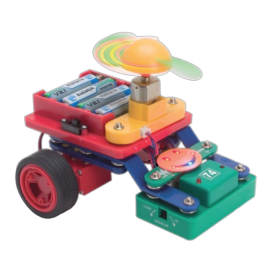
- Página 90 Coloque el interruptor en la posición de 6V La sensibilidad y la velocidad del CI 74 es ajustada de fábrica. SI desea ajustarlos mueva las perillas hacia la derecha o izquierda. 408.- Carro trazador de ruta Encienda el interruptor, el carro se moverá a través de una línea negra previamente dibujada.
- Página 91 Se mueve siguiendo la línea negra Coloque el interruptor en la posición de 6V 409.- Patrulla trazadora de ruta Encienda el interruptor, el carro emitirá el sonido de una patrulla. Cuando el carro se esté moviendo por la línea negra, el carro cambiará el sonido de la patrulla por una ametralladora.
- Página 92 Coloque el interruptor en la posición de 6V 412.- Carro trazador de ruta con sonido de guerra del espacio Encienda el interruptor, el carro a lo largo de la línea negra emitirá el sonido de la guerra del espacio. ESPAÑOL-93...
- Página 93 Coloque el interruptor en la posición de 6V 413.- Carro trazador de ruta con ventilador Encienda el interruptor, el carro se moverá por la línea negra y el ventilador se moverá indirectamente. 414.- Carro trazador de ruta con ventilador de color Reemplace el ventilador amarillo por el ventilador de colores.
- Página 94 Coloque el interruptor en la posición de 6V 415.- Carro trazador de ruta a la moda (1) Coloque el ventilador en el motor, y conecte el LED 1. 416.- Carro trazador de ruta a la moda (2) Coloque el ventilador en el motor, y conecte el LED 2. 417.- Carro trazador de ruta a la moda (3) Coloque el ventilador de colores en el motor, y conecte el LED 2.
-
Página 95: Solución De Problemas
El diseño del producto y las especifi caciones pueden cambiar sin previo aviso. previo aviso. Steren no es responsable por daños en las piezas debido a Steren no es responsable por daños en las piezas debido a conexiones incorrectas. conexiones incorrectas. -
Página 96: Lista De Proyectos
LISTA DE PROYECTOS ESPAÑOL-97... - Página 97 ESPAÑOL-98...
- Página 98 ESPAÑOL-99...
- Página 99 ESPAÑOL-100...
- Página 100 ESPAÑOL-101...
- Página 101 ESPAÑOL-12...
-
Página 102: Póliza De Garantía
1.- Para hacer efectiva la garantía, presente ésta póliza y el producto, en donde fue adquirido o en Electrónica Steren S.A. de C.V. 2.- Electrónica Steren S.A de C.V. se compromete a reparar el producto en caso de estar defectuoso sin ningún cargo al consumidor. Los gastos de transportación serán cubiertos por el proveedor. -
Página 103: Datos Del Distribuidor
DATOS DEL DISTRIBUIDOR Nombre del Distirbuidor Domicilio Producto Marca Modelo Número de serie Fecha de entrega... - Página 104 Biólogo MaximIno Martínez No. 3408 Int. 3 y 4, San Salvador Xochimanca, México, D.F. 02870, RFC: SPE941215H43 ELECTRONICA STEREN DEL CENTRO, S.A. DE C.V. Rep. del Salvador 20 A y B, Centro, 06000, México. D.F. RFC: ESC9610259N4 ELECTRONICA STEREN DE GUADALAJARA, S.A.
- Página 105 Centro de Atención a Clientes, en donde con gusto le atender- emos en todo lo relacionado con su producto Steren. Centro de Atención a Clientes...
- Página 107 / or quickly drain the batteries. Only connect the ICs using confi gurations given in the projects, incorrectly doing so may damage them. Steren is not responsible for parts damaged due to incorrect wiring. • Always use eye protection when experimenting on your own.
- Página 108 WARNING SHOCK HAZARD Never connect snap circuits to the electrical outlets in your home in any way! HOW TO USE THE PARTS The snap circuit kit uses building blocks with snaps to build the different electrical and electronic circuits in the projects. Each block has a function: there are switch blocks, lamp blocks, battery blocks, different length wire blocks, etc.
- Página 109 This is a wire block which is blue and comes in different wire lengths. To build each circuit, you have a power source block number that need AA batteries (batteries are not included with the snap circuit kit). A large clear plastic base grid is included with this kit to help keep the circuit block together.
- Página 110 PART LIST (Colors and styles may vary) Number Description Item 2 snap connectors 2 soft wires 6 two-snap connector 4 three-snap connector 2 3A 1 3B 2 bend wire 1 four-snap connector 1 five-snap connector 1 Six-snap connector 2 #9 1 vibrating switch 1 buzzer ENGLISH-05...
- Página 111 Number Description Item 1 touch plate 1 dry reed switch 1 press switch 1 slide switch 1 photosensor (CdS) 1 LED 1 2,5V lamp 1 battery compartment 1 speaker ENGLISH-06...
- Página 112 Number Description Item 1 musical IC 1 DC motor 1 resistor 1 transmission tube 1 receiver tube 1 alarm 1 war space IC 1 control module 1 connector ENGLISH-07...
- Página 113 Number Description Item 1 yellow fan 1 colour fan 2 gear case 2 wheel 1 magnet 1 flashing LED 1 flashing LED 6 plastic fastener 1 bulb ENGLISH-08...
- Página 114 PROJECTS Shift the switch to 3V position 1.- Lamp Turn on the slide switch 15, the lamp 18 will light up. Turn of the switch 15, and the lamp 18 will switch off. 2.- Hand-controlled lamp Replace the slide switch 15 with press switch 14. Press the switch 14,, the lamp will light up.
- Página 115 Shift the switch to 3V position 4.- Electric fan Assemble the circuit and make sure the slide switch 15 is off at that moment. Turn the switch 15 on and the fan will spin round. Release the switch 15 and the fan will stop. 5.- Hand-controlled fan Replace the slide switch 15 with the press switch 14.
- Página 116 6.- Magnet-controlled fan Replace the slide switch 15 with the switch 13. Place a magnet close to the switch and the fan will spin round. Take the magnet away from the switch and the fan will stop. 7.- Color fan Replace the yellow fan with a color fan, turn the switch 15 on, the fan will spin round and fl...
- Página 117 Shift the switch to 3V position 10.- Speaker Press the switch 14 and the speaker 20 will sound. ENGLISH-12...
- Página 118 Shift the switch to 3V position 11.- Lamp and motor connected in series Do not connect the yellow fan on motor 24, turn the switch 15 on, the lamp 18 will light up and the motor will spin round (sometimes you will need to rotate the pivot with hand).
- Página 119 Shift the switch to 3V position 12.- Lamp and motor connected in parallel Turn the switch 15 on, the fan will spin round and the lamp will light up. Turn the switch 15 off, the fan will stop and the bulb will switch off. ENGLISH-14...
- Página 120 Shift the switch to 3V position 13.- LED Turn the switch 15 on, the LED 17 will light up. Turn the switch off and the LED will put off. 14.- Directivity of a LED Reverse the LED 17, then turn the slide switch on, the LED will not light ENGLISH-15...
- Página 121 Shift the switch to 3V position 15.- LED and lamp connected in series Turn the switch 15 on, the LED 17 will light up but not the lamp. It is because the LED only needs a small quantity of current and the lamp needs higher than LED and the circuit only handle small quantity of current.
- Página 122 Shift the switch to 3V position 17.- LED and motor connected in series Turn the switch 15 on, the motor 24 will not spin round but the LED. 18.- LED and motor reversely connected in series Reverse the LED, turn the switch 15 on, the motor and LED will not work.
- Página 123 19.- Lamp and speakers connected in series Turn the switch 15 on, the lamp will light up dimly. Shift the switch to 3V position Shift the switch to 3V position 20.- Lamp and speaker connected in parallel. Turn the switch 15, the lamp will light up and the speaker will emit a sound.
- Página 124 Shift the switch to 3V position 21.- Series-parallel connection Turn the switch 15 on, the motor will spin round, the LED and lamp will light up. Shift the switch to 3V position 22.- LED, motor and lamp connected in parallel Operate as last project.
- Página 125 23.- Conductor tester With this conductor tester you may identify which daily life items are conductors or not. To do this, you only need to bridge the article to be tested between A and B. If the lamp lights up, the item is a conductor (may be a knife or aluminum pot).
- Página 126 Shift the switch to 3V position 26.- Electronic devices controlled respectively Assemble the circuit. The lamp 18 is controlled by press switch 14, and the motor is controlled by the slide switch. The household appliances in our daily life such as lamps, TV sets, refrigerators, etc. are connected in parallel and are controlled by different switches.
- Página 127 Shift the switch to 3V position 27.- Alternative lighting up of magnet-controlled lamp and LED When the slide switch 15 is turned on, only the LED will light up. Bring a magnet close to the switch 13, the LED will switch off and the lamp will light up.
- Página 128 Shift the switch to 3V position 31.- Magnet-controlled variable brightness lamp Turn the switch 15 on, control the switch 13 with a magnet, brightness will be variable. 32.- Hand-controlled variable brightness lamp Replace the switch 13 with the press switch 14, press the switch 14 and the brightness of the lamp will be variable.
- Página 129 Shift the switch to 3V position 33.- Magnet-controlled variable speed fan Turn the switch 15 on, control the switch 14 with a magnet, the speed of the fan will be variable. 34.- Magnet-controlled variable speed colour fan Replace the yellow fan with the color fan, the operation is the same as last project.
- Página 130 Shift the switch to 3V position 36.- Flying pan Place the yellow fan on the motor, press the switch 14, when the motor reaches the top of the speed, the pan will fl y up into the air (keep your head out of the way!) Question: Why did the yellow fan fl...
- Página 131 38.- AND gate of a lamp Turn the switch 15 on, press the switch 14, the lamp will light up. This is what an AND gate means. 39.- AND gate of a motor Turn the switch 15 on, press the switch 14, the motor will spin round.
- Página 132 41.- OR gate of a lamp Turn the switch 15 or press the switch 14, the LED will light up. This is what an OR gate means. 42.- OR gate of a motor Turn the switch 15 or press the switch 14, the motor will spin round.
- Página 133 44.- OR gate of series connections Turn the switch 15 or press the switch 14, the lamp will light up and the motor will spin round. 45.- NOT gate of a lamp Press the switch 14, the lamp will not light up. This is what a NOT gate means.
- Página 134 Shift the switch to 3V position 47.- NOT-AND gate of a LED Replace the switch to connect with the switch 14 in series, when the switch 15 and the switch 14 are closed, the LED will light up. This is what a NOT-AND gate means.
- Página 135 Shift the switch to 3V position 50.- NOT-OR gate of a LED Replace the slide switch 15 to connect the switch 14 in parallel, when any one of the switches is closed, the LED will light up. This is what a NOT-AND gate means.
- Página 136 Shift the switch to 3V position 53.- AND gate of a sound generator In the diagram, in order to make sound, the slide switch 15 and the switch 14 must be closed a the same time. 54.- OR gate of a sound generator Reconnect the switch 15 and the switch 14 in parallel.
- Página 137 Shift the switch to 3V position 55.- NOT gate of a sound generator When the slide switch 15 is on, it won’t generate any sound. 56.- NOT-AND gate of a sound generator Connect the slide switch 15 and the switch 14 in series. Only if the switch 15 and the switch 14 are closed at the same time, it won’t generate any sound.
- Página 138 58.- LED character of infrared transmitting tube Turn the switch 15, the LED will light up dimly. This indicates that the transmission tube 70 is in the status of admittance. Turn round the infrared transmitter tube, the LED will not light up, it indicates the transmission tube 70 is Shift the switch to 3V position unidirectional in conductivity.
- Página 139 60.- Hand-controlled music doorbell. Turn the slide switch 15 on, the speaker will emit a sound. When the music stops, the music can be controlled by the switch 14. 61.- Magnet-controlled music doorbell Replace the switch 14 by the switch 13, you can control the doorbell with a magnet.
- Página 140 63.- Water-controlled music doorbell If the switch 14 is replaced with a touch plate 12, the music will sound when water drips onto the touch plate. 64.- Sound-controlled music doorbell (1) Connect the buzzer 11 to A and B terminals. When the music stops, clap or speak loudly, the music will continue.
- Página 141 68.- Vibration-controlled music doorbell (1) Turn the switch 15 on, when the music stops, touch the plate 10 installed in the bottom of the circuit, the music will resume. 69.- Time-delay hand-controlled music doorbell (1) Replace the vibrating switch 10 with the switch 14, press once, the music will resume.
- Página 142 71.- Time-delay hand-controlled music doorbell (2) Replace the LED with the switch 14, press the switch 14 and the music will continue. 72.- Time-delay hand-controlled music doorbell (3) Remove the vibrating switch 10 and place a LED. Connect the switch 14 to A and B terminals, press the switch 14 only, the music will resume.
- Página 143 76.- Hand-controlled LED Turn the switch 15 on, when the LED switch off, you can control the LED pressing the switch 14. 77.- Magnet-controlled LED Replace the switch 14 with the switch 13, you can control the LED with a magnet. 78.- Light-controlled LED Replace the switch 14 with the photosensor 16, now you can con...
- Página 144 81.- Time-delay sound-controlled LED (2) Connect the buzzer to B and C terminals, repeat the operation of the last project. 82.- Time-delay sound-controlled LED (3) Connect the speaker to A and B terminals, when the LED switch off, clap loudly to the speaker and the Led will light up for a short time. 83.- Time-delay sound-controlled LED (4) Connect the speaker 20 to B and C terminals, then repeat the process of the last project.
- Página 145 86.- Time-delay vibration- controlled LED (1) Turn the switch 15 on, when the LED switch off, touch the vibrating plate, the LED will light up, and switch off after a short time. 87.- Time-delay hand-controlled LED (1) Replace the vibrating switch 10 with the switch 14, the LED will light up for a moment.
- Página 146 89.- Time-delay hand-controlled LED (2) Replace the resistor 30 with the switch 14, press the switch 14 and the LED will light up for a moment. 90.- Time-delay hand-controlled LED (3) Remove the vibrating switch 10, place the resistor 30, connect the switch 14 to A and B terminals, then press the switch 14, the LED will light up for a short of time.
- Página 147 94.- Hand-controlled fl ashing lamp Turn the switch 15, when the lamp switch off, you can control it pressing the switch 14. 95.- Magnet-controlled fl ashing lamp Replace the switch 14 with the switch 13, you can control it using a magnet. 96.- Light-controlled fl...
- Página 148 98.- Time-delay sound-controlled fl ashing lamp (1) Connect the buzzer 11 to A and B terminals, when the lamp 18 turns off, clap and the lamp will light up again for a short time. 99.- Time-delay sound-controlled fl ashing lamp (2) Connect the buzzer 11 to B and C terminals.
- Página 149 104.- Time-delay vibration- controlled fl ashing lamp Turn the switch 15 on, when the lamp switch off, touch the vibrating plate, the lamp will light up and turn it off after a period of time. 105.- Time-delay hand- controlled fl ashing lamp Replace the vibrating switch 10 with the switch 14, then press the switch...
- Página 150 107.- Time-delay hand controlled fl ashing lamp (2) Replace the resistor 30 with the switch 14, press the switch 14, the lamp will light up again and turn it off after a moment. 108.- Time-delay hand-controlled fl ashing lamp (3) Remove the vibrating switch 10, install the resistor 30, connect the switch 14 to A and B terminals, press the switch 14, the lamp will fl...
- Página 151 112.- Hand-controlled singing motor Turn the switch 15 on, when the music stops, the motor 24 will sound after pressing the switch 14. 113.- Magnet-controlled singing motor Replace the switch 14 with the switch 13, the motor 24 will sound after placing a magnet close to the switch.
- Página 152 116.- Time-delay sound-controlled singing motor (1) Connect the buzzer 11 to A and B terminals, when the music stops, clap loudly, the motor 24 will sound. 117.- Time-delay sound-controlled singing motor (2) Connect the buzzer 11 to B and C terminals. Repeat the operation as last project.
- Página 153 120.- Time-delay vibration- controlled singing motor (1) Turn the switch 15 on, when the music stops, know the plate slightly, the motor 24 will sound. 121.- Time-delay hand-controlled singing motor (1) Replace the vibrating switch 10 with the switch 14, press the switch 14, the motor 24 will sound.
- Página 154 123.- Time-delay hand-controlled singing motor (2) Replace the resistor 30 with the switch 14, press the switch 14, the motor 24 will sound. 124.- Time-delay hand-controlled singing motor (3) Remove the vibrating switch 10, place the resistor 30. Connect the switch 14 to A and B terminals, press the switch 14, the motor 24 will light up.
- Página 155 Shift the switch to 3V position 128.- Hand-controlled acoustic-optic buzzer Turn the switch 15 and wait until the music stops. Then press the switch 14, the buzzer 11 and the LED will turn on. 129.- Magnet-controlled acoustic-optic buzzer Replace the switch 14 with the switch 13, the effect can be controlled by a magnet.
- Página 156 131.- Water-controlled acoustic-optic buzzer Replace the switch 14 with a touch plate 12, the effect can be controlled by water. 132.- Sound-controlled acoustic-optic buzzer (1) Connect the speaker 20 to A and B terminals, the effect can be controlled by sound. 133.- Sound-controlled acoustic-optic buzzer (2) Connect the speaker 20 to terminals B and C, the effect can be controlled by sound.
- Página 157 Shift the switch to 3V position 136.- Time-delay hand controlled acoustic-optic buzzer (1) 137.- Time-delay hand controlled acoustic-optic buzzer (2) 138.- Time-delay hand controlled acoustic-optic buzzer (3) 139 – 141.- Time-delay magnet-controlled acoustic-optic buzzer (1) – (3) ENGLISH-52...
- Página 158 Shift the switch to 3V position 142.- Hand-controlled fl ashing music doorbell 143.- Magnet-controlled fl ashing music doorbell 144.- Light-controlled fl ashing music doorbell 145.- Water-controlled fl ashing music doorbell 146.- Sound-controlled fl ashing music doorbell (1) 147.- Sound-controlled fl ashing music doorbell (2) 148.- Motor-controlled fl...
- Página 159 Shift the switch to 3V position 150.- Time-delay hand-controlled fl ashing music doorbell (1) 151.- Time-delay hand-controlled fl ashing music doorbell (2) 152.- Time-delay hand-controlled fl ashing music doorbell (3) 153 – 155.- Time-delay magnet-controlled fl ashing music doorbell (1) – (3) ENGLISH-54...
- Página 160 Shift the switch to 3V position 156.- Hand-controlled adjustable music sound 157.- Magnet-controlled adjustable music sound 158.- Water-controlled adjustable music sound 159 – 161.- Sound-controlled adjustable music sound (1) – (3) 162 – 164.- Motor-controlled adjustable music sound (1) – (3) ENGLISH-55...
- Página 161 Shift the switch to 3V position 165 – 167.- Time-delay hand-controlled adjustable music sound (1) – (3) 168 – 170.- Time-delay magnet-controlled adjustable music sound (1) – (3) ENGLISH-56...
- Página 162 Shift the switch to 3V position 171.- Hand-controlled acoustic-optic motor sound Turn the switch 15 and wait until the music stops. Press the switch 14, the LED will light up and the motor will emit music. 172.- Magnet-controlled acoustic-optic motor sound 173.- Light-controlled acoustic-optic motor sound 174.- Water-controlled acoustic-optic motor sound 175 –...
- Página 163 Shift the switch to 3V position 179 – 181.- Time-delay hand-controlled acoustic-optic motor sound (1) – (3) 182 – 184.-Time-delay magnet-controlled acoustic-optic motor sound (1) – (3) ENGLISH-58...
- Página 164 Shift the switch to 3V position 185.- Hand-controlled acoustic-optic music doorbell 186.- Magnet-controlled acoustic-optic music doorbell 187.- Light-controlled acoustic-optic music doorbell 188.- Water-controlled acoustic-optic music doorbell 189.- Sound -controlled acoustic-optic music doorbell (1) 190.- Sound-controlled acoustic-optic music doorbell (2) 191.- Motor-controlled acoustic-optic music doorbell (1) 192.- Motor-controlled acoustic-optic music doorbell (2) ENGLISH-59...
- Página 165 Shift the switch to 3V position 193 – 195.- Time-delay hand-controlled acoustic-optic music doorbell (1) – (3) 196 – 198.- Time-delay magnet-controlled acoustic-optic music doorbell (1) – (3) ENGLISH-60...
- Página 166 Shift the switch to 3V position 199.- Hand controlled fl ashing motor sound Turn the switch 15 on, wait until the music stops. Press the switch 14 and the lamp 18 will light up, then the motor will emit music too. 200.- Magnet-controlled fl...
- Página 167 Shift the switch to 3V position 207 – 209.- Time-delay hand-controlled fl ashing motor sound (1) – (3) 210 – 212.- Time-delay magnet-controlled fl ashing motor sound (1) – (3) ENGLISH-62...
- Página 168 213.- Turning the motor off and acoustic-optic music Turn the switch 15 on, when the music stops, press the switch 14, the music will be listened in the speaker. 214.- Turning the motor off and time-delay LED Replace the speaker 20 with the LED 17, then operate as the last project.
- Página 169 217.- Turning the motor off and fl ashing music Connect the LED to C and D terminals, then operate as last project. 218.- Turning the motor off and acoustic-optic sound of buzzer Replace the speaker 20 with the buzzer 11, then connect it with the LED 17 in parallel, operate as the last project.
- Página 170 221.- Hand-controlled sound of a buzzer Turn the switch 15 on, when the music stops, press the switch 14 to control it. 222.- Magnet-controlled sound of a buzzer Replace the switch 14 with the switch 13, then you can control the music with a magnet.
- Página 171 225.- Sound-controlled sound of a buzzer (1) Connect the speaker 20 to A and B terminals, when the music stops, clap loudly, the buzzer 11 will emit sounds. 226.- Sound-controlled sound of a buzzer (2) Connect the speaker 20 to B and C terminals. 227.- Motor-controlled sound of a buzzer (1) Replace the motor 24 with a lamp 18, connect the motor 24 to A and B terminals, when the music stops, turn the motor shaft slightly, the buzzer...
- Página 172 229.- Time-delay vibration-controlled sound of a buzzer Turn the switch 15, when the music stops, knock the touch plate slightly, the buzzer 11 will emit music. 230.- Time-delay hand-controlled sound of a buzzer (1) Replace the vibrating switch 10 with a switch 14, then press the switch 14, and the buzzer 11 will emit music.
- Página 173 233.- Time-delay music-controlled sound of a buzzer (3) Remove the vibrating switch 11, place the resistor 30. Connect the switch 14 to A and B terminals, press the switch 14,m the buzzer will emit sounds. 234.- Time-delay magnet-controlled sound of a buzzer Replace the vibrating switch 10 with a switch 13, bring a magnet close the switch 13, the buzzer 11 will emit music.
- Página 174 237.- Hand-controlled acoustic- optic doorbell 238.- Ma gnet-controlled acoustic- optic doorbell 239.- Light-controlled acoustic-optic doorbell 240.- Water-controlled acoustic- optic doorbell 241.- Sound-controlled acoustic- optic doorbell (1) 242.- Sound-controlled acoustic- optic doorbell (2) 243.- Motor-controlled acoustic- optic doorbell (1) 244.- Motor-controlled acoustic- optic doorbell (2) Shift the switch to 3V position The operation of these circuits is the same as the projects 60 to 67.
- Página 175 245.- Vibration-controlled acoustic- optic doorbell (1) 246.- Time-delay hand-controlled acoustic-optic doorbell (1) 247.- Time-delay vibration- controlled acoustic-optic doorbell 248.- Time-delay hand-controlled acoustic-optic doorbell (2) 249.- Time-delay hand-controlled acoustic-optic doorbell (3) The operation of these projects is the same as in the projects 68 to 250.- Time-delay magnet-controlled acoustic-optic doorbell (1) 251.- Time-delay magnet-controlled...
- Página 176 253.- Flashing lamp with music Turn the switch 15 on, when the music stops, press the switch 14, the lamp 18 will fl ash, and the music will stop. 254.- Time-delay fl ashing LED Replace the speaker 20 with a LED, then press the switch 14, the lamp 18 will fl...
- Página 177 257.- Playing music while shutting the motor Replace the lamp 18 with the motor 24 (do the same for next item), replace the speaker 20 to the original place, then press the switch 14 once, the speaker 20 will emit a sound. 258.- Time-delay lights up a LED while shutting the motor off Replace the speaker 20 with a LED, press the switch 14 once, the LED will light up for a short time.
- Página 178 261.- Vibration-controlled doorbell with rhythmic music (1) Connect the vibrating-switch 10 to A and B terminals, when the music stops, knock the touch plate slightly, and the speaker will emit a slow-rhythm music (If you cannot get the desired effect, use a resistor or capacitor to connect it parallel over the LED).
- Página 179 265.- Hand-controlled doorbell with rhythmic music (1) Connect the switch 14 to A and B terminals, then press the switch 14 and the speaker 20 will emit rhythmic music. 266.- Hand-controlled doorbell with rhythmic music (2) Connect the switch 14 to terminals B and C. 267.- Hand-controlled doorbell with rhythmic music (3) Connect the switch 14 to D and E terminals.
- Página 180 275.- Police car sound (1) Turn the switch 15 on, the alarm 72 will emit a police car sound. 276.- Machine gun sound (1) Connect the A and B terminals with a soft wire, turn the switch 15 on, the alarm 72 will emit a machine gun sound.
- Página 181 280.- Gun machine sound (2) Connect the A and B terminals with a soft wire, then press the switch 14, the alarm 72 will emit a gun machine sound. 281.- Fire engine sound (2) Connect the E and B terminals with a soft wire, press the switch14, the alarm 72 will emit a fi...
- Página 182 287.- Police car slow speed sound Turn the switch 15 on, the alarm 72 will emit a police car sound, install a resistor over the LED to change the sound effect. Shift the switch to 3V position 288.- Gun machine slow speed sound Connect the A and B terminals, the alarm will emit a gun machine sound.
- Página 183 Shift the switch to 3V position 292.- Hand-controlled space war sound (1) Turn the switch 15, the IC 73 will emit a war space sound. 293.- Hand-controlled space war sound (2) Press the switch 14, the IC 73 will emit a war space sound. 294.- Magnet-controlled space war sound Replace the switch 15 with the switch 13, the sound will be controlled by a magnet.
- Página 184 295.- Light-controlled space war sound Replace the switch 15 with a photosensor 16, the sound can be controlled by light 296.- Touch-controlled space war sound Replace the switch 14 with a touch plate 12, the sound can be controlled touching the plate. 297.- Knock-controlled space war sound Replace the switch 14 with a vibrating plate 10, the sound can be controlled knocking the plate slightly.
- Página 185 298.- Sensitive fan (1) Insert the connector to terminal A, keep the infrared tube out of the CI 74 control modules, come and go by the black and white side of the barn door, respectively. The you can control the spped of the fan. 299.- Sensitive fan (2) Insert the connector to terminal B.
- Página 186 304.- Sensitive gun machine sound (1) Turn the switch 15 on, the alarm 72 will emit a car police sound. Keep the infrared tube out of the black and white sides of the barn door respectively, then the sound will change to a gun machine. 305.- Sensitive gun machine sound (2) Connect the B and E terminals, with a soft wire, turn the switch 15, the alarm 72 will emit a fi...
- Página 187 307.- Breakage and anti- theft warning After connecting the circuit, if you connect the A and B terminals with a wire, the space war sound will stop. When you try the anti-theft system, you can place a long and thin cable through the desired object to protect (such as bicycle, cars, doors,...
- Página 188 309.- Nose warning (1) 310.- Noise warning (2) Connect the buzzer 11 to A and B or B and E terminals, if the environment is very noise, the speaker 20 will emit a sound. 311.- Knock-style music doorbell (1) 312.- Knock-style music doorbell (2) Install the buzzer 11 at the middle of the door, then connect a soft wire to A and B or B and E...
- Página 189 315.- Anti-theft warning with night light 316.- Daybreak warning Connect the photosensor 16 to C and D terminals, the speaker 20 will no emit any sound, if the intruder turns the light on, or when the daybreak lights the circuit, the speaker will emit a sound. 317.- Baby urine alarm Connect the touch plate 12 to C and D terminals, place it under the baby’s bed, if the urine of the baby drops into the touch plate 12, the...
- Página 190 Shift the switch to 3V position 320 – 329.- LEDs alarm connected in series 330 – 336.- Flashing lamp alarm connected in series 337 – 344.- Sound alarm with motor connected in series Replace the LED with a motor 24, then you can assemble up to 8 different types of motor alarm.
- Página 191 Shift the switch to 3V position 345 – 354.- Lamp and sound alarm connected in series 355 – 361.- Flashing lamp and sound alarm with motor connected in series Reconnect the motor 24 with the lamp 18 in series, you can assemble up to 7 different IC types.
- Página 192 Shift the switch to 3V position 362 – 371.- Acoustic-optic alarm connected in series 372 – 381.- Acoustic-optic buzzer alarm connected in series Replace the speaker 20 with the buzzer 11. You can assemble up to 10 different alarms (the noise alarm is replaced with the speaker 20 and it is connected to A and B terminals.
- Página 193 390 – 397.- Motor alarm and buzzer connected in series Reconnect the motor 24 with the buzzer 11 in parallel. You can assemble up to 8 different types of alarms. 398 – 407.- Flashing lamp and music alarm connected in series Reconnect the lamp 18 with the buzzer 11 in series.
- Página 194 Shift the switch to 6V position Sensitivity and speed of the IC 74 have been adjusted previosuly, if you want to adjust them turning the knobs to the left or right. 408.- Tracer car Turn the switch on, the car will move over a previous painted black line. ENGLISH-89...
- Página 195 Moves through a black line Shift the switch to 6V position 409.- Tracer police car Turn the switch on, the car will emit a police car sound. When the car is moving throughout the black line, the sound will change for a gun machine.
- Página 196 Shift the switch to 6V position 412.- Tracer car with war space sound Turn the switch on, while the car is moving, it will emit the war space sound. ENGLISH-91...
- Página 197 Shift the switch to 6V position 413.- Tracer car with fan Turn the switch on, while the car is moving throughout the black line, the fan will rotate. 414.- Tracer car with colour fan Replace the yellow fan with a colour fan ENGLISH-92...
- Página 198 Shift the switch to 6V position 415.- Fashion tracer car Place the fan on the motor, then connect the LED 1. 416.- Fashion tracer car (2) Place the fan on the motor, then connect the LED 2. 417.- Fashion tracer car (3) Place the colour fan on the motor, then connect the LED 2.
- Página 199 Product design and specifi cations are subject to change, without Product design and specifi cations are subject to change, without notice. notice. Steren is not responsible for parts damaged due to incorrect Steren is not responsible for parts damaged due to incorrect wiring. wiring.
- Página 200 PROJECT LISTINGS ENGLISH-95...
- Página 201 ENGLISH-96...
- Página 202 ENGLISH-97...
- Página 203 ENGLISH-98...
- Página 204 ENGLISH-99...
- Página 205 ENGLISH-100...
- Página 206 Part number: K-810 Brand: Steren WARRANTY This Steren product is warranted under normal usage against defects in workmanship and materials to the original purchaser for one year from the date of purchase. CONDITIONS 1.- This warranty card with all the required information, invoice or purchase ticket, product box or package, and product, must be presented when warranty service is required.
- Página 207 RETAILER INFORMATION Name of the retailer Address Product Brand Part number Serial number Date of delivery...
- Página 208 In case your product fails or have questions, please contact your nearest dealer. If you are in Mexico, please give a call to our Call Center. Call Center 01 800 500 9000...