Tabla de contenido
Publicidad
Idiomas disponibles
Idiomas disponibles
Enlaces rápidos
Publicidad
Tabla de contenido

Manuales relacionados para Multimetrix CM600


Resumen de contenidos para Multimetrix CM600
- Página 1 PINCE AMPEREMETRIQUE DIGITAL CLAMP METER MULTIMETER MESSZANGE MULTIMETRO MULTIMERICA CM600 CM610 CM625 FR A N Ç A IS Notice de fonctionnement E N G L I S H User’s manual D E U T S C H...
- Página 2 Français ..................2 English ..................10 Deutsch ................... 18 Italiano ..................26 Español ................... 34...
-
Página 3: Precautions D'emploi
CONDITIONS GENERALES DE GARANTIE ET DE SECURITE 1. PRECAUTIONS D’EMPLOI Lisez les instructions de sécurité ci-dessous avant toute utilisation de l’appareil, afin d’éviter les accidents corporels, tels que brûlures et chocs électriques. Suivez impérativement les indications précédées du symbole 1.1 DEFINITION DES CATEGORIES D’INSTALLATION (cf. -
Página 4: Recommandations Diverses De Securite
Les doigts ne doivent jamais dépasser la garde de la pointe de touche. Ne mettrez jamais les doigts en contact avec la partie métallique de la pointe de touche. Vérifiez la qualité mécanique et électrique des cordons et des pointes de touche avant toute mesure. -
Página 5: Presentation
Repère Fonction Borne négative noire (-) COM Afficheur à cristaux liquides : - CM600 / CM610 : 3 digits ½ (1999 points) - CM625 : 4 digits (4369 points) ‘----‘ : dépassement de capacité en mesure de courant et tension Sélecteur rotatif de fonction... - Página 6 Le conducteur doit être localisé au centre de cette zone durant la mesure pour une précision maximale. Touche MAX (CM600 et CM610 ) : pour les fonctions affiche la valeur maximale mesurée ; cette dernière est automatiquement mise à...
-
Página 7: Mesure De Tension
L’affichage de « ----- » indique un dépassement de capacité. - CM600 et CM610 : pour afficher les valeurs max., voir §. 7.9. - CM600 et CM610 : pour mémoriser la valeur lue, voir §. 7.10. Ouvrir la pince, libérer le conducteur et positionner le sélecteur sur OFF. -
Página 8: Mesure De Resistance
Lisez les recommandations de sécurité avant utilisation. Le circuit sera impérativement hors-tension. Gammes de mesure automatiques : CM600 et CM610 : 200 Ω ou 20 MΩ (6 gammes). CM625 : 400 Ω ou 40 MΩ (6 gammes). CM600 et CM610 : positionner le sélecteur (rep. 3) CM625 : positionner le sélecteur (rep. -
Página 9: Remplacement Des Piles
Pour désactiver la fonction , appuyer sur HOLD. 8. REMPLACEMENT DES PILES Lisez les recommandations de sécurité avant utilisation. Le circuit sera impérativement hors-tension. Remplacer les piles lorsque l’icône est affichée (rep. 17) : Déconnecter les pointes de touche. Positionner le commutateur sur OFF. Retirer vis de fixation et couvercle de logement de piles. - Página 10 (MAX) CM625 : mémorisation de mesure (Data Hold) Indication usure Symbole piles faibles piles Fréquence CM600 et CM610 : environ 3 x par s d’échantillonnage CM625 : environ 2 x par s Ouverture 30 mm maximale des mâchoires Utilisation 0 à...
-
Página 11: Precautions During Use
GENERAL SAFETY AND GUARANTEE CONDITIONS 1. PRECAUTIONS DURING USE Please read the safety instructions below before using the instrument to avoid any accidental injuries, such as burns or electric shocks. You must observe the instructions preceded by the symbol 1.1 DEFINITION OF THE INSTALLATION CATEGORIES (Cf. - Página 12 Never touch any metal part of the contact points with your finger. Check the mechanical and electrical condition of the power cables contact points before taking measurements. Any power cables or contact points that are damaged must be replaced immediately. Never use the instrument if it is damaged.
- Página 13 6.1 THE FRONT FACE Function Black negative COM terminal (-) Liquid crystal display: - CM600 / CM610: 3 ½ digits (1999 points) - CM625: 4 digits (4369 points) ‘----‘: current and voltage measurements exceed the range Function rotary selector switch...
- Página 14 For maximum accuracy, the conductor must be located in the centre of this area during measurement. MAX button (CM600 and CM610): this shows the maximum value, automatically updated, for the functions. The icon is displayed when the function is activated: pressing it again cancels the function.
- Página 15 When the AUTO icon (23) is displayed, the multimeter determines the optimum measurement range. If “-----“ is displayed, the capacity has been exceeded. - CM600 and CM610: to display the maximum value, see §. 7.9. - CM625: to store the maximum reading, see §. 7.10.
-
Página 16: Continuity Test
The buzzer sounds when the circuit to be checked is DC or has a resistance of less than 90 Ω ± 40 Ω (CM600 & CM610) or 50 Ω ± 25 Ω (CM625). - Página 17 8. TO REPLACE THE BATTERIES Please read the safety recommendations before use. There must be no voltage in the circuit. The batteries must be replaced when the icon (17) is displayed: Disconnect the contact points. Set the commutator to OFF. Remove fixing screws...
-
Página 18: Reference Conditions
CM600 & CM610: maximum measurement (Max Hold) CM625: measurement storage (Data Hold) Battery low charge Low battery symbol indication CM600 & CM610: approx. 3 x per Sampling frequency sec. CM625: approx. twice per sec. 30 mm Maximum opening of jaws 0 to 50°C (32°F - 122°F). -
Página 19: Erklärung Der Symbole
ALLGEMEINE GARANTIEBEDINGUNGEN UND SICHERHEITSHINWEISE 1. VORSICHTSMASSNAHMEN BEIM GEBRAUCH Lesen Sie die folgenden Sicherheitsanweisungen vor dem Gebrauch Gerätes, Verletzungen Verbrennungen und Stromschläge zu vermeiden. Alle mit diesem Symbol gekennzeichneten Anweisungen müssen unbedingt beachtet werden. 1.1 DEFINITION DER INSTALLATIONSKLASSEN (siehe IEC 664-1) ... - Página 20 Die Finger dürfen nie über die Absicherung an der Prüfspitze hinausragen. Die Finger dürfen keinesfalls in Kontakt mit dem Metallteil der Prüfspitze geraten. Kontrollieren Sie die mechanische und elektrische Qualität der Schnüre und der Prüfspitzen, bevor Sie mit dem Messen anfangen.
- Página 21 6.1 DIE VORDERSEITE Abb. Funktion Negative schwarze Anschlussklemme (-) COM LCD - Anzeigegerät: - CM600 & CM610: 3 Ziffern ½ (1.999 Punkte) - CM625: 4 Ziffern (4.369 Punkte) ‘----‘: Bereichsüberschreitung bei der Strom- und Spannungsmessung Drehbarer Funktionsauswahlknopf OFF: ausgeschaltetes Universalmessgerät : Wechselstrom (CM600 &...
-
Página 22: Die Rückseite
Für die Erlangung eines Höchstmaßes an Präzision muss der Leiter während der Messung in der Mitte dieses Bereiches lokalisiert werden. Taste MAX (CM600 & CM610): für die Funktionen zeigt den gemessenen Höchstwert an; dieser Wert wird automatisch aktualisiert. Das Symbol wird angezeigt, wenn die Funktion aktiviert ist;... - Página 23 Bitte lesen Sie vor der Verwendung aufmerksam die Sicherheitshinweise durch. Automatische Messbereiche: CM600 & CM610: 200 mVDC bis 600 VDC (5 Bereiche) 2 VAC bis 600 VAC (4 Bereiche). CM625: 4 VDC bis 600 VDC (4 Bereiche) und 4 VAC bis 600 VAC (4 Bereiche).
-
Página 24: Messung Des Widerstandes
Kreislauf muss unbedingt spannungsfrei sein. Automatische Messbereiche: CM600 & CM610: 200 Ω oder 20 MΩ (6 Bereiche). CM625: 400 Ω oder 40 MΩ (6 Bereiche). CM600 & CM610: bitte stellen Sie den Auswahlknopf CM625: bitte stellen Sie den Auswahlknopf auf Setzen Sie bitte die schwarze Leitungsschnur in die Anschlussklemme COM (Abb. - Página 25 Widerstand 90 Ω ± 40 Ω (CM610) und 50 Ω ± 25 Ω (CM625) unterschreitet. Stellen Sie den Auswahlknopf nun bitte auf OFF. 7.9 FUNKTION MAX (ANZEIGE DES HÖCHSTWERTES - CM600 & CM610) Bitte stellen Sie den Auswahlknopf auf oder und betätigen Sie nun die Taste MAX.
- Página 26 CM600 & CM610: Höchstmessung (Max Hold) CM625: Speicherung der Messung (Data Hold) Angabe des Symbol Batterieschwäche Batterieverbrauchs CM600 & CM610: etwa 3 Mal pro Stichprobenfrequenz Sek. CM625: etwa 2 Mal pro Sek. Max. Oeffnung der 30 mm Zangenbacken 0 bis 50°C (32°F - 122°F) RH < 80%,...
-
Página 27: Avvertenze Per L'uso
CONDIZIONI GENERALI DI GARANZIA E SICUREZZA 1. AVVERTENZE PER L’USO Leggere le seguenti istruzioni di sicurezza prima di qualsiasi uso dell’apparecchio, per evitare incidenti fisici quali bruciature e scosse elettriche. Le disposizioni precedute simbolo vanno rigorosamente rispettate. 1.1 DEFINIZIONE DELLE CATEGORIE DI IMPIANTO (cfr. - Página 28 Le dita non devono mai superare il livello del puntale del tasto. Non mettere mai le dita in contatto con la parte metallica del puntale del tasto. Controllare la qualità meccanica ed elettrica dei cavi e dei puntali di tasto prima di ogni misurazione.
- Página 29 4. MANUTENZIONE 4.1 VERIFICHE METROLOGICHE Come ogni apparecchio di misurazione o di test, è necessaria una verifica periodica. Informazioni e dati a richiesta o presso il vostro distributore. 4.2 MANUTENZIONE Pulire periodicamente il multimetro con un panno umido bagnato con acqua e sapone. Non utilizzare materiali abrasivi o che contengono solventi.
-
Página 30: Presentazione
6.1 LATO ANTERIORE Fig. Funzione Terminale negativo nero (-) COM Visore a cristalli liquidi : - CM600 & CM610 : 3 cifre ½ (1999 punti) - CM625 : 4 cifre (4369 punti) ‘----‘ : superamento capacità nella misurazione di corrente e tensione. -
Página 31: Lato Posteriore
Leggere le disposizioni di sicurezza prima dell’uso. Gamme di misurazioni automatiche : CM600 & CM610 : 200 mVDC a 600 VDC (5 gamme) e 2 VAC a 600 VAC (4 gamme). CM625 : 4 VDC a 600 VDC (4 gamme) e 4 VAC a 600 VAC (4 gamme). -
Página 32: Test Di Continuità
7.5 MISURAZIONE DI CORRENTE ALTERNATA Gamme di misurazioni automatiche : - CM600 & CM610 : 200 A AC o 600 A AC (2 gamme) - CM625 : 40 A AC o 400 A AC (2 gamme) Posizionare il selettore (fig. 3) su Le icone (fig. -
Página 33: Sostituzione Delle Pile
Il segnale sonoro sarà udibile quando il circuito da controllare è continuo o con resistenza inferiore a 90 Ω ± 40 Ω (CM600 & CM610) e 50 Ω ± 25 Ω (CM625). Posizionare il selettore su OFF. 7.9 FUNZIONE MAX (VISUALIZZA VALORE MASSIMO - CM600 &... -
Página 34: Caratteristiche
CM625 : Memorizzazione della mis. (Data Hold) Simbolo di pile che si stanno Indicazione usura pile scaricando CM600 & CM610 : circa 3 volte al Frequenza di secondo campionatura CM625 : circa 2 volte al secondo Apertura massimale 30 mm delle ganasce 0 - 50°C (32°F - 122°F). -
Página 35: Condiciones Generales De Garantía Y De Seguridad
CONDICIONES GENERALES DE GARANTÍA Y DE SEGURIDAD 1. PRECAUCIONES DE USO Lea las siguientes instrucciones de seguridad antes de utilizar el aparato, con el fin de evitar los accidentes corporales, como quemaduras y electrocuciones. Respete obligatoriamente las indicaciones precedidas del símbolo 1.1 DEFINICION DE LAS CATEGORIAS DE INSTALACIÓN (ver CEI 664-1) -
Página 36: Recomendaciones Diversas De Seguridad
No utilice nunca el aparato sin guantes para electricistas y otros equipamientos de seguridad recomendados por la legislación. Los dedos no deben nunca superar la protección de la punta de tecla. No poner nunca los dedos en contacto con la parte metálica de la punta de toque. -
Página 37: Mantenimiento
En caso de reenvío, utilice el embalaje original e indique, mediante una nota adjunta al aparato, los motivos de la devolución. 4. MANTENIMIENTO 4.1 VERIFICACIONES METROLÓGICAS Como cualquier aparato de medición o de ensayo, es necesaria una verificación periódica. Informaciones y datos sobre pedido o en su distribuidor. -
Página 38: Utilización
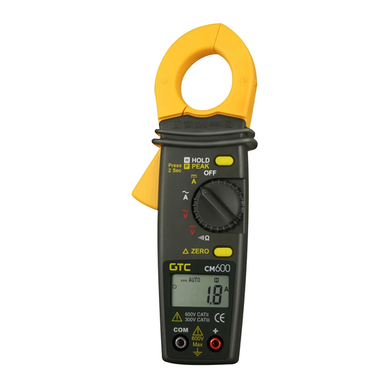
Marca. Función Borne negativo negro (-) COM Pantalla de cristales líquidos: - CM600 & CM610: 3 dígitos ½ (1999 puntos) - CM625: 4 dígitos (4369 puntos) ‘----‘: superación de la capacidad de medición de corriente y tensión Conmutador de funciones. -
Página 39: La Parte Posterior
Lea las recomendaciones de seguridad antes de utilizar. Gamas de medición automáticas: CM600 & CM610: 200 mVDC a 600 VDC (5 gamas) y 2 VAC a 600 VAC (4 gamas) CM625: 4 VDC a 600 VDC (4 gamas) y 4 VAC a 600 VAC (4 gamas) Posicionar el selector (marca 3) sobre el símbolo... -
Página 40: Medición De Corriente Alterna
Leer el valor de la corriente una vez estabilizada. Si aparece “-----”, eso indica una superación de capacidad. - CM600 & CM610: para ver los valores máximos, ver §. 7.9. - CM600 & CM610: para memorizar el valor leído, ver §. -
Página 41: Función Hold (Memorización Del Valor Leído - Cm625)
CM600 & CM610: posicionar el selector (marca 3) sobre y pulsar SELECT para ver (marca 13). CM625: posicionar el selector (marca 3) sobre pulsar SELECT para ver (marca 13). Insertar el cable negro en el borne COM (marca 1), el rojo en el borne + (marca 10) y aplicar las puntas sobre el circuito a controlar. -
Página 42: Características
CM600, CM610 & CM625: Tensiones continuas, tensiones alternas, Medición de los corriente alterna, resistencia, test de valores continuidad CM600 & CM610: test de diodos CM625:Corriente continua Método de CM610 & CM625 :True RMS AC mediciones (tensión eficaz verdadera) CM600 & CM610: 2.000 puntos Pantalla CM625: 4.369 puntos... - Página 43 CM600 & CM610 CM625 Range (A) 200/600 40/400 50 → 500 Hz 50 → 400 Hz Resolution (A) 0.1/1.0 0.01/0.1 Accuracy (±%) 1.9 + 10 dgt ±1.5 + 10 dgt (200 A) (40 A) 1.9 + 5 dgt 1.5 + 5 dgt...
- Página 44 01/2015 Code 691036A00 - Ed.7 Deutschland - Straßburger Str. 34 - 77694 KEHL /RHEIN - Tél : (07851) 99 26-0 - Fax : (07851) 99 26-60 España - C/ Roger de Flor N°293 - Planta 1 - 08025 BARCELONA - Tél : (93) 459 08 11 - Fax : (93) 459 14 43 Italia - Via Sant’...