Publicidad
Idiomas disponibles
Idiomas disponibles
Enlaces rápidos
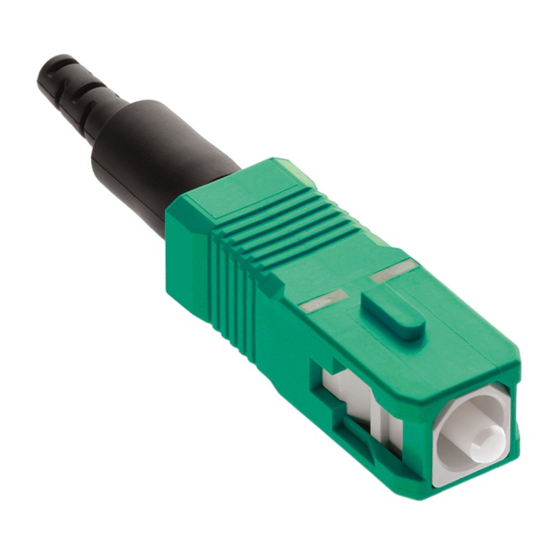
49991-ASC
FASTCAM® APC SC
Connectors
WARNING: Always wear eye protection
when handling optical fibers. Dispose of
any cut or cleaved ends properly.
NOTE: FastCAM Angled Polish Connectors
(APC) require the use of a precision angled
cleaver.
NOTE: If you are experiencing difficulty inserting your
fiber into the connector review the following steps:
A. Never force a fiber into the connector. Verify that all
acrylate coating is removed and the fiber is clean of
debris.
B. Make sure the two wedge clips are properly engaged
and the Cam is fully open (a bright light in window
#1). It is recommended to reset the wedges prior to
termination.
C. Gently twist the fiber as it is being inserted into the
connector. While the light in window #1 may not
fully disperse a noticeable dim will occur indicating a
proper insertion.
Connector Installation & Assembly Instructions
FIBER TERMINATION- 250μm
1.0
The following installation instructions describe the assembly
procedure for FastCAM connectors which allow termination on
250um, 900um, 2.0mm, and 3.0mm fiber/cable.
2.0
Identify components of the connector kit. (See Figure 1)
3.0
Tools required for installation are a precision 8º angled
cleaver, 99% isopropyl alcohol, lint free wipes, a fine-tipped felt
pen, a fiber stripper and a millimeter ruler or this Instruction
sheet marking template.
3.1
Slide the protective tubing, 250µm protective tube and
900μm boot (in order) onto the fiber. (See Figure 2)
Note: The 250µm protective tube should come attached to
protective tubing.
3.2
A minimum of 35mm from the end of the 250um fiber, place
three marks: an endpoint at 0mm, at 3.5 mm and 17 mm directly
on the top (12 o'clock position) of the fiber (See Figure A1)
3.3
Strip the fiber to the 0mm mark by removing 5-10 mm at a
time. (See Figure 3)
Clean the stripped fiber with an alcohol wipe to remove any
debris. Check the fiber integrity by bending the stripped end
slightly at 60 degrees.
3.4
Set the stripped fiber onto the fiber holder such that the
3.5mm mark is at the entrance point of the fiber holder. (See
Figure A2)
3.5
Secure the fiber with the fiber holder doors to prevent it from
shifting and follow the cleaver manufacturer's instructions. DO
NOT ALLOW THE FIBER TO ROTATE DURING THE
CLEAVING ACTION (See Figure 4)
3.6
Press the cleaving anvil downward with steady even
pressure. Hold for 0.5-1.0 second only. (See Figure 5)
3.7
Cleave the fiber and remove it from the cleaving device
*A precision angled cleaver is required for successful
termination. Those with a guaranteed maximum 8º cleave angle
for single-mode fibers provided acceptable results.
3.8
The wedge clips are engaged at shipment. If they have
become dislodged, squeeze the top and bottom of the wedge clip,
insuring it is inserted in the connector body. A click will be heard
for each wedge. (See Figure 6)
3.9
Slide the 250μm protective tubing towards the end 250μm
coating.
3.10
Insert the cleaved fiber into the rear of the connector.
Position the mark on the fiber parallel to the top center of the
connector body. Continue insertion at this aligned position until
the fiber is fully inserted to the mark. Make a bend in the fiber to
maintain connection. (See Figure 7)
3.10A
OPTIONAL: Use the Visual Fault Locator (VFL) as an
aid to determine the cleaved fiber and stubbed fiber are
connected properly. (steps A.3 to A.4)
A.3
Remove the FastCAM connector dust cap and insert the
connector into the VFL. Turn the VFL power on and there will be a
red glow in Position 1 of the wedge clip. (See Figure A3)
A.4
Insert the cleaved fiber into the rear of the connector.
Position the mark on the fiber parallel to the top center of the
connector body. Continue insertion at this aligned position until
the red glow dims in Position 1 of the wedge clip. Make a bend in
the fiber to maintain connection. (See Figures A4 and 7)
Pour les traductions en français, allez à:
Para las traducciones en español, visite:
www.leviton.com
3.11
If used, remove the VFL. Maintaining a slight force on the
fiber, release the wedge clip by squeezing both sides until the
wedge clip dislocates itself from the connector body. Remove the
wedge clip. Place the protective cap back onto the connector's
ferrule. (See Figure 8)
3.12
Slide the boot up and over the rear of the connector body.
Slide the clear 900um protective tubing - over the black 250um
protective tubing - to the back of the connector's boot.
Termination is complete. (See Figure 9)
Note: The ferrule's protective cap should remain in place until you
are ready to insert the connector.
DI-109-49991-20A
Publicidad

Manuales relacionados para Leviton FASTCAM APC SC


Resumen de contenidos para Leviton FASTCAM APC SC
- Página 1 FASTCAM® APC SC Para las traducciones en español, visite: Connectors FIBER TERMINATION- 250μm www.leviton.com The following installation instructions describe the assembly procedure for FastCAM connectors which allow termination on 250um, 900um, 2.0mm, and 3.0mm fiber/cable. Identify components of the connector kit. (See Figure 1) Tools required for installation are a precision 8º...
- Página 2 If used, remove the VFL. Maintaining a slight force on the and 17) fiber, release the wedge clip by squeezing both sides until the wedge clip dislocates itself from the connector body. Remove the wedge clip. (See Figure 31) For Technical Assistance Call: 1-800-722-2082 DI-109-49991-20A www.leviton.com/ns...
- Página 3 49991-ASC Directives d’assemblage et d’installation des connecteurs Connecteurs SC FASTCAM TERMINAISON DES FIBRES — 250 µm Les présentes directives décrivent la procédure Fourreau de TEMPLATE/MODÈLE/PLANTILLA d’assemblage des connecteurs FastCam, qui peuvent servir de 900µm Fourreau de terminaisons pour les fibres/câbles de 250 µm, de 900 µm, de ACTUAL SIZE –...
- Página 4 Remarque: le capuchon protecteur devrait rester sur la virole jusqu’au moment de l’insertion du connecteur. se tamise à la position 1 de la pince. Plier les fibres pour maintenir la connexion. (Figures A4 et 17) Pour l'assistance technique appel: 1-800-722-2082 DI-109-49991-20A www.leviton.com/ns...
- Página 5 49991-ASC Instrucciones de instalación y montaje del Conector Conectores SC/APC Terminación de fibra - 250μm FASTCAM® TEMPLATE/MODÈLE/PLANTILLA Las siguientes instrucciones de instalación describen el procedimiento de montaje de conectores FastCAM que permiten la terminación de fibra/cable de 250μm, 900um, 2.0mm y 3.0mm. ACTUAL SIZE –...
- Página 6 Para asistencia técnica llame al: hasta que el gancho de la cuña se separe por sí mismo del cuerpo 1-800-722-2082 del conector. Retire el gancho de la cuña (Vea la Figura 31). DI-109-49991-20A www.leviton.com/ns...