Tabla de contenido
Publicidad
Enlaces rápidos
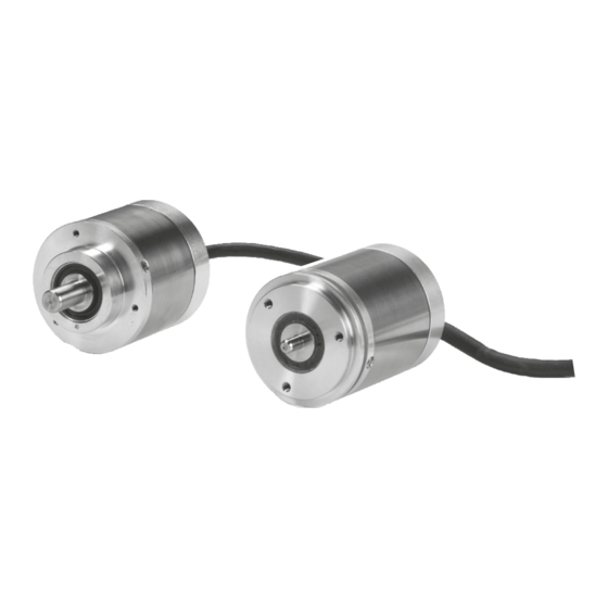
Rotary encoders for potentially explosive atmospheres (ATEX).
Drehgeber für explosionsgefährdete Bereiche (ATEX).
Capteur rotatif pour les zones à risque d'explosion (ATEX).
Encoder per ambienti potenzialmente esposivi (ATEX).
Generador rotativo de impulsos para ámbitos con peligro de
explosión (ATEX).
PTB 08 ATEX 1094 X
II 2 G Ex db IIC T 120 °C Gb
II 2 D Ex tb IIIC T 120 °C Db
Mounting Instructions
Montageanleitung
Instructions de montage
Istruzioni di montaggio
Instrucciones de montaje
ROC 413 EnDat01
ROC 413 SSI01r1
ROQ 425 EnDat01
ROQ 425 SSI07r1
WELLA1: 01J, 01A
FLANA1: 03C, 01C
12/2018
Publicidad
Tabla de contenido

Manuales relacionados para HEIDENHAIN ROC 413 EnDat01


Resumen de contenidos para HEIDENHAIN ROC 413 EnDat01
- Página 1 Mounting Instructions Montageanleitung Instructions de montage Istruzioni di montaggio Instrucciones de montaje ROC 413 EnDat01 Rotary encoders for potentially explosive atmospheres (ATEX). Drehgeber für explosionsgefährdete Bereiche (ATEX). Capteur rotatif pour les zones à risque d’explosion (ATEX). ROC 413 SSI01r1 Encoder per ambienti potenzialmente esposivi (ATEX).
-
Página 2: Tabla De Contenido
Contents Page Seite Inhalt 3 Warnings 3 Warnhinweise Sommaire 10 Items supplied 10 Lieferumfang 12 Mounting Dimensions/Assembly Indice 12 Anbaumaße/Montage Indice 20 Specifications 20 Technische Kennwerte 22 Pin Layout 22 Anschlussbelegung Page Pagina 3 Avvertenze 3 Avertissements 10 Objet de la fourniture 10 Standard di fornitura 12 Dimensioni di montaggio/Montaggio 12 Cote d'encombrement/Montage... -
Página 3: Avertissements
Posare il cavo in modo fisso (fermacavo). Fijar el cable durante el funcionamiento (descarga de tracción). Do not repair the encoder. If service is needed, send the encoder to HEIDENHAIN Service, Traunreut. Messgerät nicht reparieren. Im Servicefall an HEIDENHAIN-Service, Traunreut, senden. - Página 4 Warnings Warnhinweise Avertissements Avvertenze Advertencias Note: Mounting and commissioning is to be conducted by a qualified specialist under compliance with local safety regulations. In addition to this, the machine manufacturer or designer himself must define the other data required for final assembly (e.g. anti-rotation lock for screws required or not) for the respective application. Do not engage or disengage any connections while under power.
- Página 5 Attention: Le montage et la mise en service doivent être assurés par un personnel qualifié dans le respect des consignes de sécurité locales. D’autre part, le fabricant/constructeur de la machine doit définir d’autres données nécessaires au montage final (p.ex. sécurité frein de vis oui/non) pour l´application respective. Le connecteur ne doit être connecté...
- Página 6 Warnings Warnhinweise Avertissements Avvertenze Advertencias Fault detection signal = High: Störungssignal Signal de perturbation Segnale di malfunzionamento = Low: * Señal de avería *) The fault-detection signal is not reset until after the rotary encoder has cooled. Das Rücksetzen des Störungssignales erfolgt erst nach Abkühlung des Drehgebers. La réinitialisation du signal de perturbation ne s'effectue qu'après refroidissement du capteur rotatif.
- Página 7 Attention: If the temperature at the thermal switch (integrated in the encoder flange) exceeds 100 °C (± 5 K), the output signals remain available. A temperature at the thermal switch of greater than 110° C (± 5 K) switches off the supply voltage. Operation with position feedback is then no longer possible.
- Página 8 Warnings Warnhinweise Avertissements Avvertenze Advertencias If the cable exit is subject to possible load, mount the protective cover (Directive 2014/34/EU). Falls die Kabeldurchführung einer möglichen äußeren Belastung ausgesetzt wird, ist die Schutzkappe anzubringen. (Richtlinie 2014/34/EU). Si le passage du câble est exposé à une éventuelle charge externe, ...
- Página 9 Protective cover included in delivery Schutzkappe im Lieferumfang enthalten Capot de protection compris dans la fourniture Cappuccio di protezione incluso nello standard di fornitura La tapa de protección figura entre los elementos suministrados...
-
Página 10: Items Supplied
Items supplied Lieferumfang Contenu de la livraison Standard di fornitura Suministro Order separately: Separat bestellen: Commander séparément: Ordinare separatamente: Pedir por separado: Mounting bracket Mounting flange Montagewinkel Montageflansch Equerre de montage Bride de montage Squadretta di montaggio Flangia di montaggio Escuadra de montaje Brida de montaje ID 581296-01... - Página 11 Items supplied Lieferumfang Contenu de la livraison Standard di fornitura Suministro Order separately: Separat bestellen: Commander séparément: Ordinare separatamente: Pedir por separado: Fixing clamps (3 required) Adapter flange Spannpratzen (3 Stück nötig) Montageglocke Griffes de montage (3 pièces nécessaires) Cloche de montage Graffette (necessari 3 pezzi) Campana di montaggio Mordazas (se requieren 3 piezas)
-
Página 12: Mounting Dimensions/Assembly
Mounting Dimensions = Bearing Anbaumaße Lagerung Cote d'encombrement Roulement Dimensioni di montaggio Cuscinetto Medidas para el montaje Rodamiento 0.08 A Tolerancing ISO 8015 0.08 B ISO 2768 - m H ... - Página 13 Assembly Montage Montage Montaggio Montaje Warning: Risk of injury from rotating parts. Protect against contact! Achtung: Verletzungsgefahr durch drehende Teile. Auf Berührungsschutz achten! Attention: danger de blessures par des pièces en rotation. Prévoir une protection au contact! Attenzione: pericolo di lesioni da pezzi rotanti. Mettere protezioni per impedire il contatto! Atención: riesgo de accidente por causa de piezas en rotación.
- Página 14 Assembly Montage Montage Montaggio Montaje = Mounting possibilities Anbaumöglichkeiten Options de montage Possibilità di montaggio Posibilidades de instalación Maximum load at shaft end. Maximale Last am Wellenende. Charge maximale en bout d‘arbreit Carico massimo a fine albero. Carga máxima en el extremo del eje.
- Página 15 4 mm 5 mm 4x M4 e.g. e.g. 3x M4 z. B. z. B. 3x M4 ISO 4762 – A2 ISO 14581 – 8.8 CH T ad es. ad es. = 2.5 Nm = 2.5 Nm p.ej. p.ej.
- Página 16 Mounting Dimensions = Bearing Anbaumaße Lagerung Cote d'encombrement Roulement Dimensioni di montaggio Cuscinetto Medidas para el montaje 0.08 A Rodamiento 10±0.5 Tolerancing ISO 8015 ISO 2768 - m H ...
- Página 17 Assembly Montage Montage Montaggio Montaje Warning: Risk of injury from rotating parts. Protect against contact! Achtung: Verletzungsgefahr durch drehende Teile. Auf Berührungsschutz achten! Attention: danger de blessures par des pièces en rotation. Prévoir une protection au contact! Attenzione: pericolo di lesioni da pezzi rotanti. Mettere protezioni per impedire il contatto! Atención: riesgo de accidente por causa de piezas en rotación.
- Página 18 Assembly Montage Montage Montaggio Montaje = Mounting possibilities Anbaumöglichkeiten Options de montage 4x M4 Possibilità di montaggio Posibilidades de instalación Maximum load at shaft end. Maximale Last am Wellenende. Charge maximale en bout d‘arbreit Carico massimo a fine albero. Carga máxima en el extremo del eje.
- Página 19 3x M3 5 mm...
-
Página 20: Specifications
Specifications Technische Kennwerte Caractéristiques techniques Dati tecnici Datos técnicos 5 m m 5 m m 25 m... - Página 21 Bending radius Cables R Biegeradius Kabel R Rayon de courbure R Piegatura R Radio de curvatura R Minimum distance from sources of interference Mindestabstand von Störquellen Distance minimale avec les sources de perturbation Distanza minima dalla fonte di disturbo Distancia mínima respecto a las fuentes de interferencias...
-
Página 22: Pin Layout
Pin Layout Anschlussbelegung Affectation des plots Piedinatura Distribución del conector Sensor Sensor A– B– DATA CLOCK CLOCK DATA PIN 11 = Internal shield Connect with 0 V of the subsequent electronics Innenschirm Mit Folge-Elektronik 0V verbinden Blindage interne Relier à l’électronique consécutive 0V Schermo interno Collegare 0V con l’elettronica successiva Blindaje interno... - Página 23 The sensor line is connected inside the encoder to the supply line. Die Sensorleitung ist intern im Messgerät mit der Versorgungsleitung verbunden. La ligne de retour est reliée à la ligne d'alimentation à l'intérieur du système de mesure. La linea del sensore è collegata internamente allo strumento di misura con la linea di alimentazione. La línea de sensor está...
- Página 24 DR. JOHANNES HEIDENHAIN GmbH Dr.-Johannes-Heidenhain-Straße 5 83301 Traunreut, Germany +49 8669 31-0 +49 8669 32-5061 E-mail: info@heidenhain.de Technical support +49 8669 32-1000 Measuring systems +49 8669 31-3104 E-mail: service.ms-support@heidenhain.de +49 8669 31-3101 TNC support E-mail: service.nc-support@heidenhain.de ...