Publicidad
Enlaces rápidos
1. Tiende la tubería flexible o el tubo desde el desagüe de evaporación hasta la toma de la bomba. Cerciórese de que la tubería de la
toma se encuentre en declive, para permitir el flujo por gravedad. (Fig. 3)
2. La tubería de descarga debe ser una tubería flexible o tubos de un diámetro interno máximo de 3/18 de pulgada, para evitar un
reflujo excesivo a la unidad. Desde la unidad de agua de condensación, extienda la tubería directamente hacia arriba, a la altura
que sea necesaria. No tienda esta tubería por encima de la cabeza/GPH del modelo específico que se esté instalando. Desde esta
altura, coloque la tubería de descarga en declive ligero, hasta un punto por encima del área de drenaje. Luego, vuélvala hacia
abajo y tiéndala hasta un punto que se encuentre aproximadamente al mismo nivel del fondo de la unidad de agua de
condensación o por debajo de éste. Esto producirá un efecto de sifón, que incrementará la eficiencia de la unidad de agua de
condensación, y en la mayoría de los casos eliminará la necesidad de una válvula de retención. Si no es posible colocar en declive
la tubería de descarga, haga un purgador en forma de "U" invertida, directamente sobre la bomba, en el punto más alto.
INSTRUCCIONES DE SERVICIO
1. ¡Asegurese de que la unidad este desconectada de la fuenta de alimentacion electrica antes de intentar prestar servicio a la
unidad o quitar cualquier componente de ella!
2. Engrase el motor al comienzo de cada temporada de acondicionamiento de aire. Use aceite sin detergentes SAE No. 10 ó 20. No
lo engrase en exceso. (Fig. 4)
3. Asegúrese de que el flotador se mueva libremente. Limpie cuando sea necesario.
4. Quite la voluta y verifique que no haya obstrucciones. Limpie cuando sea necesario.
5. Limpie el tanque con agua caliente y con un jabón suave.
6. Verifique la tubería de entrada y salida. Limpie cuando sea necesario. Asegúrese de que no haya torceduras en la línea que
puedan detener el paso del líquido.
COMPROBACION
1. Conecte la electricidad.
2. Quite el conjunto del motor y la cubierta del tanque y consérvelo nivelado.
3. Pruebe el interruptor del motor, levantando su flotador con el dedo (Fig 5). El motor deberá encenderse inmediatamente antes de
que el fiador del perno del pistón entre en contacto con la guía de la varilla.
4. Pruebe el interruptor de seguridad, levantando su flotador con el dedo. El interruptor de seguridad deberá activarse, antes de que
el flotador entre en contacto con la cubierta.
5. Vuelva a colocar sobre el tanque el conjunto de la cubierta del motor y la cubierta del tanque.
La bomba es adecuada para el uso en aguas de condensación de hornos de gas. Debe tenerse cuidado de verificar que la acidez
del agua de condensación no aumente por debajo del nivel de acidez promedio de 3,4 (para evitar una bolsa de ácido) que actuaría
como una pila, causando una corrosión localizada) limpiando o enjuagando rutinaria mente el tanque con agua limpia.
PART
DESCRIPTION
NO.
1
153120
Cover, Switch
1
2
950403
Connector, Closed End
1
3
977230
Motor, 115V
1
3
977234
Motor, 115V
3
977232
Motor, 230V
3
977236
Motor, 230V
3
977242
Motor, 230V
4
154713
Safety Switch Assy
1
4
154721
Safety Switch Assy
5
951992
Lead Wire Assy
1
6
153300
Adaptor, Tubing
1
6
154715
Check Valve
7
153220
Cover, Tank
1
8
153100
Volute/Stand
1
9
153131
Impeller
1
9
153132
Impeller
10
924038
O-Ring
1
11
153110
Cover, Volute
1
12
902434
Screw
10
10
13
153502
Tank
1
14
902436
Screw
10
10
15
951556
Wiring Harness
1
15
951222
Wiring Harness
15
951836
Wiring Harness
15
951837
Wiring Harness
16
950897
Strain Relief
1
16
950957
Strain Relief
17
950997
Strain Relief
1
18
921001
Washer, Lock
2
19
153210
Bracket, Strain Relief
1
20
153537
Switch, Float Assy
1
20
153546
Switch, Float Assy
21
921059
Washer, Lock
2
22
901424
Screw
2
23
924018
O-Ring
1
24
902421
Screw
1
© Copyright 1998 Little Giant Pump Company FORM 994530 — 04/1998:
TUBERIA
1
1
1
1
1
1
1
1
1
1
1
1
1
1
1
1
1
1
1
1
1
1
1
1
1
1
1
1
1
1
1
1
1
1
1
1
1
1
1
1
1
1
1
1
1
1
1
1
1
1
1
1
1
1
10
10
10
10
1
1
1
1
1
10
9
10
10
1
1
1
1
1
1
1
1
1
1
1
1
1
1
2
2
2
2
2
1
1
1
1
1
1
1
1
1
1
2
2
2
2
2
2
2
2
2
2
1
1
1
1
1
1
1
1
1
1
Little Giant Pump Company
P. O. Box 12010
Oklahoma City, OK 73157-2010
(405) 947-2511 • Fax: (405) 947-8720
INTRODUCTION
Your Little Giant condensate pump is designed as an automatic condensate removal pump for water dripping off an air conditioner
evaporative coil. The pump is controlled by a float/switch mechanism which turns the pump on when approximately 3 1/2" of water
collects in the tank, and automatically switches off when the tank drains to approximately 2".
Read these instructions carefully. Failure to follow these instructions voids all warranty, and could result in bodily harm or property
damage. All wiring and plumbing must be permanent, and comply with local codes. Shut off electrical power at the fuse box before
servicing the pump.
The 1978 National Electrical Code, Article 680-14(a) requires ground fault circuit interrupter (GFCI) be installed in the branch cir-
cuit supplying fountain equipment, ponds, etc. See your local electrical supply dealer for various brands of GFCI devices.
WARNING - Risk of electric shock. This pump is supplied with a grounding conductor and grounding type attachment plug. To re-
duce the risk of electric shock, be certain that it is connected only to a properly grounded, grounding type receptacle.
SAFETY GUIDELINES
DO NOT USE TO PUMP FLAMMABLE OR EXPLOSIVE FLUIDS SUCH AS GASOLINE, FUEL OIL, KEROSENE, ETC. DO NOT USE
IN EXPLOSIVE ATMOSPHERES. PUMP SHOULD BE USED WITH LIQUIDS COMPATIBLE WITH PUMP COMPONENT MATERIALS.
DO NOT HANDLE THE PUMP WITH WET HANDS OR WHEN STANDING ON A WET OR DAMP SURFACE OR IN WATER. THIS PUMP
IS SUPPLIED WITH A GROUNDING CONDUCTOR AND /OR GROUNDING TYPE ATTACHMENT PLUG. TO REDUCE THE RISK OF
ELECTRICAL SHOCK, BE CERTAIN THAT IT IS CONNECTED TO A PROPERLY GROUNDED GROUNDING TYPE RECEPTACLE. IN
ANY INSTALLATIONS WHERE PROPERTY DAMAGE AND/OR PERSONAL INJURY MIGHT RESULT FROM AN INOPERATIVE OR
LEAKING PUMP DUE TO POWER OUTAGES, DISCHARGE LINE BLOCKAGE, OR ANY OTHER REASON, A BACKUP SYSTEM(S)
AND/OR ALARM SHOULD BE USED. SUPPORT PUMP AND PIPING WHEN ASSEMBLING AND WHEN INSTALLED. FAILURE TO DO
SO MAY CAUSE PIPING TO BREAK, PUMP TO FAIL, MOTOR BEARING FAILURES ETC.
INSTALLATION
1. Carefully unpack the pump. Remove the cover assembly from the tank and remove all packing from around floats. Check each
float assembly for free movement. Place cover assembly on tank.
2. Mount the pump. There are two vertical mounting surfaces (as shown in Fig. 1) on one side of the tank to mount on side of air condi-
tioning unit, or nearby wall. Mounting holes can be drilled in this surface, but should
not exceed one inch from the top of the tank to prevent possible spillage of water.
ELECTRICAL CONNECTIONS
1. Shut off electrical power at fuse box before making any connections. All wiring must
comply with local codes.
2. Line voltage-connect the power cord to line voltage specified on motor and name-
plate. Power cord must be connected to a constant source of power (not a fan or
other device that runs intermittently). If power cord does not have a plug, wiring is as
follows: green (or green/yellow)–ground. Black (or brown)–line. White (or blue).
3. Safety Switch-the safety overflow switch should be connected to a Class II low volt-
age circuit. Typical hook-up of 'NC' circuits would be: N.O. When water rises, circuit
opens to turn off heating or cooling equipment. N.C. When water rises, circuit closes
to activate a bell or alarm.
4. If fused type plug is used on 230v units, a 3.0 amp fuse is recommended.
PIPING
1. Run flexible tubing or pipe from evaporator drain into pump inlet. Be sure inlet pip-
ing is sloped downward to allow gravity flow (Fig 3).
2. The outlet piping should be flexible tubing or pipe (3/8" I.D. maximum to prevent
excessive flow back to unit). From condensate unit, extend discharge piping
straight up as high as necessary. Do not extend this line above the head/GPH of
the particular model being installed. From this high point, slope discharge line
down slightly to a point above drain area; then turn down and extend to a point
below or approximately level with the bottom of the condensate unit. This will give
a syphoning effect which will improve efficiency of the condensate unit and will, in
most cases, eliminate the need for a check valve. If it is not possible to slope dis-
charge line down, make an inverted "U" trap directly above the pump at the high-
est point.
SERVICE INSTRUCTIONS
1. MAKE CERTAIN THE UNIT IS DISCONNECTED FROM THE POWER SOURCE
BEFORE ATTEMPTING TO SERVICE OR REMOVE ANY COMPONENT!
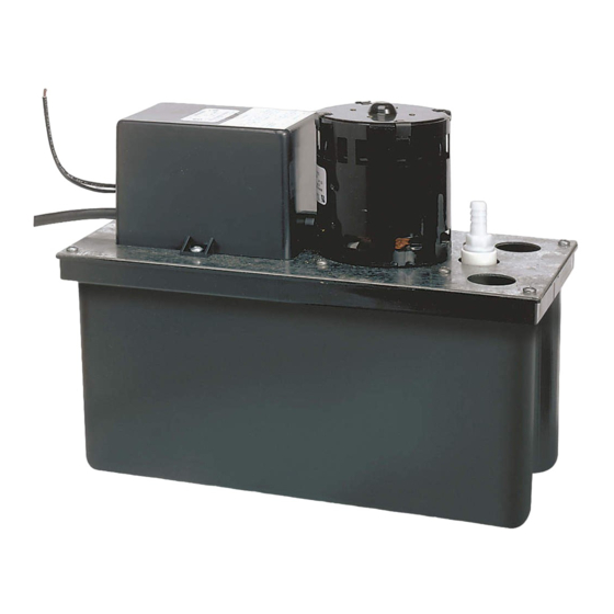
VCL-14ULS
VCL-24UL
VCL-24ULS
VCL-24S
Fig. 1
Check floats for
free
movement.
S'assurer que les
flotteurs ne
bougent pas.
Verifique el
funcionamient
o correcto de
los flotadores.
Mounting
Surface
Surface de
montage
Superficie de
montaje
Fig. 2
Publicidad

Manuales relacionados para Little Giant VCL-14ULS


Resumen de contenidos para Little Giant VCL-14ULS
- Página 1 INTRODUCTION Your Little Giant condensate pump is designed as an automatic condensate removal pump for water dripping off an air conditioner 1. ¡Asegurese de que la unidad este desconectada de la fuenta de alimentacion electrica antes de intentar prestar servicio a la evaporative coil.
- Página 2 2. Enlever le couvercle qui couvre l’ensemble moteur, réservoir et le supporter de niveau. Votre pompe à condensats Little Giant est conçue comme une unité automatique d’évacuation des condensats. Elle évacue l’eau 3. Tester le commutateur de moteur en levant le commutateur de moteur du flotteur avec le doigt (Fig. 5). Le moteur doit se mettre en condensée s’égouttant de la volute de l’évaporateur d’un système de climatisation.