Tabla de contenido
Publicidad
Idiomas disponibles
Idiomas disponibles
Enlaces rápidos
Franklin Electric Co., Inc.
P . O. Box 12010
Oklahoma City, OK 73157-2010
888.956.0000 • Fax: 405.947.8720
www.LittleGiantWater.com
CustomerService-WTS@fele.com
INTRODUCTION
EN
This instruction sheet provides you with the information required
to safely own and operate your Little Giant product. Retain these
instructions for future reference.
The Little Giant product you have purchased is of the highest
quality workmanship and material, and has been engineered to
give you long and reliable service. Little Giant products are care-
fully tested, inspected, and packaged to ensure safe delivery and
operation. Please examine your item(s) carefully to ensure that
no damage occurred during shipment. If damage has occurred,
please contact the place of purchase. They will assist you in
replacement or repair, if required.
READ
THESE
INSTRUCTIONS
ATTEMPTING
TO
INSTALL,
YOUR LITTLE GIANT PRODUCT. KNOW THE PRODUCT'S
APPLICATION, LIMITATIONS, AND POTENTIAL HAZARDS.
PROTECT YOURSELF AND OTHERS BY OBSERVING ALL
SAFETY INFORMATION. FAILURE TO COMPLY WITH THESE
INSTRUCTIONS COULD RESULT IN PERSONAL INJURY AND/
OR PROPERTY DAMAGE!
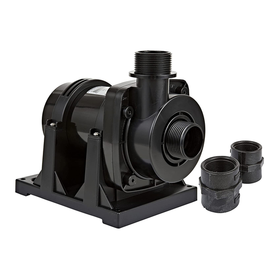
DESCRIPTION
The FP series Flex Pumps provide circulating, oxygenated water
to features such as ponds, fountains, displays, waterfalls, and
filter systems.
SAFETY GUIDELINES
WARNING: RISK OF ELECTRICAL SHOCK. PLEASE OBSERVE
THE FOLLOWING SAFETY GUIDELINES.
WARNING: This pump has not been investigated for use in swim-
ming pools.
This pump uses a grounding conductor and a grounding-type
attachment plug. To reduce the risk of electrical shock, connect the
pump only to a properly grounded, grounding-type receptacle.
Employ a qualified, licensed electrician to provide electrical
power.
Min. 6.5 ft. (2m)
FP SERIES FLEX PUMP •
POMPE FLEX DE
SÉRIE FP • SERIE FP
BOMBA FLEXIBLE
CAREFULLY
OPERATE,
OR
Min. 10 in. (25cm)
FIGURE 1
Check product label for proper voltage required. Do not connect
to voltage other than that shown.
To comply with the National Electric Code (NEC) and to reduce
the risk of electric shock, connect the pump only to an outlet pro-
tected by a ground fault circuit interrupter (GFCI).
Check the power cord regularly to ensure that it is in good condi-
tion, with no nicks or cuts.
Do not lift the pump by its power cord.
Do not let the pump freeze during colder temperatures. This can
cause cracking or distortion that will damage the pump. See the
MAINTENANCE section for storage instructions.
Do not operate the pump dry. This will cause the pump to become
extremely hot, causing burns if touched and/or damage to the
pump.
Do not use to pump water hotter than 95°F (35°C).
WARNING: Ensure that the installation conforms with all local and
state electric codes.
NOTE: The pump has thermal overload protection. If it becomes
BEFORE
overheated it will shut off. See the Troubleshooting section to
SERVICE
restart.
In-Water (Submersible) Installation
Refer to Figure 1, Figure 2, and the following steps to configure
the pump for in-water (submersible) use:
1. Locate the connection box in a dry area at least 6-1/2 feet (2
meters) from the edge of the water.
2. Place the pump into the water on a flat surface, ensuring that
the pump is completely submersed and that the volute is filled
with water.
CAUTION: If the surface is dirt or sand, place the pump on a
flat object such as a brick or stone to prevent clogging. For
best results, place the pump into a skimmer.
CAUTION: Ensure that the water level does not go below
25cm (FP1, FP2, and FP3) or 30cm (FP6 and FP9).
3. FP1, FP2, and FP3 ONLY: The discharge can be configured
to point up or to the side, depending on the application. To
redirect the discharge, loosen the four clip screws (1), turn the
motor housing (9) until the discharge is in the desired position,
and tighten the screws.
4. Make all necessary intake and discharge connections.
NOTE: Use a pre-filter on the intake for added protection from
clogging.
Min. 6.5 ft. (2m)
INSTALLATION AND OPERATION
Min. 10 in. (25cm)
FIGURE 2
1
Publicidad
Tabla de contenido

Manuales relacionados para Little Giant FP Serie


Resumen de contenidos para Little Giant FP Serie
- Página 1 This instruction sheet provides you with the information required Do not operate the pump dry. This will cause the pump to become to safely own and operate your Little Giant product. Retain these extremely hot, causing burns if touched and/or damage to the instructions for future reference.
- Página 2 For pin (14) fits into the hole (not shown) in the volute. easier installation, use Little Giant installation kit 566259 and leaf basket 566106 (optional). 12. Install the two clips (2) and secure them using the four clip screws (1).
- Página 3 9. Inspect all parts. Replace any that are damaged or excessively CLEANING THE FP6 AND FP9 (FIGURE 6): worn. (Refer to the Replacement Parts table.) 1. Disconnect the pump from power. 10. Install the o-ring (10) onto the connection flange (12). 2.
-
Página 4: Directives De Sécurité
Voir la section tard. Dépannage pour redémarrer la pompe. Le produit Little Giant que vous avez acheté a été soigneusement Installation dans un plan d’eau (submersible) fabriqué avec des matériaux de la plus haute qualité et a été... - Página 5 Pour faciliter l’installation, 1. Débrancher la pompe de sa source d’alimentation. utiliser la trousse d’installation 566259 de Little Giant et le 2. Enlever les quatre vis à pince (1) et les deux pinces (2). panier à feuilles 566106 (en option).
-
Página 6: Introducción
Esta hoja de instrucciones le proporciona la información requerida todas las normas eléctricas locales y estatales. para tener y operar de forma segura su producto Little Giant. NOTA: La bomba cuenta con protección contra sobrecarga tér- Guarde las instrucciones para referencia futura. -
Página 7: Mantenimiento
566259 y la cesta para canal colector (4) y el conjunto de brida de unión (recuadro) hojas 566106 (opcional) de Little Giant. al alojamiento del motor (9). 5. Llene de agua la manguera de entrada y el canal colector. -
Página 8: Almacenamiento
7. Instale el anillo tórico en el alojamiento del motor. 8. Deslice con cuidado el conjunto de rotor en el alojamiento del motor, asegurándose de que los dos agujeros (5) de la placa queden alineados con las dos clavijas (8) del alojamiento. 9. - Página 9 TROUBLESHOOTING • INFORMATION SUR LA RELÈVE DES DÉRANGEMENTS • INFORMACION DE INVESTIGACION DE AVERIAS PROBLEM • FONCTIONNEMENT PROBABLE CAUSES • CAUSES PROBABLES CORRECTIVE ACTION • SOLUTIONS DÉFECTEUX • PROBLEMA • CAUSAS PROBABLES • SOLUCION The pump does not run. • La pompe Power cord unplugged.
-
Página 10: Garantie Limitée
La présente garantit que votre pompe Little Giant est en parfaite the option of Little Giant as the sole remedy of buyer. For our cus- condition à sa sortie de l’usine. La pompe est garantie contre tout tomers in the CONTINENTAL UNITED STATES: Please return the défaut de matériau ou de fabrication pendant une période de 60... -
Página 11: Garantia Limitada
Little Giant o avisarle a la fábrica de los detalles del problema para que la fábrica disponga de las acciones necesarias y resuelva el reclamo de la garantía. - Página 12 ..... . .1-888-572-9933 Para la ayuda técnica, por favor póngase en contacto ..1-888-956-0000 www.LittleGiantPump.com CustomerService-WTS@fele.com Form 998664 - 01/23/2009 © 2009 Franklin Electric Co., Inc. Little Giant® is a registered trademark of Franklin Electric Co., Inc.