Publicidad
Idiomas disponibles
Idiomas disponibles
Enlaces rápidos
English
P/N 030-781 b
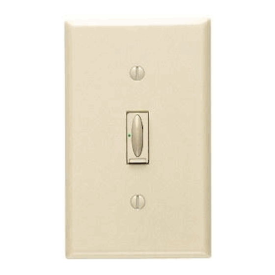
TM
Electronic Switch
FA-S6A 120 V~ 60 Hz 6 A maximum
The Electronic Switch is rated for lighting and fan loads only.
Important Notes
Please read before installing.
1. Caution: To avoid overheating and possible damage to other equipment, do not use to
control receptacles or transformer supplied appliances.
2. Install in accordance with all national and local electrical codes.
3. This switch requires a neutral wire for operation. If no neutral wire is present,
contact a licensed electrician for installation.
4. When no "grounding means" exist within the wallbox then the NEC
®
allows a dimmer without a grounding connection to be installed as a replacement, as
long as a plastic, noncombustible wallplate is used. For this type of installation, cap or
remove the green ground wire on the dimmer and use an appropriate wallplate such as
Lutron's Fassada
series wallplates.
TM
5. Do not paint front or back of Electronic Switch.
6. Do not use where total load is greater than rating indicated in Derating Chart below.
7. Do not use where total lighting load is less than 5 watts.
8. Operate between 32 °F (0 °C) and 104 °F (40 °C).
9. It is normal for the Electronic Switch to feel warm to the touch during operation.
10. Recommended wallbox depth is 2 1/2" minimum.
11. When controlling a combined fan and light load, the total load may not exceed 3 amps.
12. Clean Electronic Switch with a soft damp cloth only . Do not use any chemical
cleaners.
Multigang Installations
When combining controls in the same wallbox, remove all inner side sections prior to
wiring (see below). Using pliers, bend side sections up and down until they break off.
Repeat for each side section to be removed. Refer to the Derating Chart below for
maximum Electronic Switch capacity. Please note that the Electronic Switch is not derated
for fans loads, but when controlling a combined fan and light load, the total load may not
exceed 3 amps.
Do Not Remove
Breaking Side
Sections
Each Control Has
Middle Control Has
Inside Section
Two Side Sections
Removed
Derating Chart
Maximum Load
No Sides
1 Side
Type of Load
Removed
Removed
Incandescent/Halogen
750 W
600 W
Magnetic low-voltage
750 VA/550 W
600 VA/450 W
Electronic low-voltage
750 W
600 W
Fluorescent*
6 A
5 A
General Purpose Fan
3 A
3 A
* The Faedra
Electronic Switch is UL listed for use with the following fluorescent ballasts.
TM
Manufacturer
Model Number
Advance Transformer Co.
REL-2P32-RH-TP
Magnetek
B232I120RH
GE Lighting/Motorola Lighting Inc.
G2-RN-T8-1LL-120
Valmont Electric
E232PI120G01
Sylvania
QT2X32/120IS
Please call the Lutron Technical Support Center at +1-800-523-9466 for an up-to-date listing.
Installation
1
Turning OFF power.
• Turn power OFF at circuit breaker (or remove fuse).
2
Removing wallplate and switch.
• Remove the wallplate and switch mounting screws.
• Carefully remove switch from wall (do not remove wires).
Caution: Verify power to
each switch is OFF before
2002, Article 404-9
proceeding.
3
Disconnecting switch wires.
• Carefully disconnect the switch wires.
OR
Backwired:
Screw Terminals:
Insert screwdriver.
Turn screws to loosen.
Pull wire out.
If a neutral wire is not present, contact a licensed electrician for
installation.
Important Wiring Information
Outside
Sections
When making wire connections, follow the recommended strip lengths and wire combinations
for the supplied wire connectors. Note: Wire connectors provided are suitable for copper wire
only. For aluminum wire, consult an electrician.
Recommended Strip Lengths:
Strip insulation 1/2" (13 mm) for 10, 12 or 14 AWG
wire
Important Wiring Information
Removed
1/2" (13 mm)
Strip insulation 5/8" (16 mm) for 16 or 18 AWG wire
5/8" (16 mm)
Use provided wire connectors to join one or two 12
2 Sides
or 14 AWG supply wires with one 10, 12, 14, 16, or
Removed
18 AWG control wire.
450 W
Operation
450 VA/300 W
450 W
Basic Operation
3.5 A
Tap Button Options
3 A
• Tap once when unit is OFF - Controlled
load turns ON.
• Tap once when unit is ON - Controlled
load turns OFF.
LED
- Glows brightly when the Electronic
Switch is ON or glows softly as a night light
when Electronic Switch is OFF.
IMPORTANT NOTICE:
FASS
- Front Accessible Service Switch - For routine lamp replacement,
TM
power may be conveniently removed by pulling the FASS
any procedure other than routine lamp replacement, power must be
disconnected at the main electrical panel.
4
Wiring the Electronic Switch.
• For installations involving more than one control in a wallbox, refer
to Multigang Installations before beginning.
Yellow
White
• Connect the green ground wire of the
Electronic Switch to the green or bare
copper ground wire in the wallbox (if none
exists, see Important Note 4).
• Connect the black wire of the Electronic
Switch to the live (hot) wire coming from
the distribution panel.
• Connect the yellow wire of the Electronic
Switch to the wire leading to the load.
Black
Ground
• Connect the white wire of the Electronic
Green
Switch to neutral. If a neutral wire is not
present, contact a licensed electrician
for installation.
Reference Wiring Diagram:
Electronic Switch
Live/Hot
Black
Yellow
Green
120 V~
60 Hz
White
Ground
Neutral
Wallbox
5
Mounting switch to wallbox.
• Form wires carefully into the wallbox, mount and align Electronic
Switch.
• Replace wallplate.
Caution: Do not
overtighten mounting
screws.
Start screws.
Twist wire connector tight.
Be sure no bare wire is
exposed.
6
Turning ON power.
• Turn power ON at circuit breaker (or replace fuse).
Advanced Feature
Delay to OFF -
Press and hold
the tap button until the LED begins to
flash to activate Delay to OFF. When
button is released, the controlled load
will automatically turn OFF after 70
seconds.
switch out. For
TM
To Change Tap Button (Optional)
1
Turn power OFF at circuit breaker or remove
fuse.
2
Unlock the tap button by sliding the release
clip to the left.
3
Remove the tap button from the Electronic
Switch. (To aid in the removal, firmly place a
piece of tape on the tap button, gently pull on
the tape to begin sliding the tap button out of
the Electronic Switch until it can be grasped
by your thumb and index finger.)
4
Insert new tap button into Electronic Switch.
If the black and yellow
wires are reversed, the
unit will not operate. It
may be necessary to
swap the connections to
Load
ensure that the yellow
5
Lock the new tap button by sliding the
wire is connected to the
release clip to the right.
load.
6
Turn power ON at circuit breaker or replace
fuse.
Troubleshooting
Symptom
Load does not turn ON, but
LED on Electronic Switch is
ON.
Align Electronic
Load does not turn ON, and
Switch and tighten
screws.
LED on Electronic Switch is
OFF.
Ensure FASS
TM
switch is pushed in.
Tap button cannot be
removed.
Technical Assistance
?
If you have questions concerning the installation or operation of this product, call the
Lutron Technical Support Center . Please provide exact model number when calling.
U.S.A. and Canada (24 hrs/7days)
+1-800-523-9466
Other countries 8am – 8pm ET
+1-610-282-3800
Limited Warranty
Lutron will, at its option, repair or replace any unit that is defective in materials or manufacture within one
year after purchase. For warranty service, return unit to place of purchase or mail to Lutron at 7200 Suter
Rd., Coopersburg, PA 18036-1299, postage pre-paid.
THIS WARRANTY IS IN LIEU OF ALL OTHER EXPRESS WARRANTIES, AND THE IMPLIED WARRANTY
OF MERCHANTABILITY IS LIMITED TO ONE YEAR FROM PURCHASE. THIS WARRANTY DOES NOT
COVER THE COST OF INSTALLATION, REMOVAL OR REINSTALLATION, OR DAMAGE RESULTING
FROM MISUSE, ABUSE, OR DAMAGE FROM IMPROPER WIRING OR INSTALLATION. THIS WARRANTY
DOES NOT COVER INCIDENTAL OR CONSEQUENTIAL DAMAGES. LUTRON'S LIABILITY ON ANY
CLAIM FOR DAMAGES ARISING OUT OF OR IN CONNECTION WITH THE MANUFACTURE, SALE,
INSTALLATION, DELIVERY, OR USE OF THE UNIT SHALL NEVER EXCEED THE PURCHASE PRICE
OF THE UNIT.
This warranty gives you specific legal rights, and you may have other rights which vary from state to state.
Some states do not allow the exclusion or limitation of incidental or consequential damages, or limitation on
how long an implied warranty may last, so the above limitations may not apply to you.
This product may be covered under the following U.S. patents: D472,221; D477,289; D477,577; D478,054
and corresponding foreign patents. U.S. and foreign patents pending. Lutron is a registered trademark and
faedra and FASS are trademarks of Lutron Electronics Co., Inc. NEC is a registered trademark of the
National Fire Protection Association, Quincy, Massachusetts.
© 2005 Lutron Electronics Co., Inc.
Lutron Electronics Co., Inc.
7200 Suter Road
Coopersburg, PA 18036-1299, U.S.A.
Made and printed in the U.S.A. 1/05 P/N 030-781 Rev. B
Possible Cause
• Lamps are burned out.
• Electronic Switch is not properly wired.
• Load is not properly installed.
• Electronic Switch is not properly wired, yellow and
black wires may be reversed.
• Front Accessible Service Switch (FASS
) on the
TM
Electronic Switch is pulled out.
• Breaker is OFF or tripped.
• Release clip has not been entirely pushed to the left.
Fax +1-610-282-3090
http://www.lutron.com
Publicidad

Manuales relacionados para Lutron faedra FA-S6A


Resumen de contenidos para Lutron faedra FA-S6A
- Página 1 • Tap once when unit is OFF - Controlled the tap button until the LED begins to Lutron will, at its option, repair or replace any unit that is defective in materials or manufacture within one load turns ON. flash to activate Delay to OFF. When year after purchase.
- Página 2 Por favor llame al Centro de Apoyo Técnico de Lutron al +1-800-523-9466 para obtener una lista comercial registrada, y faedra y FASS son marcas comerciales de Lutron Electronics Co., Inc. NEC es una marca de las lámparas, la energía se debe desconectar en el tablero eléctrico principal.
- Página 3 électrique peut facilement être coupée en tirant l’interrupteur FASS vers l’extérieur. Pour toute déposée, et faedra et FASS sont des marques de commerce de Lutron Electronics Co., Inc. NEC est une marque de commerce de National Fire Protection Association, Quincy, Massachusetts.