Tabla de contenido
Publicidad
Idiomas disponibles
Idiomas disponibles
Enlaces rápidos
Energi Savr Node
Please read this guide before installing.
Contents
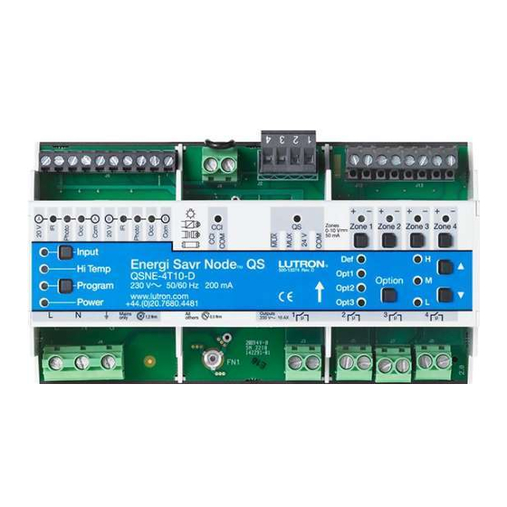
Ratings and Model number overview ....................................1
Product overview..................................................................2
Wiring overview....................................................................2
Mounting ..............................................................................3
Control power wiring ............................................................3
Load wiring ..........................................................................4
Input group wiring ................................................................6
PELV Emergency Contact Closure Input .................................6
QS link wiring .......................................................................7
System Programming Connection .........................................9
Sample Application .............................................................10
Out of Box Functionality ......................................................10
Normal Operation ...............................................................11
QS link input(s) setup .........................................................11
Troubleshooting ..................................................................11
Warranty ............................................................................12
Contact information ............................................................12
System Example
IR Transmitter
Wired IR Receiver
Wired Daylight Sensor
Wired Occupancy
Sensor
One input group shown;
connections available for
two input groups
Energi Savr Node
QS unit
220-240 V~
Control Power
Contact Closure Input
Note: Multiple QSMs can be
added to increase the number
of wireless inputs and
wireless controllers.
Energi Savr Node
QS for 0-10 V / Switching Installation Guide
TM
QS for 0-10 V / Switching
TM
Page
4 switched outputs, 10 AX each (zones 1-4)
4 0-10 V outputs (zones 1-4)
2
(model QSNE-4T10-D only)
Energi Savr Node
Programming
Interface
™
QS Link
Pico
wireless
Radio Powr Savr
®
TM
controller (up
Occupancy Sensor
to 10 per QSM)
(up to 10 per QSM)
Pico
®
Radio Powr Savr
TM
Daylight Sensor
2
(up to 10 per QSM)
|
Installation Guide
Ratings
Control Power: 220-240 V ~ 50/60 Hz 200 mA
Output: 0-10 V: 50 mA source/sink per zone (QSNE-4T10-D only)
Switching: 220-240 V ~ 10 AX per output
Operating environment: 0 ˚C to 40 ˚C ambient room temperature
Maximum humidity: 90% non-condensing
Thermal dissipation: 40 BTU/hr
Calibration point maximum: 65 ˚C
QS link: 24 V- 14 PDU (Power Draw Units) 460 mA
Input Groups: 20 V - 65 mA per group
Standards: IEC/EN 60669-2-1
Load types: Incandescent, fluorescent, magnetic low voltage,
electronic low voltage
Model number overview
QSNE-4T10-D (Energi Savr Node
QSNE-4S10-D (Energi Savr Node
QSNE: Energi Savr Node
4T: 4 output zones, switching / 0-10 V fixture controller
4S: 4 output zones, switching only
10: 10 AX per output
D: DIN rail compatible
QS
TM
seeTouch
QS
®
Wallstation
Quantum
Panel
Energi Savr
Node
QS
TM
Wireless
Communication
Wired
Wired
Daylight
Occupancy
Sensors
1, 2
Sensors
Notes:
1 Up to four wired inputs total (of any type).
2 See "Daylight Sensors" in "Specifications" section
for sensor count options.
QS for 0-10 V)
TM
QS for switching)
TM
QS
TM
QS
Contact
®
Closure
GRAFIK Eye
®
Interface
QS Unit
QS Power
QS Sensor
Supply
Module (QSM)
IR Transmitter
Wired
IR Receivers
1
1
Up to 100
total QS
devices
Lutron
1
|
®
Publicidad
Capítulos
Tabla de contenido

Manuales relacionados para Lutron Energi Savr Node QS


Resumen de contenidos para Lutron Energi Savr Node QS
-
Página 1: Tabla De Contenido
(up to 10 per QSM) Notes: 1 Up to four wired inputs total (of any type). 2 See "Daylight Sensors" in "Specifications" section for sensor count options. Energi Savr Node QS for 0-10 V / Switching Installation Guide Lutron ®... -
Página 2: Product Overview
The diagram on the previous page shows a typical system topology. • All lighting loads are powered through the ESN QS unit. • The ESN QS unit is limited to: – 2 Lutron wired daylight sensors (models: EC-DIR-WH) ® – 2 Lutron wired occupancy sensors (models: Lutron LOS series) ® ® – 2 Lutron wired infrared (IR) receivers (models: EC-DIR-WH, EC-IR-WH) ®... -
Página 3: Control Power Wiring
Note: If additional wiring space is required, the ESN QS unit 7. Close front cover of panel. can be removed from the DIN rail while wiring. Follow the instructions from step 1 for details. Energi Savr Node QS for 0-10 V / Switching Installation Guide Lutron ®... - Página 4 • Two (2) 1,0 mm to 4,0 mm non-SELV/PELV circuits to 0-10 V zones 1-4. Do not • Strip length: 8,0 mm mix SELV/PELV circuits and non-SELV/PELV circuits. • Torque: 0,79 N • • Follow all national and local codes for separation requirements. Lutron Energi Savr Node QS for 0-10 V / Switching Installation Guide ®...
-
Página 5: Load Wiring
• Two (2) 1,0 mm to 4,0 mm non-SELV/PELV circuits to 0-10 V zones 1-4. Do not • Strip length: 8,0 mm mix SELV/PELV circuits and non-SELV/PELV circuits. • Torque: 0,79 N • • Follow all national and local codes for separation requirements. Energi Savr Node QS for 0-10 V / Switching Installation Guide Lutron ®... -
Página 6: Input Group Wiring
If no Emergency contact input is required, please CCI – EMERGENCY leave the wire jumper in the CCI terminals. Contact Closure Wiring: • 1,0 mm to 2,5 mm • Strip length: 8,0 mm • Torque: 0,79 N • Lutron Energi Savr Node QS for 0-10 V / Switching Installation Guide ®... -
Página 7: Qs Link Wiring
The total distance of the QS link wiring must not exceed 610 m. QS Link Wiring Available from Distance Wire Gauge Lutron in one cable: Power (terminals 1 and 2): 1 pair 1,0 mm Less than 152,4 m GRX-CBL-346S Data (terminals 3 and 4):... - Página 8 * Terminal 2 (+24 V) should NEVER be connected between devices that supply PDUs. ** For QS Link power supply wiring connection details, refer to the installation instructions for the specific power supply model being used. Lutron Energi Savr Node QS for 0-10 V / Switching Installation Guide...
-
Página 9: System Programming Connection
• Wireless router may be removed for normal operation. • Ethernet connection may be made via an an ESN Programming Interface or an ESN QS unit with integral Ethernet jack. • Lutron recommends that an ESN Programming Interface (or ESN QS unit with Ethernet jack) be wired to an Ethernet jack in the space for ease of access and proximity to power for the wireless router. • Works with any standard wireless router that supports multicast packets. -
Página 10: Sample Application
(closed) and off when in the unoccupied state 1, 5-16 100% (open). Daylight Sensors (Photo) • When used in conjunction with a Lutron occupancy sensor, ® • Scene Off will turn all the lights off. corresponding zones will turn on when light sensed by daylight sensor falls below the factory preset level (if occupancy sensor Contact Closure Input (CCI) indicates that area is occupied). -
Página 11: Normal Operation
Remote input Note: For more advanced programming information, refer to the Normal operation/Contact Continuous On online Programming Guide at: Closed/Jumpered (Contact http://www.lutron.com/InstallationInstructions/230Vesn Emergency Mode/Contact Closure Input) Rapid flash Open/Jumper missing 1 flash per second Device is in Program Mode Program... -
Página 12: Warranty
(at the sole discretion of Lutron EA), and shall be effective only if the defective unit is shipped to Lutron EA postage prepaid within 24 months of purchase of the unit. Repair or replacement of the unit does not affect the expiry date of the warranty. -
Página 13: Ejemplo De Sistema
1 Un total de hasta cuatro sensores con cables (de cualquier tipo) 2 Para las opciones de recuento de sensores, consulte “Sensores de luz natural” en la sección “Especificaciones”. Energi Savr Node QS de 0-10 V / Guía de instalación de conmutación Lutron ®... -
Página 14: Perspectiva General De Productos
QS. El esquema de la página anterior muestra una topología de sistema tipo. • Todas las cargas de iluminación se alimentan a través de la unidad ESN QS. • La unidad ESN QS cuenta con conexiones físicas para: – 2 sensores de luz natural Lutron con cables (modelos: EC-DIR-WH) ® – 2 sensores de presencia Lutron... -
Página 15: Montaje
QS del carril DIN durante el cableado. Conecte el cable de tierra . Para más información, siga las instrucciones desde el paso 1. Energi Savr Node QS de 0-10 V / Guía de instalación de conmutación Lutron ®... -
Página 16: Cableado De Carga
SELV/PELV a las zonas 1-4 de 0-10 V. • Par: 0,79 N • No mezcle circuitos SELV/PELV y no SELV/PELV. • Siga todos los códigos eléctricos nacionales y locales para los requisitos de separación. Lutron Energi Savr Node QS de 0-10 V / Guía de instalación de conmutación ®... - Página 17 SELV/PELV a las zonas 1-4 de 0-10 V. • Par: 0,79 N • No mezcle circuitos SELV/PELV y no SELV/PELV. • Siga todos los códigos eléctricos nacionales y locales para los requisitos de separación. Energi Savr Node QS de 0-10 V / Guía de instalación de conmutación Lutron ®...
-
Página 18: Cableado De Grupo De Entrada
CCI se deja abierta. Si no se requiere ninguna • 1,0 mm a 2,5 mm entrada de contacto de emergencia, deje el cable puente en los • Longitud de pelado de los terminales CCI. cables: 8,0 mm • Par: 0,79 N • Lutron Energi Savr Node QS de 0-10 V / Guía de instalación de conmutación ®... -
Página 19: Cableado De Enlace Qs
PELV con el cableado de línea/ alimentación. La distancia total del cableado de enlace QS no será superior a 610 m. Distancia de Lutron puede cableado de suministrarlo en un enlace QS Sección de cable cable: Alimentación (terminales... - Página 20 ** Para los detalles de conexión del cableado de las fuentes de alimentación QS, consulte las instrucciones de instalación para el modelo específico de fuente de alimentación que se esté utilizando. Lutron Energi Savr Node QS de 0-10 V / Guía de instalación de conmutación...
-
Página 21: Conexión De Programación Del Sistema
• Puede retirarse el router inalámbrico para el funcionamiento normal. • La conexión Ethernet puede hacerse a través de una interfaz de programación ESN o una unidad ESN QS con clavija Ethernet integrada. • Lutron recomienda la conexión de una interfaz de programación ESN (o unidad ESN QS con clavija Ethernet) a una clavija Ethernet del espacio para facilitar el acceso y por razones de proximidad a la alimentación para el router inalámbrico. • Funciona con cualquier router inalámbrico estándar compatible con paquetes multicast. • Un Apple iPod touch o iPhone pueden programar todas las unidades ESN QS conectadas a una unidad de programación ESN a través del enlace QS (excepto si forma parte de un sistema Quantum ®... -
Página 22: Aplicación De Muestra
Sensores de luz natural (Photo) 1, 5-16 100% • Cuando se utilizan junto con un sensor de presencia Lutron ® las zonas correspondientes se encenderán cuando la luz detectada por el sensor de luz natural sea inferior al nivel predefinido de fábrica (si el sensor de presencia detecta... -
Página 23: Funcionamiento Normal
Nota: Para más información sobre programación avanzada, Modo de emergencia/Contacto de contacto Parpadeo rápido consulte la Guía de programación online en: abierto/Falta puente http://www.lutron.com/InstallationInstructions/230Vesn El dispositivo está en modo de 1 destello por segundo programa Programa El dispositivo está en modo de... -
Página 24: Garantía
(a opción exclusiva de Lutron EA) y serán de aplicación sólo cuando la unidad se envíe a Lutron EA a portes pagados en el plazo de 24 meses desde la fecha de compra de la unidad. La reparación o la sustitución de la unidad no afectarán a la fecha de vencimiento de la garantía. -
Página 25: Caractéristiques Nominales
1 Jusqu’à quatre capteurs filaires au total (de tout type) 2 Voir « Capteurs de lumière du jour » dans la section « Spécifications » pour les options de décompte des capteurs. Guide d’installation Energi Savr Node QS pour 0-10 V/commutation Lutron ®... -
Página 26: Aperçu Du Produit
10 AX par zone. Un système ESN QS se compose d’une unité ESN QS, de charges d’éclairage, d’entrées, de commandes murales et de dispositifs d’interface QS. Le schéma de la page précédente illustre une topologie typique de système. • Toutes les charges d’éclairage sont alimentées par l’unité ESN QS. • L’unité ESN QS est dotée de connexions physiques pour : – 2 capteurs de lumière filaires Lutron (modèle EC-DIR-WH) ® – 2 détecteurs de présence filaires Lutron (modèles : série Lutron... - Página 27 • L’unité ESN QS est reliée à la terre par la borne . Fixer le fil Suivre les instructions à partir de l’étape 1 pour plus de détails. de terre. Guide d’installation Energi Savr Node QS pour 0-10 V/commutation Lutron ®...
- Página 28 PELV aux zones 0-10 V 1 à 4. ne pas mélanger les • Couple de serrage : 0,79 N circuits SELV/PELV et les circuits non SELV/PELV. • • Respecter toutes les normes locales et nationales pour connaître les exigences de séparation. Lutron Guide d’installation Energi Savr Node QS pour 0-10 V/commutation ®...
-
Página 29: Câblage Des Charges
• Couple de serrage : 0,79 N • PELV aux zones 0-10 V 1 à 4. ne pas mélanger les circuits SELV/PELV et les circuits non SELV/PELV. • Respecter toutes les normes locales et nationales pour connaître les exigences de séparation. Guide d’installation Energi Savr Node QS pour 0-10 V/commutation Lutron ®... -
Página 30: Entrée D'urgence À Contact Sec Pelv
CCI – URGENCE n’est nécessaire, laisser le cavalier dans les bornes CCI. Câblage des contacts à fermeture : • 1,0 mm à 2,5 mm • Longueur à dénuder : 8,0 mm • Couple de serrage : 0,79 N • Lutron Guide d’installation Energi Savr Node QS pour 0-10 V/commutation ®... - Página 31 La distance totale du câblage du bus QS ne doit pas dépasser 610 m. Distance Disponible chez de câblage Lutron en un seul du bus QS Section de câble câble : Alimentation (bornes 1 et 2) : 1 paire de 1,0 mm (1) COM Inférieure...
-
Página 32: Câblage Du Bus Qs
* La borne 2 (+24 V) ne doit JAMAIS être raccordée entre les dispositifs qui alimentent les PDU. ** Pour le raccordement du câblage d’alimentation du bus QS, consulter les instructions d’installation du modèle d’alimentation spécifique utilisé. Lutron Guide d’installation Energi Savr Node QS pour 0-10 V/commutation... -
Página 33: Connexion De Programmation Du Système
QS pour 0-10 V / Commutation Guide d’installation Câblage : connexion de programmation du système Unité ESN QS Types de câble : 1 Inférieure à 153 m : câble Lutron ® GRX-CBL-346S 153 m à 610 m : câble Lutron GRX-CBL-46L Bus QS ®... -
Página 34: Exemple D'application
éclairages aux niveaux préréglés du tableau ci-dessous : • Lorsqu’elles sont utilisées avec avec un détecteur de présence Niveau d’éclairage : Scène # Lutron , les zones correspondantes s’allument lorsque le niveau toutes les zones ® d’éclairage mesuré par le capteur devient inférieur au niveau... -
Página 35: Fonctionnement Normal
Allumée fixe Entrée filaire Input avancées, consulter le guide de programmation 1 clignotement (Entrée) en ligne à l’adresse : Entrée distante par seconde http://www.lutron.com/InstallationInstructions/230Vesn Fonctionnement normal/ Allumée fixe contact fermé/cavalier présent (Entrée à contact sec) Mode d’urgence/contact Clignotement rapide ouvert/cavalier absent... -
Página 36: Infos De Contact
Lutron Electronics Co., Inc. Deux ans de garantie limitée Lutron EA Ltd. (« Lutron EA ») garantit que tous ses appareils neufs sont exempts de vice de matière ou de façon et fonctionne dans des conditions d’utilisation et d’entretien normales. - Página 37 1 Até quatro entradas com fio no total (de qualquer tipo). 2 Consulte “Sensores de luz natural” na seção “Especificações” para verificar as opções de contagem de sensores. Guia de instalação Energi Savr Node QS para 0-10 V / Interruptor Lutron ®...
-
Página 38: Tm Qs Para 0-10 V / Interruptor
QS. O diagrama na página anterior exibe uma topologia de sistema comum. • Todas as cargas de iluminação são alimentadas pela unidade ESN QS. • A unidade ESN QS tem conexões físicas para: – 2 sensores de luz natural com fio Lutron (modelos: EC-DIR-WH) ® – 2 sensores de ocupação com fio Lutron (modelos: Lutron série LOS) -
Página 39: Fiação Da Alimentação Do Controle
ESN QS pode ser retirada do trilho DIN durante a fiação. Siga as 7. Feche a tampa frontal do painel. instruções do passo 1 para obter detalhes. Guia de instalação Energi Savr Node QS para 0-10 V / Interruptor Lutron ®... - Página 40 Não misture os circuitos SELV/PELV com os circuitos • Dois (2) 1,0 mm a 4,0 mm que não são SELV/PELV. • Comprimento: 8,0 mm • Siga todas as normas nacionais e locais quanto aos • Torque: 0,79 N • requisitos de separação. Lutron Guia de instalação Energi Savr Node QS para 0-10 V / Interruptor ®...
-
Página 41: Fiação Da Carga
• Dois (2) 1,0 mm a 4,0 mm Não misture os circuitos SELV/PELV com os circuitos • Comprimento: 8,0 mm que não são SELV/PELV. • Torque: 0,79 N • • Siga todas as normas nacionais e locais quanto aos requisitos de separação. Guia de instalação Energi Savr Node QS para 0-10 V / Interruptor Lutron ®... -
Página 42: Fiação De Grupo De Entradas
CCI for deixada aberta. Se não for necessária de contato: entrada de contato de emergência, deixe o jumper de fio nos • 1,0 mm a 2,5 mm terminais da CCI. • Comprimento: 8,0 mm • Torque: 0,79 N • Lutron Guia de instalação Energi Savr Node QS para 0-10 V / Interruptor ®... -
Página 43: Fiação Da Linha Qs
A distância total da fiação da linha QS não deve exceder 610 m. Distância Disponível da fiação pela Lutron da linha QS Bitola do fio em um cabo: Alimentação (terminais 1 e 2): 1 par de 1,0 mm... - Página 44 ** Para obter maiores informações sobre a conexão da fiação da fonte de alimentação da linha QS, consulte as instruções de instalação do modelo específico de fonte de alimentação que está sendo utilizado. Lutron Guia de instalação Energi Savr Node QS para 0-10 V / Interruptor...
-
Página 45: Conexão Da Programação Do Sistema
• É necessário roteador sem fio somente para programação com o iPod touch ou iPhone da Apple. • O roteador sem fio pode ser removido para ser operado normalmente. • A conexão Ethernet pode ser feita através de uma interface de programação da unidade ESN ou ESN QS com conector Ethernet. • A Lutron recomenda que uma interface de programação da unidade ESN (ou ESN QS com conector Ethernet) seja instalada a um conector Ethernet no ambiente para fácil acesso e proximidade para alimentar o roteador sem fio. • Funciona com qualquer roteador sem fio padrão que seja compatível com pacotes multicast. • O iPod touch ou iPhone da Apple pode programar todas as unidades ESN QS conectadas a uma interface de programação de uma unidade ESN através de uma linha QS (exceto quando for parte de um sistema Quantum... -
Página 46: Aplicação De Amostra
Sensores de luz natural (Photo) 1, 5-16 100% • Quando utilizado juntamente com um sensor de ocupação Lutron , as zonas correspondentes acenderão quando a ® percepção de luz do sensor de luz natural atingir um nível inferior ao predefinido em fábrica (se o sensor de ocupação indicar que a área está... -
Página 47: Operação Normal
Entrada do fechamento Nota: para obter mais informações sobre programação contato) segundo de contato remota avançada, consulte o Guia de programação online em: Operação normal/Contato Sempre ligado http://www.lutron.com/InstallationInstructions/230Vesn (Entrada do fechado/Conectado fechamento de Modo de emergência/Contato Piscada rápida contato) aberto/Jumper ausente 1 piscada por O dispositivo está... -
Página 48: Informações De Contato
(ao critério exclusivo da Lutron EA), e deve ser efetiva apenas se a unidade com defeito for enviada à Lutron EA com postagem pré-paga dentro de 24 meses após a compra da unidade. O reparo ou a reposição da unidade não afeta a data de validade da garantia. -
Página 49: Technische Daten
Funkfernbedienungen zu erhöhen. Präsenzmelder Radio‑Powr‑Savr ‑ Tageslichtsensor (bis zu 10 pro QSM) Hinweise: 1 Insgesamt bis zu vier verdrahtete Eingänge (aller Arten). 2 Siehe “Tageslichtsensoren” im Abschnitt “Spezifikationen” für mögliche Sensoranzahlen. Installationsanleitung Energi Savr Node QS für 0-10-V-/Schaltgerät Lutron ®... -
Página 50: Produktübersicht
10 AX pro Zone geschaltet werden. Ein ESN-QS-System besteht aus ESN-QS-Gerät, Leuchten, Eingängen, Bedienstellen und QS-Schnittstellen. Das Diagramm auf der vorhergehenden Seite zeigt eine typische Systemtopologie. • Alle Leuchten werden über das ESN-QS-Gerät mit Spannung versorgt. • Das ESN-QS-Gerät hat direktleitende Verbindungen für: – 2 verdrahtete Lutron -Tageslichtsensoren (Modelle: EC-DIR-WH) ® – 2 verdrahtete Lutron -Präsenzmelder (Modelle: Lutron... -
Página 51: Anschluss Der Versorgungsspannung
• Das ESN-QS-Gerät wird durch die Klemme geerdet. Schließen Sie -QS-Gerät während der Verdrahtung von der Hutschiene abgenommen die Erdungsleitung an. werden. Befolgen Sie dazu die Anweisungen unter Schritt 1. 7. Schließen Sie die vordere Schrankabdeckung. Installationsanleitung Energi Savr Node QS für 0-10-V-/Schaltgerät Lutron ®... - Página 52 • Zwei (2) 1,0-mm - bis 4,0-mm 0-10-V-Zonen 1-4 an. Mischen Sie keine SELV/ • Abisolierlänge: 8,0 mm PELV-Kreise mit Kreisen, die keine SELV/PELV- • Anzugsmoment: 0,79 N Leitungen haben. • • Befolgen Sie alle geltenden Vorschriften bezüglich der Anforderungen zur Leitungstrennung. Lutron Installationsanleitung Energi Savr Node QS für 0-10-V-/Schaltgerät ®...
- Página 53 Sie nur Kreise ohne SELV/PELV an die • Anzugsmoment: 0,79 N • 0-10-V-Zonen 1-4 an. Mischen Sie keine SELV/ PELV-Kreise mit Kreisen, die keine SELV/PELV- Leitungen haben. • Befolgen Sie alle geltenden Vorschriften bezüglich der Anforderungen zur Leitungstrennung. Installationsanleitung Energi Savr Node QS für 0-10-V-/Schaltgerät Lutron ®...
-
Página 54: Eingangsgruppenverdrahtung
2,5 mm Notfallmodus, wenn der potentialfreie Eingang offen gelassen • Abisolierlänge: 8,0 mm wird. Wenn der Notfallmodus nicht benötigt wird, lassen Sie bitte den Überbrückungsdraht in den Klemmen für den • Anzugsmoment: 0,79 N • potentialfreien Eingang. Lutron Installationsanleitung Energi Savr Node QS für 0-10-V-/Schaltgerät ®... -
Página 55: Qs-Bus-Verdrahtung
Befolgen Sie beim Anschluss der PELV-Bus-Verkabelung an der Netzleitung alle geltenden Vorschriften für elektrische Anlagen. Die Gesamtlänge der QS-Bus-Verdrahtung darf 610 m nicht überschreiten. Länge der QS- Von Lutron in einem Bus-Verdrahtung Drahtstärke Kabel erhältlich: Stromversorgung (Klemmen 1 und 2):... - Página 56 Regeln zur Verdrahtung des QS-Busses * Klemme 2 (+24 V) darf NIE zwischen Geräten angeschlossen werden, die Stromversorgungseinheiten liefern. ** Für Einzelheiten zum Anschluss der QS‑Bus‑Stromversorgung siehe die Installationsanleitung für das jeweils verwendete Stromversorgungsgerätemodell. Lutron Installationsanleitung Energi Savr Node QS für 0-10-V-/Schaltgerät ®...
- Página 57 Energi Savr Node QS für 0-10-V-/Schaltgerät Installationsanleitung Verdrahtung: Anschluss für Systemprogrammierung ESN‑QS‑Gerät Leitungstypen: 1 Weniger als 153 m: Lutron -Kabel ® GRX-CBL-346S 153 m bis 610 m: Lutron -Kabel QS‑Bus ® GRX-CBL-46L 2 CAT5/CAT5E-Standardkabel: Die Gesamtlänge darf 100 m nicht überschreiten...
-
Página 58: Anwendungsbeispiel
Szenen-Nr. den Kontakt öffnet. alle Zonen 1, 5-16 100% Tageslichtsensoren (Photo) • Bei Einsatz zusammen mit einem Lutron -Präsenzmelder werden ® 50 % entsprechende Zonen eingeschaltet, wenn das von einem Tageslichtsensor erfasste Licht unter den ab Werk voreingestellten • Bei “Szene AUS” werden alle Leuchten ausgeschaltet. -
Página 59: Normalbetrieb
Gerät sendet/empfängt Ein/Blinkt Daten auf dem QS-Bus Hinweis: Weitergehende Informationen zur Programmierung finden blinkt 3-mal Sie in der Online-Programmieranleitung unter: schnell alle Kommunikationsfehler http://www.lutron.com/InstallationInstructions/230Vesn (QS-Bus) 4 Sekunden Gerät sendet/empfängt keine Daten auf dem QS-Bus Kontinuierlich an Verdrahteter Eingang Input Blinkt 1-mal pro... -
Página 60: Gewährleistung
Komponenten bzw. den Ersatz der defekten Teile oder des Gerätes (nach alleinigem Ermessen von Lutron EA) unter der Bedingung, dass das defekte Gerät innerhalb von 24 Monaten nach dem Kauf des Geräts portofrei an Lutron EA verschickt wird. Die Garantiefrist wird durch Reparatur oder Ersatz nicht verlängert. - Página 61 Individuazione ed eliminazione dei guasti ......11 commutazione (acceso o spento) / 0-10 V Garanzia ................12 4S: 4 zone di uscita, solo commutazione Indirizzi sedi Lutron ............12 10: 10 AX per uscita D: Installabile su barra DIN Esempio di sistema Trasmettitore a infrarossi Ricevitore a infrarossi 4 uscite a commutazione, 10 AX ciascuna (zone 1‑4)
-
Página 62: Guida All'installazione
QS, dai carichi di illuminazione, dagli ingressi, dai tastierini e dalle interfacce QS. Lo schema riprodotto alla pagina precedente mostra una topologia tipica di sistema. • Tutti i carichi di illuminazione sono alimentati dall’unità • L’unità ESN QS dispone di collegamenti fisici per: – 2 sensori di luminosità Lutron (modelli: EC-DIR-WH) ® – 2 sensori di presenza Lutron... -
Página 63: Cablaggio Alimentazione Di Comando
QS dalla barra DIN durante il cablaggio. Per 7. Chiudere il coperchio frontale del quadro. informazioni dettagliate su come procedere, vedere le istruzioni riportate dal punto 1. Energi Savr Node QS per 0-10 V / commutazione - Guida all’installazione Lutron ®... - Página 64 4,0 mm unire assieme circuiti SELV/PELV con altri non SELV/PELV. • Lunghezza filo messo a nudo: 8,0 mm • Rispettare tutti i requisiti normativi in materia di • Coppia: 0,79 N • separazione dei cavi in vigore a livello nazionale e locale. Lutron Energi Savr Node QS per 0-10 V / commutazione - Guida all’installazione ®...
-
Página 65: Cablaggio Dei Carichi
(bassa tensione) o solo circuiti non SELV/PELV. Non • Lunghezza filo messo a nudo: 8,0 mm unire assieme circuiti SELV/PELV con altri non SELV/PELV. • Coppia: 0,79 N • • Rispettare tutti i requisiti normativi in materia di separazione dei cavi in vigore a livello nazionale e locale. Energi Savr Node QS per 0-10 V / commutazione - Guida all’installazione Lutron ®... -
Página 66: Cablaggio Di Gruppi Di Ingressi
• Da 1,0 mm a 2,5 mm di emergenza, lasciare in posizione il ponticello sui morsetti • Lunghezza filo messo dell’ingresso a contatti. a nudo: 8,0 mm • Coppia: 0,79 N • Lutron Energi Savr Node QS per 0-10 V / commutazione - Guida all’installazione ®... -
Página 67: Fase 6: Cablaggio Del Link Qs
14 PDU (unità alimentate Singolo da direttamente). Ogni dispositivo QS deve essere alimentato solo 0,5 mm da un’unità Energi Savr Node QS. a 4,0 mm NOTA: per collegare altri tastierini, utilizzare un alimentatore ciascuno a parte (24 V -) SELV/PELV. - Página 68 1. NON collegare il morsetto 2 (+24 V) tra i dispositivi che alimentano PDU. 2. Per i dettagli dei collegamenti di alimentazione del link QS, consultare le istruzioni di installazione dei modelli specifici utilizzati. Lutron Energi Savr Node QS per 0-10 V / commutazione - Guida all’installazione...
- Página 69 Unità ESN QS Tipi di cavi: 1 Meno di 153 m: cavo Lutron ® GRX-CBL-346S da 153 m a 610 m: cavo Lutron Link QS ® GRX-CBL-46L 2 Cavo CAT5/CAT5E standard: la lunghezza totale non deve superare i 100 m.
-
Página 70: Funzionalità Predefinite
1, 5-16 100% stato non occupato (aperto). Sensori di luminosità (Photo) • Se utilizzati unitamente al sensore di presenza Lutron ® le zone corrispondenti si attivano quando il livello di intensità • La scena Off spegne tutte le luci. luminosa rilevato dal sensore di luminosità scende sotto il livello... -
Página 71: Funzionamento Normale
Ingresso a collegamento fisico Input fare riferimento alla Guida alla programmazione 1 lampeggio (Ingresso) Ingresso remoto disponibile online al seguente indirizzo: al secondo http://www.lutron.com/InstallationInstructions/230Vesn Funzionamento normale/ Acceso fisso contatto chiuso/con ponticello (Ingresso Modalità emergenza/contatto a contatti) Lampeggio rapido aperto/senza ponticello 1 lampeggio Il dispositivo è... -
Página 72: Indirizzi Sedi Lutron
Lutron Electronics Co., Inc. Garanzia limitata di due anni Lutron EA Ltd. (“Lutron EA”) garantisce che tutti i prodotti nuovi sono privi di difetti di materiali e di produzione, funzioneranno in condizioni normali di uso e manutenzione. Fatto salvo quanto previsto dalla legge, Lutron EA e Lutron Electronics Company Inc. - Página 73 占空传感器(每个 器(每个 QSM 触点闭合输入 QSM 最多 10 个) 最多 10 个) 红外发射器 接线连接的红 注释:可添加多个 QSM 接线连接的日 外接收器 以增加无线输入和 Pico ® 接线连接 1, 2 光传感器 无线控制器的数量。 的占空传 Radio Powr Savr 感器 日光传感器 (每个 QSM 最多 10 个) 注释: 1 最多四个接线连接的输入(任何类型)。 2 传感器计数方法请参阅“规格说明”一节中的 “日光传感器”部分。 Energi Savr Node QS 为 0-10V / 开关控制器安装指南 Lutron ®...
-
Página 74: 产品概述
Energi Savr Node QS 为 0-10 V / 开关控制器 安装指南 产品概述 Energi Savr Node (ESN) QS 0-10 V/开关控制器可以控制最多四个光区或照明回路,每个光区可开关最大 10 AX。ESN QS 系统由 ESN QS 控制器、照明负载、输入装置、墙控器、及 QS 接口设备组成。 前一页的示图显示了系统的典型布局。 • 所有照明负载均通过 ESN QS 控制器供电。 • ESN QS 装置具有以下物理连接: – 2 个路创(Lutron )接线连接的日光传感器(型号:EC-DIR-WH) ® – 2 个路创接线连接的占空传感器(型号:路创 LOS 系列) – 2 个路创接线连接的红外接收器(型号:EC-DIR-WH, EC-IR-WH) – 1 紧急触点闭合输入,当该输入端没有跨接触点闭合装置时,默认设置为应急模式。 ESN QS 控制器的容量限制是: – 穿过全部4个输出区的共16个有线或无线传感器 – 每个光区最多1 个接线或无线日光传感器 • QS 链路可最多有 100 个光区和 100 个设备。 • ESN QS 控制器折合为 QS 链路上的 1 个设备和 4 个光区。 • 一个在一条 QS 链路上有多个 ESN QS 控制器的系统,最多可允许连接 100 个日光传感器、 100 个占空传感器、100 个红外接收器和 100 个 Pico 无线控制器。 ® • ESN QS 控制器可为附属的 QS 设备供电,供应最多 14 个用电单位(PDU)。有关的用电单位数据请参阅附 属设备的文件资料。... - Página 75 8. 打 开断路器或隔离开关,给 ESN QS 控制器通电。正 5. 将 干线连接至标为L、N和 的接线端子上。 确通电后, ESN QS 控制器上的电源指示灯会持续发 • 本 产品采用三位接线端柱。切勿将火线(L)和零线 出绿光。如果该指示灯不亮,请切断电源并检查主路接 (N)连接到地线( )端子上。 线情况,然后重复此步骤。 6. 推 荐使用的安装扭矩为 0.79 N·m。 9.切断电源。 • ESN QS 控制器通过 端子接地。请务必连接地 注释:如果需要额外的接线空间,可以在接线时将 线。 ESN QS 控制器从 DIN 轨道上取下。 7. 关 上面板的前盖。 请按照第 1 步以来的详细说明进行。 Energi Savr Node QS 为 0-10V / 开关控制器安装指南 Lutron ®...
- Página 76 0-10 V 光区 1-4 与所有其他输入和输出 接地 接地母线 之间采用双绝缘。 接地 • 0-10 V 光区 1-4 之间没有相互绝缘。 它们使用同一条共享线(负极“–”端子之 间相互内部连接)。 光区开关接线: • 仅连接 SELV/PELV 回路或者仅连接非 • SELV/PELV 回路至 0-10 V 光区 1-4。不 两 (2) 根 1.0 mm 至 4.0 mm 要混合 SELV/PELV 回路与非SELV/PELV • 剥皮长度:8.0 mm 回路。 • 扭矩:0.79 N • • 有关间距方面的要求,请遵循国家和当地的 规范。 Lutron Energi Savr Node QS 为 0-10V / 开关控制器安装指南 ®...
- Página 77 • 接地母线 • 0-10 V 光区 1-4 与所有其他输入和输出之 接地 间采用双绝缘。 • 0-10 V 光区 1-4 之间没有相互绝缘。它们 使用同一条共享线(负极“–”端子之间相 光区开关接线: 互内部连接)。 • • 两 (2) 根 1.0 mm 至 4.0 mm 仅连接 SELV/PELV 回路或者仅连接非 SELV/PELV 回路至 0-10 V 光区 1-4。不 • 剥皮长度:8.0 mm 要混合 SELV/PELV 回路与非SELV/PELV • 扭矩:0.79 N • 回路。 • 有关间距方面的要求,请遵循国家和当地的 规范。 Energi Savr Node QS 为 0-10V / 开关控制器安装指南 Lutron ®...
-
Página 78: Pelv 应急触点闭合输入
器之前,要通过断路器或隔离开关切断所有供电 馈线的电源。 • 应急触点闭合输入 (CCI) 接线属于PELV接线。 请遵守所 有适用的国家和当地有关线路间距和保护方面的规范。 • 当处于应急模式时, 所有光区都将打开, 而且 QS 控制器 不受本地或远程按钮的控制。 • 应急触点闭合输入属于常闭型 (NC) 。 QS 控制器在供 货时已预装跳线。 注释: 如果让 CCI 打开着, QS 控制器 会默认为处于应 急模式。 如果不需要使用应急触点输入, 请用跳线跨接在 CCI端子上。 COM – 共享 CCI – 应急 触点闭合的接线: • 1.0 mm 至 2.5 mm • 剥皮长度:8.0 mm • 扭矩:0.79 N • Lutron Energi Savr Node QS 为 0-10V / 开关控制器安装指南 ®... -
Página 79: Qs 链路接线
2. 每 个 ESN QS 控制器都有自己的内置电源。 PELV 端子的连接 3. 终 止端子 2 (24 V -)的连接,以使每个控制器最 多只给 14 个用电单位供电。每个 QS 装置只能由一 每个PELV接线端子最多可接受两根 1.0 mm 导线。 个 ESN QS 控制器供电。 无法连接两根 4.0 mm 导线。请使用适当的导线 连接器如下图所示进行连接。 注 释:若要连接额外的墙控器,请使用单独 的 SELV/PELV 电源(24 V-),并且仅将 每个两根 COM、MUX、MUX 接线连接至与 ESN QS 1.0 mm 控制器相连接的墙控器。 • 接线可以采用菊链式或T形抽头式联接。 每个一根 无线传感器或直接连接至 ESN QS 控制器的传感器 0.5 mm 至 不必计入用电单位。 4.0 mm 4.0 mm Energi Savr Node QS 为 0-10V / 开关控制器安装指南 Lutron ®... - Página 80 端子 接线连 接的 QS ESN 控制器 墙控器 QS 链路; 端子 2 (+24 V) 始终 所有 4 个 端子 不连接* QS 链路 接线连 QS 输 接线连 电源 接的 QS 接的 QS 入/输出 墙控器 接口 墙控器 QS 链路接线规定 * 提供PDU的设备之间始终不连接端子 2 (+24 V)。 ** 有关 QS 链路电源接线的详细说明,请参阅具体所用电源型号的安装说明。 Lutron Energi Savr Node QS 为 0-10V / 开关控制器安装指南 ®...
- Página 81 Energi Savr Node QS 为 0-10 V / 开关控制器 安装指南 接线:系统的设置连接 ESN QS 控制器 接线类型: 1 不到 153 米:路创(Lutron ) ® GRX-CBL-346S 电缆 153米至610米:路创 GRX-CBL-46L QS 链路 电缆 2 标准的第 5/5E 类电缆:总长不得超 过 100 米 Apple iPod touch 或 iPhone 移动 ESN 设置接口 数码设备 无线路由器 (由其它厂 家提供) ESN QS 控制器专 用的以太网连接* * 注 释﹕QS 控制器不适合在开放网络中使用。若将其连接至开放网络,...
-
Página 82: 出厂预设功能
® 本节介绍控制器最初安装时的预设功能。 • 所有 seeTouch QS 照明墙控器均默认为场景墙控 ® 器。 输入(占空、日光及红外): • 仅 QSNE-4S10-D:场景 1-16 打开所有的灯。 • 输入群组 A:控制光区 1 和 2。 • 仅 QSNE-4T10-D:场景 1-16 会将灯光调暗至下表 • 输入群组 B:控制光区 3 和 4。 的预设亮度: 占空传感器(Occ) 场景 # 灯光亮度:所有光区 • 当占空传感器处于占用状态(闭合)时, 相应的光 1, 5-16 100% 区打开; 而当其处于无人状态时光区关闭。 日光传感器(Photo) • 当与路创(Lutron )占空传感器配合使用时,如果 ® 日光传感器检测到的亮度低于出厂预设水平时(如果 • “关闭”场景关闭所有的灯。 占空传感器指示该区域占用), 相应的光区会打开。 触点闭合输入(CCI) • 仅 QSNE-4S10-D:当日光传感器检测到的亮度升到 • CCI 相当于应急触点闭合输入。 高于出厂预设水平时,相应的光区关闭。 • 如果 CCI 输入打开,则 ESN QS 控制器会进入应急 • 仅 QSNE-4T10-D:当日光传感器检测到的亮度降到 模式,接通所有负载并停用所有本地光区控制和来自 低于或升到高于出厂预设水平时,相应的光区亮度会 传感器和 QS 装置的控制。 升高或降低。 • 当 CCI 闭合或跳线跨接时, ESN QS 控制器的光区 红外接收器(IR) 会恢复到它们进入应急模式之前的设定值或亮度。... -
Página 83: 正常运行
通讯错误 (QS 链 烁3次 3 秒钟。 路) QS 链路上的装置没 关闭 有进行传输/接收 Input 持续亮 接线连接的输入 注释: 如 需更高级设置的信息,请参阅下列网页的在 (输入) 每秒闪烁 1 次 远程输入 线设置指南: http://www.lutron.com/InstallationInstructions/230Vesn 正常运行/触点闭 持续亮 合/跳线跨接 (触点闭 应急模式/触点打 合输入) 快速闪烁 开/没有跳线跨接 Program 每秒闪烁 1 次 装置处于设置模式 (设置) 关闭 装置处于正常模式 Energi Savr Node QS 为 0-10V / 开关控制器安装指南... -
Página 84: 联系信息
商标,Energi Savr Node 和 Radio Powr Savr 是路创电子公司的商标。 传真: +44.(0)20.7480.6899 香港: 800.901.849 NEC 是美国国家防火协会(National Fire Protection Association, Quincy, 技术支援 新加坡: 800.120.4491 Massachusetts)的注册商标。 +44.(0)20.7680.4481 台湾: 00.801.137.737 免费电话: 0800.282.107 泰国: 001.800.120.665853 美国制造和印刷 亚洲其它地区: +65.6220.4666 © 2012 Lutron Electronics Co, Inc. P/N 032-399 Rev. A 01/2012 Lutron Energi Savr Node QS 为 0-10V / 开关控制器安装指南 ®...