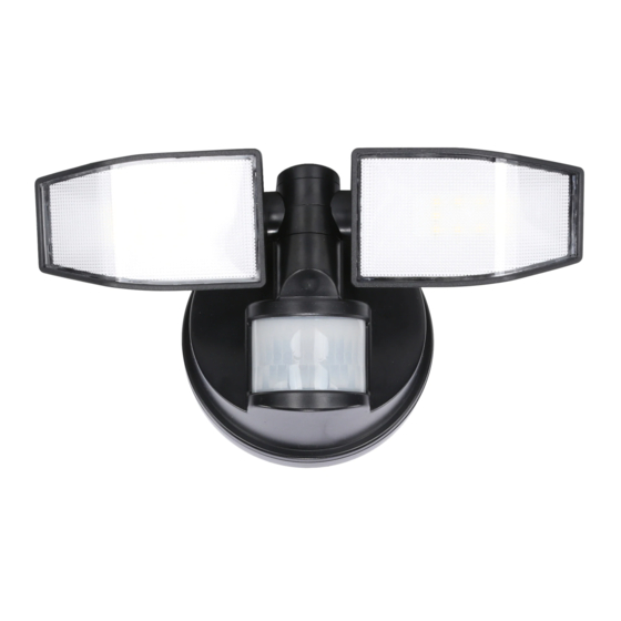
Good Earth Lighting SE1216-BRS-02LF4-G Manual Del Usuario
Ocultar thumbs
Ver también para SE1216-BRS-02LF4-G:
- Manual de instrucciones (4 páginas) ,
- Manual de instrucciones (16 páginas)
Publicidad
Idiomas disponibles
Idiomas disponibles
Light head
Tête de la lampe
Cabeza de luz
Motion Sensor
Détecteur de mouvement
Sensor de movimiento
* Actual hardware may differ from illustration./ * La quincaillerie incluse peut être différente de l'illustration. * Los aditamentos reales pueden diferir de los que se muestran en la ilustración.
IMPORTANT SAFETY INFORMATION
1. LEDs can be damaged by electrostatic discharge (ESD) shock. Before installation, discharge yourself by touching a grounded bare metal surface
to remove this hazard. To avoid damage, do not remove the clear lens over the LED module.
2. NOT FOR EAVE MOUNTING ONTO PERFORATED EAVE MATERIAL: Mounting to anything other than a flat surface can cause water to
seep into the fixture which would then void the IP65 rating.
READ ENTIRE INSTALLATION PROCEDURE BEFORE YOU BEGIN!
Fixture should be mounted 8-10ft high for the fixed PIR to sense motion up to 40 feet away.
1
1
Remove the mounting plate by turning counterclockwise until it comes loose.
Locate the open holes for mounting at the midline of the mounting plate and drill a pilot hole in the center. If mounting onto brick or masonry, drill 3/16 in.
2
hole and place the masonry anchors (AA) in the pilot holes and hammer them into place until flushed with surface of masonry. Place washer (CC) over
the mounting hole and drive long screws (BB) into masonry anchor until snug. DO NOT OVERTIGHTEN. If mounting onto wood surface, drill 1/16 in.
hole and use the wood screws (BB) and washers (CC) provided to secure the mounting plate.
3
OFF ON
3
Remove the screw on the battery compartment cover. Remove the battery compartment cover.
Insert 3 new alkaline C cell batteries (not included) into the battery compartment and orient them with the "+" and "-" markings on the back of the battery
4
compartment. Re-attach the battery compartment cover by aligning the legs on the lower edge of the battery compartment cover onto the fixture body
and close the cover until the catch at the top engages. Re-attach the screw. When ready to use, turn the switch, located below the battery compart-
ment, to "ON". There will be an approximate 15 second delay for the fixture to light up, even if there is motion. This will occur every time the fixture is
turned "OFF" and back "ON" at the switch or the batteries are changed. Do not mix old and new batteries. Cold weather may have a negative impact on
battery life.
5
Attach the security light to the mounting plate by positioning the security light over the mounting plate at an angle. Engage the security light into the
grooves of the mounting base and secure by twisting clockwise until the security light is seated vertically.
Éclairage de sécurité à DEL activé par un mouvement et alimenté par piles
Luz de seguridad LED activada por movimiento y alimentada por baterías
Mounting base
Base de montage
Base de montaje
WARNINGS AND CAUTIONS
INSTALLATION
MASONRY
2
AAx2
AAx2
CCx2
4
CC
LED Motion-Activated Battery Operated Security Light
Model / Model / Modelo #: SE1216-BRS-02LF4-G
Hardware kit* / Trousse de quincaillerie* / Kit de aditamentos*
AAx2
BBx2
Required/ Nécessaire/ Obligatorio
WOOD
3/16 in.
1/16 in.
0,48 cm
0,16 cm
Masonry bit
5
ON
ON
ON
OFF
OFF
OFF
C
Make sure fixture is locked tightly onto the mounting plate to
create a seal to prevent water from entering from the back.
CCx2
3/16 in.
1/16 in.
0,48 cm
0,16 cm
Make sure rubber grommets
are in place behind the screw
heads before screwing in to
insure proper water tight seal.
(Page 1)
(Page 3)
(Page 5)
OPEN
LOCK
UPWARD
1
Publicidad
Tabla de contenido

Resumen de contenidos para Good Earth Lighting SE1216-BRS-02LF4-G
- Página 1 Éclairage de sécurité à DEL activé par un mouvement et alimenté par piles (Page 3) Luz de seguridad LED activada por movimiento y alimentada por baterías (Page 5) Model / Model / Modelo #: SE1216-BRS-02LF4-G Hardware kit* / Trousse de quincaillerie* / Kit de aditamentos* Light head Mounting base...
-
Página 2: Troubleshooting Guide
2) Increase the separation between the equipment and receiver. 3) Connect the equipment into an outlet on a circuit different from that of the receiver. 4) Consult the dealer or an experienced radio/TV technician for help. FCC responsible party name : Good Earth Lighting, Inc. Address: 1400 E Business Center Drive, STE 108, Mount Prospect IL 60056, USA Telephone number: 1-800-291-8838... - Página 3 AVERTISSEMENTS ET MISES EN GARDE INFORMATIONS IMPORTANTES RELATIVES À LA SÉCURITÉ 1. Les DEL peuvent être endommagées par une décharge électrostatique (DES). Avant l’installation, déchargez-vous en touchant une surface en métal mise à la terre pour éliminer un tel risque. Pour éviter tout endommagement, ne retirez pas la lentille transparente qui recouvre le module de DEL.
- Página 4 4) consultez le détaillant ou un technicien en radio ou en télévision expérimenté afin d’obtenir de l’aide. Nom de la partie responsable FCC: Good Earth Lighting, Inc. Adresse: 1400 E Business Center Drive, STE 108, Mount Prospect IL 60056, Numéro de téléphone: 1-800-291-8838 GUIDE DE RECHERCHE DE LA CAUSE DES PROBLÈMES...
-
Página 5: Información De Seguridad Importante
ADVERTENCIAS Y PRECAUCIONES INFORMACIÓN DE SEGURIDAD IMPORTANTE 1. Las luces LED pueden resultar dañadas por una descarga electrostática (DES). Antes de realizar la instalación, descárguese usted tocando una superficie metálica desnuda conectada a tierra para eliminar este peligro. Para evitar daños, no retire el lente transparente ubicado sobre el módulo de luces LED. -
Página 6: Guía De Resolución De Problemas
4) Solicite ayuda al distribuidor o a un técnico con experiencia en radio/TV. Nombre de la parte responsable de la FCC : Good Earth Lighting, Inc. Dirección: 1400 E Business Center Drive, STE 108, Mount Prospect IL 60056, Número de teléfono: 1-800-291-8838 GUÍA DE RESOLUCIÓN DE PROBLEMAS...


