Publicidad
Idiomas disponibles
Idiomas disponibles
Enlaces rápidos
Istruzioni per installazione, uso e manutenzione / Catalogo ricambi
Montage und Bedienungsanleitung / Ersatzteile Katalog
Manuel d'entretien / Catalogue pièces détachées
Installation, use and maintenance instructions / Spare parts list
Installatie-, gebruiks- en onderhoudsvoorschriften / Onderdelencatalogus
Instrucciones de instalación, uso y mantenimiento / Catálogo recambios
I
Rampe gas monostadio
D
Einstufige Gasstrecken
F
Rampe gaz a une allure
st
GB
1
stage gas trains
NL
Gasstraat - eentraps
E
Rampe de gas a 1 llama
CODICE - CODE
3970500 - 3970530 - 3970546 - 3970547
3970531 - 3970544 - 3970548 - 3970553
3970258 - 3970532 - 3970549 - 3970554
CÓDIGO
3970599
3970600
3970550
3970558
MODELLO - MODELL - MODELE
MODEL - MODELO
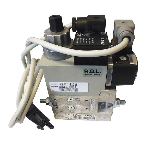
MB 405/1
MB 407/1
MB 410/1
MB 412/1
MB 415/1
20049119 (2) - 03/2017
Publicidad

Manuales relacionados para Riello MB 405/1


Resumen de contenidos para Riello MB 405/1
- Página 1 CODICE - CODE MODELLO - MODELL - MODELE CÓDIGO MODEL - MODELO 3970500 - 3970530 - 3970546 - 3970547 MB 405/1 3970531 - 3970544 - 3970548 - 3970553 MB 407/1 3970599 3970258 - 3970532 - 3970549 - 3970554 MB 410/1...
- Página 3 Informazioni ed avvertenze generali Informazioni ed avvertenze generali Informazioni sul manuale di istruzione 1.1.1 Introduzione In caso di danneggiamento o smarrimento deve essere richiesto un altro esemplare al Servizio Tecnico di Assi- Il manuale di istruzione dato a corredo della rampa gas: stenza di Zona;...
- Página 4 Sicurezza e prevenzione Sicurezza e prevenzione Premessa E’ necessario tenere in considerazione che l’incauto e maldestro rezza tecnica ineccepibili. Eventuali disturbi che possano utilizzo della rampa gas può causare situazioni di pericolo di mor- compromettere la sicurezza devono essere eliminati tempe- te per l’utente o terzi, nonché...
- Página 5 Modelli disponibili Codice Modello Codice Modello 3970600 MB 410/1 - RT 52 3970500 MB 405/1 - RT 20 3970550 MB 412/1 - F3SD 20 3970530 MB 405/1 - RSD 20 3970558 MB 415/1 - F3SD 30 3970546 MB 405/1 - F1SD 20...
- Página 6 Descrizione tecnica Dati tecnici Modello MB 405 - 407 MB 410 - 412 MB 415 Max. pressione di alimentazione 360 mbar (36 kPa) Grado di protezione IP 54 versione “RT ..” - IP 4X versione “SD ..” (*) Temperatura ambiente -15°C fino a + 70 °C Valvola elettromagnetica DIN EN 161, classe A, gruppo 2...
- Página 7 L’ingombro della rampa è riportato in Fig. 2. 20049160 Fig. 2 ØD ØE Codice Modello (Rete) (Bruciatore) 3970500 MB 405/1 - RT 20 – Rp 3/4 Rp 3/4 3970530 MB 405/1 - RSD 20 – Rp 1/2 Rp 1/2* 3970546 MB 405/1 - F1SD 20 –...
- Página 8 Installazione Installazione Note sulla sicurezza per l’installazione Dopo avere effettuato un’accurata pulizia tutt’intorno all’area de- L’installazione della rampa deve essere effettuata stinata all’installazione della rampa ed avere provveduto ad una da personale abilitato, secondo quanto riportato corretta illuminazione dell’ambiente, procedere con le operazioni nel presente manuale ed in conformità...
- Página 9 Installazione Installazione rampa gas Il collegamento tra linea di alimentazione gas e rampa va esegui- to utilizzando la flangia 1), fornita a corredo, fissandola al gruppo Controllare che non vi siano fughe di gas. con i dadi 3). E’ consigliato stringere le viti in modo incrociato. Prestare attenzione nella movimentazione della CAUTELA rampa: pericolo di schiacciamento degli arti.
- Página 10 Le rampe gas riportate in Tab. D sono predisposte in fabbrica per essere collegata secondo lo schema elettrico riportato in Fig. 4. Codice Modello 3970530 MB 405/1 - RSD 20 3970546 MB 405/1 - F1SD 20 3970547 MB 405/1 - F2SD 20...
- Página 11 Messa in funzione, taratura e funzionamento Messa in funzione, taratura e funzionamento Note sulla sicurezza per la prima messa in funzione La prima messa in funzione della rampa deve es- Verificare la corretta funzionalità dei dispositivi di sere effettuata da personale abilitato, secondo regolazione, comando e sicurezza.
- Página 12 Messa in funzione, taratura e funzionamento Perdita di carico La perdita di carico p della rampa viene fornita dal diagramma Rampa gas V ° (Fig. 7); le scale della portata volumetrica valgono rispettiva- 3970546 mente per: aria, 3970547 - 3970500 - 3970530 gas naturale (G20), 3970548 - 3970544 - 3970531 propano (G30),...
- Página 13 Manutenzione Manutenzione Note sulla sicurezza per la manutenzione La manutenzione periodica è essenziale per il buon funziona- mento, la sicurezza, il rendimento e la durata della rampa gas. Togliere l’alimentazione elettrica, agendo sull’in- Essa consente di ridurre i consumi, le emissioni inquinanti e di terruttore generale dell’impianto.
- Página 15 Allgemeine Informationen und Hinweise Allgemeine Informationen und Hinweise Informationen zur Bedienungsanleitung 1.1.1 Einleitung Bei Beschädigung oder Verlust muss ein anderes Exemplar beim gebietszuständigen Technischen Kundendienst ange- Die der Gasarmatur beiliegende Bedienungsanleitung: fordert werden; stellt einen wesentlichen und integrierenden Teil des Pro- ...
- Página 16 Sicherheit und Vorbeugung Sicherheit und Vorbeugung Einleitung Der Einsatz der Gasarmatur muss unter einwandfreien Es muss beachtet werden, dass die unvorsichtige und unge- schickte Verwendung der Gasarmatur zu Situationen führen Sicherheitsbedingungen erfolgen. Eventuelle Störungen, die kann, bei denen Todesgefahr für den Benutzer oder Dritte, sowie die Sicherheit beeinträchtigen können, müssen umgehend die Möglichkeit von Beschädigungen am Brenner oder anderen beseitigt werden.
- Página 17 Erhältliche Modelle Code Modell Code Modell 3970600 MB 410/1 - RT 52 3970500 MB 405/1 - RT 20 3970550 MB 412/1 - F3SD 20 3970530 MB 405/1 - RSD 20 3970558 MB 415/1 - F3SD 30 3970546 MB 405/1 - F1SD 20...
- Página 18 Technische Beschreibung Technische Daten Modell MB 405 - 407 MB 410 - 412 MB 415 Max. Versorgungsdruck 360 mbar (36 kPa) Schutzart IP 54 Ausführung “RT ..” - IP 4X Ausführung “SD ..” (*) Raumtemperatur -15°C bis + 70 °C Elektromagnetventil DIN EN 161, Klasse A, Gruppe 2 Spannung/Frequenz...
- Página 19 Der Platzbedarf der Gasarmatur ist in Abb. 2 angegeben. 20049160 Abb. 2 ØD ØE Code Modell (Netz) (Brenner) 3970500 MB 405/1 - RT 20 – Rp 3/4 Rp 3/4 3970530 MB 405/1 - RSD 20 – Rp 1/2 Rp 1/2* 3970546 MB 405/1 - F1SD 20 –...
- Página 20 Installation Installation Sicherheitshinweise für die Installation Nehmen Sie die Installation nach einer sorgfältigen Reinigung Die Installation der Gasarmatur muss durch Fach- des gesamten zur Installation der Gasarmatur bestimmten Be- personal gemäß den Angaben in diesem Hand- reichs und einer korrekten Beleuchtung des Raums vor. buch sowie in Übereinstimmung mit den gültigen Alle Arbeiten zur Installation, Wartung und De- gesetzlichen Normen und Bestimmungen ausge-...
- Página 21 Installation Installation der Gasarmatur Der Anschluss zwischen der Gaszuleitung und der Armatur er- folgt unter Verwendung des beigepackten Flansches 1), der an Kontrollieren Sie, ob Gas austritt. der Gruppe mit den Muttern 3) befestigt wird. Die Schrauben sollten kreuzweise angezogen werden.
- Página 22 Die in Tab. D angeführten Gasarmaturen wurden werkseitig für den Anschluss laut dem in Abb. 4 angeführten Schaltplan vorge- rüstet. Code Modell 3970530 MB 405/1 - RSD 20 3970546 MB 405/1 - F1SD 20 3970547 MB 405/1 - F2SD 20 3970531...
- Página 23 Inbetriebnahme, Einstellung und Betrieb Inbetriebnahme, Einstellung und Betrieb Sicherheitshinweise für die erstmalige Inbetriebnahme Die erstmalige Inbetriebnahme der Armatur muss Prüfen Sie die richtige Funktionsweise der Ein- durch zugelassenes Fachpersonal gemäß den stell-, Steuer- und Sicherheitsvorrichtungen. Angaben in diesem Handbuch sowie in Überein- stimmung mit den gültigen gesetzlichen Normen ACHTUNG ACHTUNG...
- Página 24 Inbetriebnahme, Einstellung und Betrieb Druckverlust Der Druckverlust p der Gasarmatur ist dem obigen Diagramm Gasarmatur V ° zu entnehmen (Abb. 7); Die Skala der Durchsatzmenge gel- 3970546 ten jeweils für: Luft, 3970547 - 3970500 - 3970530 Erdgas (G20), 3970548 - 3970544 - 3970531 Propan (G30), 3970553 - 3970599 Stadtgas (G140), nur für Anwendungen, die nicht der Gas-...
- Página 25 Wartung Wartung Sicherheitshinweise für die Wartung Die regelmäßige Wartung ist für die gute Funktionsweise, die Si- cherheit, die Leistung und Nutzungsdauer der Gasarmatur we- Schalten Sie die Stromversorgung durch Betäti- sentlich. gen des Hauptschalters der Anlage ab. Sie ermöglicht es, den Verbrauch und die Schadstoffemissionen GEFAHR zu verringern sowie das Produkt im Zeitverlauf zuverlässig zu er- halten.
- Página 27 Informations et avertissements généraux Informations et avertissements généraux Informations sur le manuel d’instructions 1.1.1 Introduction déplacée sur une autre installation. S'il a été endommagé ou égaré demander une autre copie Le manuel d’instructions fourni avec la rampe gaz: au service d'assistance à la clientèle de Zone; ...
- Página 28 Sécurité et prévention Sécurité et prévention Avant-propos L’utilisation de la rampe gaz doit se faire dans des conditions Il est cependant nécessaire de tenir compte du fait qu’une utilisa- tion imprudente ou maladroite de la rampe gaz peut provoquer de sécurité...
- Página 29 Modèles disponibles Code Modèle Code Modèle 3970600 MB 410/1 - RT 52 3970500 MB 405/1 - RT 20 3970550 MB 412/1 - F3SD 20 3970530 MB 405/1 - RSD 20 3970558 MB 415/1 - F3SD 30 3970546 MB 405/1 - F1SD 20...
- Página 30 Description technique Données techniques Modèle MB 405 - 407 MB 410 - 412 MB 415 Pression max. d’alimentation 360 mbar (36 kPa) Degré de protection IP 54 version « RT ..» - IP 4X version «SD ..» (*) Température ambiante -15°C jusqu’à...
- Página 31 L’encombrement de la rampe gaz est indiqué dans la Fig. 2. 20049160 Fig. 2 ØD ØE Code Modèle (Réseau) (Brûleur) 3970500 MB 405/1 - RT 20 – Rp 3/4 Rp 3/4 3970530 MB 405/1 - RSD 20 – Rp 1/2 Rp 1/2* 3970546 MB 405/1 - F1SD 20 –...
- Página 32 Installation Installation Indications concernant la sécurité pour l’installation Après avoir nettoyé soigneusement tout autour de la zone où la L’installation la rampe doit être effectuée par du rampe doit être installée et à avoir bien éclairé le milieu, effectuer personnel habilité, selon les indications reportées les opérations d’installation.
- Página 33 Installation Installation de la rampe gaz Le branchement entre ligne d’alimentation du gaz et rampe doit être effectué en utilisant la bride 1) fournie, en la fixant au groupe Contrôler l’absence de fuites de gaz. avec les écrous 3). Il est conseillé de serrer les vis par un serrage en croix.
- Página 34 Les rampes gaz indiquées dans le Tab. D sont prévues en usine pour être branchées selon le schéma électrique indiqué sur la Fig. 4. Code Modèle 3970530 MB 405/1 - RSD 20 3970546 MB 405/1 - F1SD 20 3970547 MB 405/1 - F2SD 20 3970531...
- Página 35 Mise en service, réglage et fonctionnement Mise en service, réglage et fonctionnement Indications concernant la sécurité pour la première mise en marche La première mise en marche de la rampe doit être Vérifier le bon fonctionnement des dispositifs de effectuée par un personnel habilité, selon les indi- réglage, de commande et de sécurité.
- Página 36 Mise en service, réglage et fonctionnement Perte de charge La perte de charge p de la rampe est fournie par le diagramme Rampe gaz V ° (Fig. 7);les échelles du débit volumétrique ont respective- 3970546 ment une valeur de: air, 3970547 - 3970500 - 3970530 gaz naturel (G20), 3970548 - 3970544 - 3970531...
- Página 37 Entretien Entretien Indications concernant la sécurité pour l’entretien L’entretien périodique est indispensable pour un bon fonctionne- ment, la sécurité, le rendement et la durée de vie de la rampe Couper l’alimentation électrique en appuyant sur gaz. l’interrupteur général de l’installation. Il permet de réduire la consommation, les émissions polluantes DANGER et au produit de rester fiable dans le temps.
- Página 39 Information and general warnings Information and general warnings Information about the instruction manual 1.1.1 Introduction If the manual is lost or damaged, another copy must be requested from the Technical Assistance Service of the The instruction manual supplied with the gas train: area;...
- Página 40 Safety and prevention Safety and prevention Introduction The gas train must be used in impeccably secure conditions. It is necessary, however, to bear in mind that the imprudent and clumsy use of the gas train may lead to situations of death risk for Any disturbances that could compromise safety must be the user or third parties, as well as the damaging of the burner or quickly eliminated.
- Página 41 Models available Code Model Code Model 3970600 MB 410/1 - RT 52 3970500 MB 405/1 - RT 20 3970550 MB 412/1 - F3SD 20 3970530 MB 405/1 - RSD 20 3970558 MB 415/1 - F3SD 30 3970546 MB 405/1 - F1SD 20...
- Página 42 Technical description Technical data Model MB 405 - 407 MB 410 - 412 MB 415 Max. power supply pressure 360 mbar (36 kPa) Protection level IP 54 “RT ..” version - IP 4X “SD ..” version (*) Ambient temperature -15°C up to + 70 °C Electromagnetic valve DIN EN 161, class A, group 2 Voltage/frequency...
- Página 43 The maximum dimensions of the train are given in Fig. 2. 20049160 Fig. 2 ØD ØE Code Model (Network) (Burner) 3970500 MB 405/1 - RT 20 – Rp 3/4 Rp 3/4 3970530 MB 405/1 - RSD 20 – Rp 1/2 Rp 1/2* 3970546 MB 405/1 - F1SD 20 –...
- Página 44 Installation Installation Notes on safety for the installation After carefully cleaning all around the area where the train will be Train installation must be carried out by qualified installed, and arranging the correct lighting of the environment, personnel, as indicated in this manual and in com- proceed with the installation operations.
- Página 45 Installation Gas train installation The connection between the gas feeding line and the train is cre- ated using the flange 1), supplied with the system, by fastening it Check that there are no gas leaks. to the unit with nuts 3). It is best to tighten screws in a criss-cross pattern.
- Página 46 The gas trains shown in Tab. D are prepared in the factory to be connected in accordance with the electrical diagram shown in Fig. 4. Code Model 3970530 MB 405/1 - RSD 20 3970546 MB 405/1 - F1SD 20 3970547 MB 405/1 - F2SD 20 3970531...
- Página 47 Activation, calibration and functioning Activation, calibration and functioning Notes on safety for the first start-up The first start-up of the burner must be carried out Check the correct working of the adjustment, com- by qualified personnel, as indicated in this manual mand and safety devices.
- Página 48 Activation, calibration and functioning Pressure loss The gas train pressure loss p is provided from the diagram (Fig. Gas train V ° 7); the scales of the volumetric output are valid respectively 3970546 for: air, 3970547 - 3970500 - 3970530 natural gas (G20), 3970548 - 3970544 - 3970531 propane (G30),...
- Página 49 Maintenance Maintenance Notes on safety for the maintenance The periodic maintenance is essential for the good operation, safety, yield and duration of the gas train. Disconnect the electrical power using the main It allows you to reduce consumption and polluting emissions and switch.
- Página 51 Algemene informatie en waarschuwingen Algemene informatie en waarschuwingen Informatie over de handleiding 1.1.1 Inleiding In geval van beschadiging of verlies moet u een ander exemplaar aanvragen bij de Technische Hulpdienst in uw De handleiding die samen met de gasstraat geleverd wordt: buurt;...
- Página 52 Veiligheid en preventie Veiligheid en preventie Inleiding De gasstraat moet gebruikt worden in onberispelijke tech- Onvoorzichtig en onhandig gebruik van de gasstraat kan gevaar- lijke situaties, en zelfs de dood, veroorzaken voor de gebruiker of nisch veilige omstandigheden. Eventuele storingen die de voor derden, evenals beschadigingen van de brander of andere veiligheid negatief kunnen beïnvloeden moeten tijdig geëli- goederen.
- Página 53 Beschikbare modellen Code Model Code Model 3970600 MB 410/1 - RT 52 3970500 MB 405/1 - RT 20 3970550 MB 412/1 - F3SD 20 3970530 MB 405/1 - RSD 20 3970558 MB 415/1 - F3SD 30 3970546 MB 405/1 - F1SD 20...
- Página 54 Technische beschrijving Technische gegevens Model MB 405 - 407 MB 410 - 412 MB 415 Max. inlaatdruk 360 mbar (36 kPa) Beschermingsgraad IP 54 versie “RT ..” - IP 4X versie “SD ..” (*) Omgevingstemperatuur -15°C tot + 70°C Elektromagnetisch ventiel DIN EN 161, klasse A, groep 2 Spanning/frequentie ~ (AC) 50-60 Hz, 230 V - 15 % + 10 %...
- Página 55 De afmetingen van de gasstraat worden aangeduid in Fig. 2. 20049160 Fig. 2 ØD ØE Code Model (Net) (Brander) 3970500 MB 405/1 - RT 20 – Rp 3/4 Rp 3/4 3970530 MB 405/1 - RSD 20 – Rp 1/2 Rp 1/2* 3970546 MB 405/1 - F1SD 20 –...
- Página 56 Installatie Installatie Aantekeningen over de veiligheid bij de installatie Nadat het gebied rondom de zone van de installatie van de gas- De installatie van de gasstraat moet uitgevoerd straat zorgvuldig is gereinigd en een gepaste verlichting van de worden door bevoegd personeel, volgens de omgeving is voorzien, kunnen de handelingen van de installatie aanduidingen in deze handleiding en in overeen- begonnen worden.
- Página 57 Installatie Installatie gasstraat De aansluiting tussen de gastoevoerlijn en de straat moet uitge- voerd worden met behulp van de bijgeleverde flens 1) door deze Controleer of geen gaslekken aanwezig zijn. op de groep te bevestigen met behulp van de moeren 3). Er wordt aangeraden de schroeven kruiselings aan te draaien.
- Página 58 De gasstraten die worden aangeduid in Tab. D zijn in de fabriek voorzien voor de aansluiting volgens het elektrische schema dat wordt aangeduid in Fig. 4. Code Model 3970530 MB 405/1 - RSD 20 3970546 MB 405/1 - F1SD 20 3970547 MB 405/1 - F2SD 20 3970531...
- Página 59 Inbedrijfstelling, ijking en werking Inbedrijfstelling, ijking en werking Aantekeningen over de veiligheid bij de eerste inbedrijfstelling De eerste inbedrijfstelling van de gasstraat moet Controleer of de mechanismen voor regeling, be- uitgevoerd worden door bevoegd personeel, vol- diening en veiligheid correct functioneren. gens de aanduidingen in deze handleiding en in overeenstemming met de geldende normen en OPGELET...
- Página 60 Inbedrijfstelling, ijking en werking Drukverlies De grafiek geeft de drukverliezen p van de gasstraat aan Gasstraat V ° (Fig. 7) de schalen van het volumedebiet gelden voor: 3970546 lucht, aardgas (G20), 3970547 - 3970500 - 3970530 propaan (G30), 3970548 - 3970544 - 3970531 stadsgas (G140), enkel voor toepassingen die niet onderhe- 3970553 - 3970599 vig zijn aan Richtlijn Gastoestellen (2009/142/EG).
- Página 61 Onderhoud Onderhoud Opmerkingen over de veiligheid voor het onderhoud Het periodieke onderhoud is van essentieel belang voor de cor- recte functionering, de veiligheid, het rendement en de duur- Onderbreek de stroomtoevoer met de hoofdscha- zaamheid van de gasstraat. kelaar van de inrichting. Dankzij het onderhoud worden het verbruik en de vervuilende uit- GEVAAR stoten gereduceerd en blijft het product betrouwbaar door de tijd...
- Página 63 Informaciones y advertencias generales Informaciones y advertencias generales Información sobre el manual de instrucciones 1.1.1 Introducción otra instalación. En caso de daño o extravío debe solicitarse otro ejemplar al El manual de instrucción entregado junto con la rampa de gas: Servicio Técnico de Asistencia de la Zona;...
- Página 64 Seguridad y prevención Seguridad y prevención Introducción Es necesario considerar que usar la rampa gas de modo impru- de seguridad técnica irreprochables. Los eventuales incon- dente y sin experiencia puede causar situaciones de peligro mor- venientes que puedan comprometer la seguridad se deben tales para el usuario o terceros, además de daños al quemador eliminar inmediatamente.
- Página 65 Modelos disponibles Código Modelo Código Modelo 3970600 MB 410/1 - RT 52 3970500 MB 405/1 - RT 20 3970550 MB 412/1 - F3SD 20 3970530 MB 405/1 - RSD 20 3970558 MB 415/1 - F3SD 30 3970546 MB 405/1 - F1SD 20...
- Página 66 Descripción técnica Datos técnicos Modelo MB 405 - 407 MB 410 - 412 MB 415 Presión máxima de alimentación 360 mbar (36 kPa) Grado de protección IP 54 versión “RT ..” - IP 4X versión “SD ..” (*) Temperatura ambiente -15°C hasta + 70 °C Válvula electromagnética DIN EN 161, clase A, grupo 2...
- Página 67 Las dimensiones de la rampa de gas se indican en la Fig. 2. 20049160 Fig. 2 ØD ØE Código Modelo (Red) (Quemador) 3970500 MB 405/1 - RT 20 – Rp 3/4 Rp 3/4 3970530 MB 405/1 - RSD 20 – Rp 1/2 Rp 1/2* 3970546 MB 405/1 - F1SD 20 –...
- Página 68 Instalación Instalación Notas sobre la seguridad para la instalación Después de realizar una cuidadosa limpieza en toda el área de La instalación de la rampa debe ser realizada por la instalación de la rampa de gas y de proveer una correcta ilu- personal habilitado según todo lo indicado en el minación del ambiente, proceder con las operaciones de instala- presente manual y en conformidad con las nor-...
- Página 69 Instalación Instalación rampa de gas La conexión entre la línea de alimentación gas y la rampa se debe realizar utilizando la brida 1), suministrada, fijándola al gru- Controlar la ausencia de perdidas de gas. po con las tuercas 3). Se aconseja apretar los tornillos de modo cruza- Trasladar la rampa de gas con mucho cuidado: PRECAUCIÓN peligro de aplastamiento de las extremidades.
- Página 70 Las rampas de gas indicadas en la Tab. D están preparadas de fábrica para ser conectadas según el esquema eléctrico indicado en Fig. 4. Código Modelo 3970530 MB 405/1 - RSD 20 3970546 MB 405/1 - F1SD 20 3970547 MB 405/1 - F2SD 20 3970531...
- Página 71 Puesta en funcionamiento, calibración y funcionamiento Puesta en funcionamiento, calibración y funcionamiento Notas sobre la seguridad para la primera puesta en funcionamiento La primera puesta en funcionamiento de la rampa Comprobar el correcto funcionamiento de los dis- debe ser realizada por personal habilitado según positivos de regulación, mando y seguridad.
- Página 72 Puesta en funcionamiento, calibración y funcionamiento Pérdida de carga La pérdida de carga p de la rampa se indica en el diagrama Rampa de gas V ° (Fig. 7); las escalas del caudal volumétrico valen respectiva- 3970546 mente para: aire 3970547 - 3970500 - 3970530 gas natural (G20), 3970548 - 3970544 - 3970531...
- Página 73 Mantenimiento Mantenimiento Notas sobre la seguridad para el mantenimiento El mantenimiento periódico es fundamental para el buen funcio- namiento, la seguridad, el rendimiento y la duración de la rampa Cortar la alimentación eléctrica mediante el inte- de gas. rruptor general de la instalación. El mismo permite reducir los consumos, las emisiones contami- PELIGRO nantes y mantener el producto fiable a través del tiempo.
- Página 74 MB 405/1 MB 407/1 MB 405/1 MB 407/1 3970530 - 3970546 - 3970547 3970531 - 3970544 - 3970548 3970500 3970553 - 3970599 MB 410/1 MB 412/1 MB 410/1 3970532 - 3970549 3970550 3970258 - 3970554 - 3970600 MB 415/1 3970558...
- Página 75 COD. DESCRIZIONE DESCRIPTION DESCRIPTION BESCHREIBUNG DENOMINACION • • • • • • • • • • • • • • • • 3012196 PRESSOSTATO GAS GAS PRESSURE SWITCH PRESSOSTAT GAZ GASDRUCKWÄCHTER PRESOSTATO DE GAS • • • • • • • • • 3008532 BOBINA COIL...
- Página 76 Con riserva di modifiche - Änderungen vorbehalten - Sous réserve de modifications - Subject to modifications - Onder voorbehoud van wijzigingen Con la posibilidad de modificaciónes...