Publicidad
Enlaces rápidos
Publicidad

Manuales relacionados para Sauder 426440


Resumen de contenidos para Sauder 426440
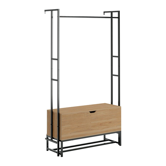
- Página 1 You'll love what we have in storage.
- Página 2 Table of Contents Assembly Tools Required Part Identifi cation No. 2 Phillips Screwdriver Tip Shown Actual Size Hardware Identifi cation Assembly Steps 6-21 Electric drill with 5/16" bit (ONLY in indicated step) Français 22-24 Español 25-27 Safety 28-30 Warranty Page 2...
- Página 3 Now you know Part Identifi cation our ABCs. å While not all parts are labeled, some of the parts will have a label or an inked letter on the edge to help distinguish similar parts from each other. Use this part identifi cation to help identify similar parts. FRONT (1) TOP (1) LOWER FRAME (2)
- Página 4 Hardware Identifi cation å Screws are shown actual size. You may receive extra hardware with your unit. HIDDEN CAM - 4 CAM SCREW - 4 WOOD DOWEL -12 REAR HINGE - 3 APPLIQUE CARD - 1 RIGHT HINGE - 1 BUMPER CARD - 1 LEFT HINGE - 1 WALL ANCHOR - 2...
- Página 5 Hardware Identifi cation å Screws are shown actual size. You may receive extra hardware with your unit. 1-3/16" HEX HEAD SCREW - 18 2" PAN HEAD SCREW - 2 1-9/16" PAN HEAD SCREW - 12 1/2" HEX HEAD SCREW - 8 1-3/8"...
- Página 6 Hardware Usage Guide HOW TO USE A HIDDEN CAM & CAM SCREW OR CAM DOWEL NOTE: Various CAM SCREWS or a CAM DOWEL may be used. Turn the CAM SCREW or gently tap the CAM DOWEL until the shoulder is against the surface of the part.
- Página 7 Step 1 Assemble your unit on a carpeted fl oor or on the empty å carton to avoid scratching your unit or the fl oor. Just think. The sooner you do this, the sooner Turn four CAM SCREWS (2) into the FRONT (A). å...
- Página 8 Step Step 2 Insert two WOOD DOWELS (3) into the FRONT (A). å Fasten the ENDS (B and C) to FRONT (A). Tighten four å HIDDEN CAMS. NOTE: Be sure the WOOD DOWELS in the FRONT insert å into the ENDS. Notch Finished edge Page 8...
- Página 9 Step Step 3 Insert two WOOD DOWELS (3) into the ENDS (B and C). å Fasten the BACK (D) to the ENDS (B and C). Use four å 1-9/16" PAN HEAD SCREWS (15). NOTE: Be sure the WOOD DOWELS in the ENDS insert å...
- Página 10 Step Step 4 Carefully turn your unit on its top edges. å These holes are further from this edge Insert eight WOOD DOWELS (3) into the SHELF (E). å Fasten the BOTTOM (E) to the FRONT (A), ENDS (B and C), å...
- Página 11 Step Step 5 Carefully turn your unit onto the BACK (D). å Fasten the REAR HINGES (4) to the BACK (D). Use nine å BLACK 9/16" PAN HEAD SCREWS (16). 9/16" PAN HEAD SCREW (9 used in this step) Page 11...
- Página 12 Step Step 6 Fasten the TOP (F) to the BACK (D). Use six 9/16" PAN å HEAD SCREWS (16). 9/16" PAN HEAD SCREW (6 used in this step) Page 12...
- Página 13 Step Step 7 IMPORTANT: You will need someone's help in this step. å Fasten the LEFT HINGE (5) to the LEFT END (B) and the å RIGHT HINGE (6) to the RIGHT END (C). Use four 9/16" PAN HEAD SCREWS (16). Fasten the LEFT HINGE (5) and RIGHT HINGE (6) to å...
- Página 14 Step Step 8 Fasten the LEGS (G and H) to the BRACES (J) å and RACK (K). Tighten eight 1-3/16" HEX HEAD SCREWS (12) using the L-WRENCH (11). NOTE: You should start each SCREW a few turns before å completely tightening any of them. Surface with fewer holes Surface with more holes 1-3/16"...
- Página 15 Step Step 9 Fasten the BRACES (J) to the BOTTOM (E). Tighten four å 1-3/16" HEX HEAD SCREWS (12) using the L-WRENCH (11). Now might be a good time to refresh NOTE: You should start each SCREW a few turns before å...
- Página 16 Step Step 10 Fasten a LOWER FRAME (L) and WASHERS (10) to the å LEFT END (B) and LEFT LEG (G). Tighten two 1-3/16" HEX HEAD SCREWS (12) and two 1-3/8" HEX HEAD SCREW (17) as shown using the L-WRENCH (11). NOTE: You should start each SCREW a few turns before å...
- Página 17 Step Step 11 Fasten the remaining LOWER FRAME (L) and WASHERS (10) to å the RIGHT END (C) and RIGHT LEG (H). Tighten two 1-3/16" HEX HEAD SCREWS (12) and two 1-3/8" HEX HEAD SCREW (17) as shown using the L-WRENCH (11). NOTE: You should start each SCREW a few turns before completely å...
- Página 18 Step Step 12 Fasten the ROD (N) to the UPPER FRAMES (M). å Tighten two 1-3/16" HEX HEAD SCREWS (12) using the L-WRENCH (11). NOTE: You should start each SCREW a few turns before å completely tightening any of them. 1-3/16"...
- Página 19 Step Step 13 Fasten the UPPER FRAMES (M) to the LOWER FRAMES (L). Tighten å eight 1/2" HEX HEAD SCREWS (14) using the L-WRENCH (11). If you're doing this to help a friend, don't NOTE: You should start each SCREW a few turns before completely å...
- Página 20 Step Step 14 -Carefully stand your unit upright against the wall in its fi nal location. Strike a mark through the center of the hole in å the UPPER FRAMES (M). Lay your unit down. -Drill a 5/16" hole on the marks. å...
- Página 21 Step Step 15 Peel APPLIQUES from the APPLIQUE CARD (8) and stick them onto each visible HIDDEN CAM. å Peel the BUMPERS from the BUMPER CARD (7) and stick them onto the top edges of the ENDS (B, and C) where å...
- Página 22 Utilisez les instructions d’ a ssemblage en français avec les schémas étape par étape du manuel d’instruction en anglais. Chaque étape en français correspond à la même étape en anglais. Comparer la “Liste de pièces” ci-dessous avec la “PART IDENTIFICATION” du manuel en anglais pour vous familiariser avec les pièces avant l’...
- Página 23 Guide d'utilisation de la visserie ÉTAPE 4 UTILISATION DE LA EXCENTRIQUE ESCAMOTABLE ET DE LA Placer, avec précaution, l’unité sur ses bords supérieurs. VIS D'EXCENTRIQUE OU DE LA CHEVILLE D’EXCENTRIQUE Insérer huit CHEVILLES EN BOIS (3) dans la TABLETTE (E). REMARQUE : Plusieurs VIS D'EXCENTRIQUE ou une CHEVILLE Fixer le DESSOUS (E) au DEVANT (A), aux EXTRÉMITÉS (B et C) D’EXCENTRIQUE peut être utilisé.
- Página 24 ÉTAPE 8 ÉTAPE 12 Fixer les PIEDS (G et H) aux ENTRETOISES (J) et au RACK (K). Fixer la TRINGLE (N) aux CADRES SUPÉRIEURS (M). Serrer deux Serrer huit VIS TÊTE HEX 30 mm (12) avec la CLÉ EN L (11). VIS TÊTE HEX 30 mm (12) à...
- Página 25 Use estas instrucciones de ensamblaje en español junto con las fi guras paso-a-paso provistas en el folleto inglés. Cada paso en español corresponde al mismo paso en inglés. Compare la “Lista de Part” abajo con la “Part Identifi cation” en el folleto en inglés para familiarizarse con Las partes de ensamblaje.
- Página 26 Guía de uso de herrajes PASO 4 CÓMO UTILIZAR EL EXCÉNTRICO ESCONDIDO Y LA BIELA DE Cuidadosamente voltee la unidad para que repose sobre los EXCÉNTRICO O PASADOR DE EXCÉNTRICO bordes superiores. NOTA: Varias BIELAS DE EXCÉNTRICO o un PASADOR DE Inserte ocho PASADORES DE MADERA (3) en el ESTANTE (E).
- Página 27 PASO 8 PASO 12 Fije las PATAS (G y H) a las RIOSTRAS (J) y al ANAQUEL (K). Apriete Fije la VARILLA (N) a los MARCOS SUPERIORES (M). Apriete dos los ocho TORNILLOS DE CABEZA HEXAGONAL de 30 mm (12) TORNILLOS DE CABEZA HEXAGONAL de 30 mm (12) utilizando utilizando la LLAVE EN L (11).
- Página 28 WARNING Please use your furniture correctly and safely. Improper use can cause safety hazards, or damage to your furniture or household items. Carefully read the following safety information. Death or serious injury may occur when children climb on furniture. A remote control, toys or other items placed on the furniture may encourage a child to climb on the furniture which could cause it to tip-over and result in serious injury or death.
- Página 29 AVERTISSEMENT Prière d'utiliser le mobilier à bon escient et avec prudence. Une mauvaise utilisation peut être à l'origine de risques d'accident ou peut endommager le mobilier et les articles ménagers. Lire attentivement l'information suivante sur la sécurité. La mort voire de graves blessures peuvent se produire lorsque des enfants grimpent sur les meubles. Une télécommande, des jouets ou d’...
- Página 30 ADVERTENCIA Por favor use el mobiliario correcta y seguramente. El mal uso puede causar riesgos de seguridad o daño a las unidades o artículos domésticos. Lea cuidadosamente la siguiente información de seguridad. Pueden suceder lesiones graves o la muerte cuando los niños se suben en los muebles. Un control remoto, juguetes u otros artículos colocados en los muebles pueden alentar a un niño a subirse en el mueble, lo cual podría causar que se derribe y resultaría en lesiones graves o la muerte.
- Página 31 5-YEAR LIMITED WARRANTY 1. We provides limited warranty coverage to the original purchaser of this product for a period of fi ve years from the date of purchase against defects in materials or workmanship of furniture components. As used in this Warranty, “defect” means imperfections in components which substantially impair the utility of the product.