Publicidad
CONTACT US FIRST
CONTACT US FIRST
sauder.com
sauder.com
sauder.com
BEFORE MAKING ANY RETURNS TO THE STORE.
BEFORE MAKING ANY RETURNS TO THE RETAILER.
sauder.com/service
Visit
Prefer the phone? Give us a ring at
Customer Service is available Monday-Friday - 9 a.m. to 5:30 p.m. EST (except holidays)
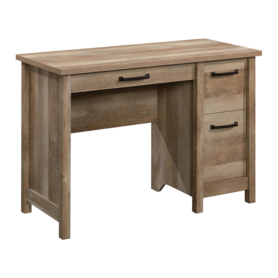
Desk
Cannery Bridge Collection | Model 426140
Sauder.com
Share your journey!
to order replacement parts, view video assembly tips, or chat with a live rep.
1-800-523-3987
.
Sit and surf.
NOTE: THIS INSTRUCTION
BOOKLET CONTAINS IMPORTANT
SAFETY INFORMATION.
PLEASE READ AND KEEP FOR
FUTURE REFERENCE.
English pg 1-39
Français pg 40-43
Español pg 44-48
Lot # 540279
02/27/20
Purchased: __________________
Publicidad
Tabla de contenido

Manuales relacionados para Sauder Cannery Bridge 426140


Resumen de contenidos para Sauder Cannery Bridge 426140
- Página 1 CONTACT US FIRST CONTACT US FIRST sauder.com sauder.com sauder.com BEFORE MAKING ANY RETURNS TO THE STORE. BEFORE MAKING ANY RETURNS TO THE RETAILER. sauder.com/service Visit to order replacement parts, view video assembly tips, or chat with a live rep. 1-800-523-3987 Prefer the phone? Give us a ring at Customer Service is available Monday-Friday - 9 a.m.
- Página 2 Table of Contents Assembly Tools Required Part Identification No. 2 Phillips Screwdriver Tip Shown Actual Size Hardware Identification Assembly Steps 6-39 Hammer Français 40-43 Not actual size Español 44-48 Safety 49-50 Warranty Page 2 426140 www.sauder.com/service...
-
Página 3: Part Identification
LARGE RIGHT DRAWER SIDE (1) BOTTOM (1) LARGE DRAWER FRONT (1) LARGE LEFT DRAWER SIDE (1) END MOLDING (2) BOTTOM MOLDING (1) D150 DRAWER BACK (1) EXTENSION BLOCK (1) D150 D953 D151 D544 D545 D954 D543 D542 www.sauder.com/service 426140 Page 3... - Página 4 35MC 10A SLIDE CAM - 4 FILE ROD - 2 FILE GLIDE - 2 HIDDEN CAM - 19 CAM DOWEL - 10 10F TWIST-LOCK CAM SCREW - 9 FASTENER - 4 WOOD DOWEL - 3 ® Page 4 426140 www.sauder.com/service...
- Página 5 30S BLACK 1-9/16" FLAT HEAD SCREW - 14 BLACK 1-1/8" MACHINE SCREW - 2 100S BLACK 2-3/4" FLAT HEAD SCREW - 6 BLACK 9/16" FLAT HEAD SCREW - 4 113S BLACK 1-15/16" FLAT HEAD SCREW - 2 www.sauder.com/service 426140 Page 5...
- Página 6 Step 1 Look for this icon. It means a video assembly tip is available at www.sauder.com/service/tips Find the numbered video or scan the QR code. å Assemble your unit on a carpeted floor or on the empty carton to avoid scratching your unit or the floor.
- Página 7 Push a HIDDEN CAM into Insert the CAM SCREW into the HIDDEN CAM. the part. The arrow in the Tighten the HIDDEN CAM. HIDDEN CAM must point toward the hole in the edge of the board. Hole www.sauder.com/service 426140 Page 7...
- Página 8 Turn three CAM SCREWS (8F) into one of the FRONT LEGS (L). you do this, the sooner you do something else. å Insert one WOOD DOWEL (15F) into one of the FRONT LEGS (L). Arrow Arrow Page 8 426140 www.sauder.com/service...
- Página 9 BLACK 2-3/4" FLAT HEAD SCREW (3 used in this step) S u r f a c i t h H I D D E N These surfaces The LEGS will should be even. overhang this edge. www.sauder.com/service 426140 Page 9...
- Página 10 å Fasten a CABINET LEFT (35GB) to the LEFT END (B). Use two GOLD 5/16" FLAT HEAD SCREWS (3S) through holes #1 and #3. GOLD 5/16" FLAT HEAD SCREW (2 used for the RAILS) Roller end Page 10 426140 www.sauder.com/service...
- Página 11 2. Tighten the FASTENER with a Phillips screwdriver as tight as possible. Dowel end Step 5 å To begin assembly, push four SAUDER TWIST-LOCK® FASTENERS (10F) into the large holes in the MODESTY PANEL (D). Do not tighten the TWIST-LOCK® FASTENERS in this step. www.sauder.com/service 426140...
- Página 12 Do not stand the unit upright without the BACK fastened. The unit may collapse. i t h ® f a c S u r - L O I S T E R S T E N F A S Page 12 426140 www.sauder.com/service...
- Página 13 D E N i t h E R S T E N F A S K ® T - L W I S u t T i t h o f a c S u r www.sauder.com/service 426140 Page 13...
- Página 14 å Push five HIDDEN CAMS (1F) into the UPRIGHT (C). å Turn three CAM SCREWS (8F) into one of the FRONT LEGS (L). å Insert a WOOD DOWEL (15F) into the FRONT LEG (L). Arrow Arrow Page 14 426140 www.sauder.com/service...
- Página 15 NOTE: Be sure the WOOD DOWEL in the FRONT LEG insert into the UPRIGHT. S u r f a c i t h H I D D E N The LEGS will These surfaces overhang this edge. should be even. www.sauder.com/service 426140 Page 15...
- Página 16 Step 10 å Fasten the CABINET LEFT (40CB) to the UPRIGHT (C). Use two GOLD 5/16" FLAT HEAD SCREWS (3S) through holes #1 and #3. GOLD 5/16" FLAT HEAD SCREW (2 used for the RAILS) Roller end Page 16 426140 www.sauder.com/service...
- Página 17 NOTE: The EXTENSION SLIDES will be used later for the DRAWERS. 40MC 40MA Push the black lever in and pull the SLIDE from the RAIL. GOLD 5/16" FLAT HEAD SCREW (4 used for the RAILS) Open end www.sauder.com/service 426140 Page 17...
- Página 18 Fasten a CABINET RIGHT (35GA) to the UPRIGHT (C). Use two GOLD 5/16" FLAT HEAD SCREWS (3S) through holes #1 and #3. GOLD 5/16" FLAT HEAD SCREW (2 used for the RAILS) Roller end BLACK 1-1/8" PAN HEAD SCREW (2 used in this step) Page 18 426140 www.sauder.com/service...
- Página 19 Fasten the UPRIGHT (C) to the MODESTY PANEL (D). Use two BLACK 1-15/16" FLAT HEAD SCREWS (113S). 113S BLACK 1-15/16" FLAT HEAD SCREW (2 used in this step) S u r f a c i t h H I D D E N Roller end www.sauder.com/service 426140 Page 19...
- Página 20 Push four HIDDEN CAMS (1F) into the BOTTOM (E). Then, insert the metal end of a CAM DOWEL (2F) into each HIDDEN CAM. Do not tighten the HIDDEN CAMS in this step. Arrow Metal end Arrow Metal end Page 20 426140 www.sauder.com/service...
- Página 21 å *U.S. Patent No. 5,499,886 Notched edge å Fasten the BOTTOM (E) to the UPRIGHT (C). Tighten two HIDDEN CAMS. These surfaces should be even. The groove is closer to this edge. www.sauder.com/service 426140 Page 21...
- Página 22 NOTE: If the MOLDING comes up off of the SCREWS, remove it and slide it on again. Apply pressure with your hands as you guide the MOLDINGS over the SCREWS and onto the ENDS. Shoulder BLACK 9/16" FLAT HEAD SCREW (2 used in this step) Page 22 426140 www.sauder.com/service...
- Página 23 å Push five HIDDEN CAMS (1F) into the RIGHT END (A). å Turn three CAM SCREWS (8F) into the remaining FRONT LEG (L). å Insert a WOOD DOWEL (15F) into the FRONT LEG (L). Arrow Arrow www.sauder.com/service 426140 Page 23...
- Página 24 BLACK 2-3/4" FLAT HEAD SCREW (3 used in this step) These surfaces should be even. D E N H I D i t h f a c S u r The LEGS will overhang this edge. Page 24 426140 www.sauder.com/service...
- Página 25 Use two GOLD 5/16" FLAT HEAD SCREWS (3S) through holes #1 and #3. Do not tighten the HIDDEN CAMS in this step. Metal end Roller end GOLD 5/16" FLAT HEAD SCREW (2 used for the RAILS) www.sauder.com/service 426140 Page 25...
- Página 26 EXTENSION RAIL in to find the other hole that lines up with the hole in the RIGHT END. Turn a SCREW into this hole. Open end GOLD 5/16" FLAT HEAD SCREW (2 used for the RAILS) Page 26 426140 www.sauder.com/service...
- Página 27 Step 21 å Fasten the RIGHT END (A) to the BOTTOM (E) and TOP (J). Tighten four HIDDEN CAMS. www.sauder.com/service 426140 Page 27...
- Página 28 NOTE: Be sure to tap NAILS into the holes that line up over the BOTTOM (E). å NOTE: Perforations have been provided for access through the BACK. Carefully cut out the holes needed. NAIL These holes must line up (16 used in this step) over the BOTTOM (E). Page 28 426140 www.sauder.com/service...
- Página 29 Fasten the PENCIL DRAWER BACK (D545) to the DRAWER BOX FRONT (D542) and PENCIL PENCIL DRAWER SIDES (D543 and D544). Use two DRAWER BACK (D545). Use two BLACK 1-9/16" BLACK 1-9/16" FLAT HEAD SCREWS (30S). FLAT HEAD SCREWS (30S). www.sauder.com/service 426140 Page 29...
- Página 30 Roller end BLACK 7/8" LARGE HEAD SCREW (2 used in this step) D543 Roller end D542 D544 Drawer Slide GOLD 5/16" FLAT HEAD SCREW (4 used for the SLIDES) Center the screw in the oval hole. Page 30 426140 www.sauder.com/service...
- Página 31 Step Step 25 å Fasten a PULL (101K) to the PENCIL DRAWER FRONT (H). Use two BLACK 1-1/8" MACHINE SCREWS (21S). BLACK 1-1/8" MACHINE SCREW (2 used in this step) 101K www.sauder.com/service 426140 Page 31...
- Página 32 Fasten the LARGE DRAWER BACK (D151) to the LARGE DRAWER SIDES (D28 and D29). Use four BLACK 1-9/16" FLAT HEAD SCREWS (30S). å NOTE: Be sure the DRAWER BOTTOM (D954) inserts into the groove of the DRAWER BACK (D151). Page 32 426140 www.sauder.com/service...
- Página 33 Fasten the DRAWER BACK (D150) to the DRAWER SIDES (D12 and D13). Use four BLACK 1-9/16" FLAT HEAD SCREWS (30S). å NOTE: Be sure the DRAWER BOTTOM (D953) inserts into the groove of the DRAWER BACK (D150). www.sauder.com/service 426140 Page 33...
- Página 34 Screw head - turn CAM to line up holes in the SLIDES with holes in DRAWER SIDES Open end Open end Drawer Slide GOLD 5/16" FLAT HEAD SCREW Center the screw in the oval hole. (4 used for the SLIDES) Page 34 426140 www.sauder.com/service...
- Página 35 Screw head - turn CAM to line up holes in the SLIDES with holes in DRAWER SIDES Roller end Drawer Slide GOLD 5/16" FLAT HEAD SCREW Center the screw in the oval hole. (4 used for the SLIDES) www.sauder.com/service 426140 Page 35...
- Página 36 Step Step 30 å Fasten the PULLS (101K) to the DRAWER FRONTS (N and O). å Use four SILVER 5/8" MACHINE SCREWS (15S). SILVER 5/8" MACHINE SCREW (4 used for the PULLS) 101K 101K Page 36 426140 www.sauder.com/service...
- Página 37 Slide another FILE GLIDE (15B) onto the other end of the FILE RODS (7B), then press this FILE GLIDE over the LARGE LEFT DRAWER SIDE (D29). Insert the FILE RODS into the holes of your choice in the FILE GLIDES, depending on your file sizes. www.sauder.com/service 426140 Page 37...
- Página 38 å Using your hammer, gently tap a CAM COVER (13P) onto each visible HIDDEN CAM. Place the roller on the SLIDE behind the roller on the RAIL. (2 used) Page 38 426140 www.sauder.com/service...
- Página 39 å This completes assembly. Clean with a damp cloth. Wipe dry. And to celebrate, why not share your success story at sauder.com or Loosen screw #4 a 1/4 turn, turn the cam a 1/4 turn maximum in both the clockwise and counter-clockwise directions to make adjustments, and then tighten screw #4.
-
Página 40: Liste De Pièces
DESCRIPTION QUANTITÉ REFERENCE DESCRIPTION QUANTITÉ conserver le livret pour future référence. Pour contacter Sauder en EXTRÉMITÉ DROITE ..........1 35GA ÉLÉMENT DROITE............1 ce qui concerne cet 35GB ÉLÉMENT GAUCHE ..........1 EXTRÉMITÉ GAUCHE ..........1 élément, faire référence 35GC TIROIR DROIT ................. 1 B52 FOND DE TIROIR À... - Página 41 Pour commencer l'assemblage, enfoncer quatre FIXATIONS TWIST- flèche dans l’EXCENTRIQUE ESCAMOTABLE doit être dirigée vers LOCK® SAUDER (10F) dans les gros trous du VOILE DE FOND (D). le trou dans le chant de la planche. 2. Insérer l'extrémité en métal de la CHEVILLE DE CAME dans la ÉTAPE 6...
- Página 42 EXCENTRIQUES ESCAMOTABLES. VIS TÊTE GOUTTE DE SUIF 28 mm NOIRES (9S). Fixer l’ÉLÉMENT DROITE (35GA) au DESSUS (C). Utiliser deux VIS TÊTE PLATE 8 mm DORÉES (3S) à travers les trous nº 1 et nº 3. Page 42 426140 www.sauder.com/service...
- Página 43 Serrer quatre EXCENTRIQUES ESCAMOTABLES. Fixer l'EXTRÉMITÉ DROITE (A) sur l’ a utre PIED AVANT (L). Serrer trois EXCENTRIQUES ESCAMOTABLES. Fixer un PIED ARRIÈRE (M) à l'EXTRÉMITÉ DROITE (A). Utiliser trois VIS TÊTE PLATE 70 mm NOIRES (100S). www.sauder.com/service 426140 Page 43...
- Página 44 Fixer un TIROIR DROIT (35GC) sur le CÔTÉ DROIT DE TIROIR (D544) et un TIROIR GAUCHE (35GD) sur le CÔTÉ GAUCHE DE TIROIR (D543). Utiliser quatre VIS TÊTE PLATE 8 mm DORÉES (3S) à travers les trous nº 1 et nº 3. Page 44 426140 www.sauder.com/service...
- Página 45 Resserrer les VIS après d'avoir ajusté. REMARQUE : Prière de lire les informations importantes sur la sécurité figurant sur les pages arrière du manuel d’instructions. Ceci complète l'assemblage. Nettoyer avec un tissu humide. Essuyer. www.sauder.com/service 426140 Page 45...
-
Página 46: Lista De Partes
35GD CAJÓN IZQUIERDO ............1 EXTREMO IZQUIERDO ..........1 necesita ponerse en 40CA GABINETE DERECHO ............1 B52 FONDO DE CAJÓN PARA LÁPICES .....1 contacto con Sauder en 40CB GABINETE IZQUIERDO ........... 1 PARAL ...................1 cuanto a esta unidad, 40CC CAJÓN DERECHO .............. 1 VELO DE FONDO ............1... - Página 47 CÓMO UTILIZAR EL EXCÉNTRICO ESCONDIDO Y LA BIELA Para comenzar el ensamblaje, empuje cuatro SUJETADORES DE EXCÉNTRICO TWIST-LOCK® SAUDER (10F) en los agujeros grandes del VELO 1. Gire una BIELA DE EXCÉNTRICO hasta que el resalto repose DE FONDO (D).
- Página 48 Fije el FONDO (E) al PARAL (C). Apriete dos agujero del PARAL. Atornille un TORNILLO dentro de este agujero. EXCÉNTRICOS ESCONDIDOS. NOTA: Las CORREDERAS DE EXTENSIÓN se utilizarán más tarde para los CAJONES. Page 48 426140 www.sauder.com/service...
- Página 49 EXCÉNTRICOS ESCONDIDOS. Fije el EXTREMO DERECHO (A) a la otra PATA DELANTERA (L). Apriete tres EXCÉNTRICOS ESCONDIDOS. Fije una PATA POSTERIOR (M) al EXTREMO DERECHO (A). Utilice tres TORNILLOS NEGROS DE CABEZA PERDIDA de 70 mm (100S). www.sauder.com/service 426140 Page 49...
- Página 50 TORNILLOS NEGROS DE CABEZA PERDIDA de 40 mm (30S). 4. Fije la RIOSTRA DE CAJÓN (M70) al FRENTE DE CAJÓN PARA LÁPICES (D542) y al DORSO DE CAJÓN PARA LÁPICES (D545). Utilice dos TORNILLOS NEGROS DE CABEZA PERDIDA de 40 mm (30S). Page 50 426140 www.sauder.com/service...
- Página 51 NOTA: La cabeza de tornillo del EXCÉNTRICO debe ser visible a NEGROS DE CABEZA PERDIDA de 40 mm (30S). través del agujero alargado de la CORREDERA. NOTA: Asegúrese de que el FONDO DE CAJÓN (D953) ajuste dentro de la ranura del DORSO DE CAJÓN (D150). www.sauder.com/service 426140 Page 51...
- Página 52 TORNILLOS después de hacer los ajustes. NOTA: Por favor, lea las páginas de atrás del folleto de instrucciones en cuanto a importante información de seguridad. Esto completa el ensamblaje. Limpiar con un trapo húmedo. Seque con un paño. Page 52 426140 www.sauder.com/service...
- Página 53 à Les téléviseurs peuvent être particulièrement un téléviseur. cet effet. lourds. De plus, le poids et l’emplacement du tube image ont tendance à rendre les téléviseurs instables et enclins à tomber vers l’ a vant. www.sauder.com/service 426140 Page 53...
- Página 54 Además, el peso y la ubicación del tubo de imagen tienden a causar la inestabilidad de televisores y propensa a volcarse hacia adelante. Page 54 426140 www.sauder.com/service...
-
Página 55: Garantie Limitée De 5 Ans
à compter de la date d'achat la première fois et qui sont signalés à Sauder dans les limites de couverture de la contre tout défaut de matériaux ou de fabrication des composantes de mobilier Sauder. - Página 56 BEFORE MAKING ANY RETURNS TO THE RETAILER. So, how did it go? Dear Valued Customer: Thanks so much for choosing Sauder® furniture. I hope the Set a world record for speed? purchase and assembly process was a positive experience Feeling good about yourself? and you feel good about the furniture you just built.